EP0170840A1 - Système de construction d'un mur à sec - Google Patents
Système de construction d'un mur à sec Download PDFInfo
- Publication number
- EP0170840A1 EP0170840A1 EP85107610A EP85107610A EP0170840A1 EP 0170840 A1 EP0170840 A1 EP 0170840A1 EP 85107610 A EP85107610 A EP 85107610A EP 85107610 A EP85107610 A EP 85107610A EP 0170840 A1 EP0170840 A1 EP 0170840A1
- Authority
- EP
- European Patent Office
- Prior art keywords
- recesses
- drywall system
- support ring
- blocks
- drywall
- Prior art date
- Legal status (The legal status is an assumption and is not a legal conclusion. Google has not performed a legal analysis and makes no representation as to the accuracy of the status listed.)
- Granted
Links
- 238000010276 construction Methods 0.000 title description 2
- 239000000463 material Substances 0.000 claims description 14
- 238000004519 manufacturing process Methods 0.000 claims description 7
- 238000005520 cutting process Methods 0.000 claims description 5
- 125000006850 spacer group Chemical group 0.000 claims description 4
- 238000005253 cladding Methods 0.000 claims description 2
- 238000011161 development Methods 0.000 claims description 2
- 230000018109 developmental process Effects 0.000 claims description 2
- 239000011449 brick Substances 0.000 abstract 3
- 239000004575 stone Substances 0.000 description 13
- 238000003780 insertion Methods 0.000 description 5
- 230000037431 insertion Effects 0.000 description 5
- XEEYBQQBJWHFJM-UHFFFAOYSA-N Iron Chemical compound [Fe] XEEYBQQBJWHFJM-UHFFFAOYSA-N 0.000 description 2
- 230000032683 aging Effects 0.000 description 2
- 239000002131 composite material Substances 0.000 description 2
- 238000003860 storage Methods 0.000 description 2
- 241000863032 Trieres Species 0.000 description 1
- 210000000746 body region Anatomy 0.000 description 1
- 238000006073 displacement reaction Methods 0.000 description 1
- 239000013013 elastic material Substances 0.000 description 1
- 229910052742 iron Inorganic materials 0.000 description 1
- 239000007779 soft material Substances 0.000 description 1
- 239000007787 solid Substances 0.000 description 1
Images


Classifications
-
- E—FIXED CONSTRUCTIONS
- E04—BUILDING
- E04B—GENERAL BUILDING CONSTRUCTIONS; WALLS, e.g. PARTITIONS; ROOFS; FLOORS; CEILINGS; INSULATION OR OTHER PROTECTION OF BUILDINGS
- E04B2/00—Walls, e.g. partitions, for buildings; Wall construction with regard to insulation; Connections specially adapted to walls
- E04B2/02—Walls, e.g. partitions, for buildings; Wall construction with regard to insulation; Connections specially adapted to walls built-up from layers of building elements
- E04B2/42—Walls having cavities between, as well as in, the elements; Walls of elements each consisting of two or more parts, kept in distance by means of spacers, at least one of the parts having cavities
- E04B2/44—Walls having cavities between, as well as in, the elements; Walls of elements each consisting of two or more parts, kept in distance by means of spacers, at least one of the parts having cavities using elements having specially-designed means for stabilising the position; Spacers for cavity walls
- E04B2/46—Walls having cavities between, as well as in, the elements; Walls of elements each consisting of two or more parts, kept in distance by means of spacers, at least one of the parts having cavities using elements having specially-designed means for stabilising the position; Spacers for cavity walls by interlocking of projections or inserts with indentations, e.g. of tongues, grooves, dovetails
-
- E—FIXED CONSTRUCTIONS
- E04—BUILDING
- E04B—GENERAL BUILDING CONSTRUCTIONS; WALLS, e.g. PARTITIONS; ROOFS; FLOORS; CEILINGS; INSULATION OR OTHER PROTECTION OF BUILDINGS
- E04B2/00—Walls, e.g. partitions, for buildings; Wall construction with regard to insulation; Connections specially adapted to walls
- E04B2/02—Walls, e.g. partitions, for buildings; Wall construction with regard to insulation; Connections specially adapted to walls built-up from layers of building elements
- E04B2/14—Walls having cavities in, but not between, the elements, i.e. each cavity being enclosed by at least four sides forming part of one single element
- E04B2/16—Walls having cavities in, but not between, the elements, i.e. each cavity being enclosed by at least four sides forming part of one single element using elements having specially-designed means for stabilising the position
- E04B2/18—Walls having cavities in, but not between, the elements, i.e. each cavity being enclosed by at least four sides forming part of one single element using elements having specially-designed means for stabilising the position by interlocking of projections or inserts with indentations, e.g. of tongues, grooves, dovetails
-
- E—FIXED CONSTRUCTIONS
- E04—BUILDING
- E04B—GENERAL BUILDING CONSTRUCTIONS; WALLS, e.g. PARTITIONS; ROOFS; FLOORS; CEILINGS; INSULATION OR OTHER PROTECTION OF BUILDINGS
- E04B2/00—Walls, e.g. partitions, for buildings; Wall construction with regard to insulation; Connections specially adapted to walls
- E04B2/02—Walls, e.g. partitions, for buildings; Wall construction with regard to insulation; Connections specially adapted to walls built-up from layers of building elements
- E04B2002/0202—Details of connections
- E04B2002/0243—Separate connectors or inserts, e.g. pegs, pins or keys
Definitions
- the invention relates to a drywall system with roughly rectangular or square blocks seen in plan view, which are designed to be fixed at a distance from one another at the top and bottom by means of multi-stage connecting elements, the blocks having recesses on their abutting sides for the production of arches and developments.
- the connecting elements consist of pins on one block and corresponding recesses on the blocks above, a concentric, offset collar being provided around the pin, which ensures a distance between the blocks .
- This dry wall system is quite useful and is used to create an elegant wall.
- the blocks which are designed as concrete blocks, difficulties arise in particular in that the pin and the collar are made in one piece with the block and corresponding recesses must be provided on the opposite side. For this reason, the stones can only be produced with relatively great effort and are correspondingly expensive. It has also been found that a stable position of the blocks one above the other on the collar surface in connection with the pin is not guaranteed with certainty for manufacturing reasons, so that the stones lie on each other without shaking and stable only by additional measures.
- the object of the present invention is therefore to improve the generic drywall system and to remedy the disadvantages described above, an inexpensive manufacture in simple shapes and good stability of the wall to be achieved with simple means.
- the object of the invention is achieved in that the connecting elements are designed as pin bodies which engage in corresponding recesses of at least two modules arranged one above the other. Because of this embodiment of the invention, the building blocks first become simpler, since they can be designed as plan blocks with corresponding recesses. Furthermore, the pin body also forms a simple component that can be manufactured independently and separately. Since the building blocks should continue to be spaced one above the other, several possible solutions for the peg bodies are proposed according to the invention.
- the pin body can initially be designed so that the collar is attached to the outer circumference of the pin body and forms a finished component with this, which engages in two superposed blocks.
- the collar can be made in one piece with the remaining part of the pin body, or can also be pushed additionally or subsequently onto the pin body.
- the pin body has a greater length and pierces several building blocks.
- the peg body can then also have the complete height of the wall provided and serve as a guide element, with the structure then being arranged one above the other stones a bundle is inserted as a separate component. With this configuration, a wall of high stability is obtained without further aids. This can be increased by the fact that the peg body extends into the underground or the foundation of the wall.
- the collar may have a higher strength and may be made of a material similar to the pin body or of a completely different material. In order to ensure a harmonious picture of the masonry, the collar should at least on its outer surface be the same color as the building blocks and possibly also made of concrete material. A composite structure with an outer concrete wall or cladding and an inner body, for example made of plastic, is also considered advantageous. Due to the separate production or composite construction, a collar in a different color to the building block is also possible.
- the pin body can be round in cross-section or it can also have a triangular or polygonal outer shape. It is crucial that the outer shape of the recess in the building blocks is adapted to such an extent that good guidance results. If the peg body is triangular or polygonal, it can be inserted more easily into round recesses, since the contact area is smaller. However, it is also possible for the recesses to be adapted to the triangular, quadrangular or polygonal shape of the pegs, so that there is mutual interlocking and as a result a good alignment of the building blocks and stable arches can be produced. If either the peg body or the building block has a corresponding number of corners, the building blocks can be pivoted according to a large number of angular deviations in the longitudinal direction of the wall.
- the pin bodies according to the invention can advantageously be essentially sleeve-shaped for better insertion into the recesses of the building blocks and have incisions in the insertion area. This makes this area more flexible, so that the insertion into the recesses is facilitated.
- the peg bodies have circumferential or longitudinal or spiral webs or grooves on the outer circumferential surface that is operatively connected to the recesses of the modules, with which the peg body is operatively connected to the recess of the modules. If the webs and grooves are arranged inclined in the longitudinal or circumferential direction or the grooves and webs are made of relatively soft material, the building blocks can be pushed very easily onto the pins and still result in a good hold.
- the pin body can be made of hard or soft PVC or a similar material, if necessary also of rubber, a similar material being offered for the collar.
- the peg bodies can therefore be produced in a simple manner from plastic tubes which are commercially available. It must be ensured that the internal dimensions of the recesses correspond to the external dimensions of these commercially available pipes.
- the recesses in the building blocks can have a constant diameter with a round or polygonal shape. But it is also possible according to the invention to provide protruding edges, lugs or projections in the recesses of the blocks, with which the insertion path of the pin body can be limited, so that even with pin bodies which only engage in two stones, a loose collar can be provided without unintentionally plugging into adjacent modules.
- the pin body regions engaging in the recesses of the building blocks can be designed conically and interact with a cylindrical or conical recess in the building blocks.
- the pin bodies are sleeve-shaped and have recesses in the wall in the region of the bundle or bundles cavities in the bundle or bundles join. This makes it possible for concrete filled into the recesses of the building blocks and peg body to be able to penetrate into the region of the bundles, so that permanent support of the wall is thereby ensured.
- This measure can be used both for peg bodies with a one-piece collar and for peg bodies with separately manufactured collars.
- the inner dimension of the bundles is larger than the dimension of the recesses in the building blocks and if the bundles are guided over spacers attached to the pin bodies or to the bundles.
- the collar designed in this way can of course also be produced in one piece with the journal body via the spacers.
- cone body by using longitudinal webs are suitable for forming annular cavities between the collars and the pin body, since the webs in the area between the building blocks can be guided radially outward beyond the dimension of the recesses in the building blocks and center the bundles.
- the bundles can also be made in one piece with the webs and the pin bodies.
- the dimension of the concrete cavity results from the compressive strength of a concrete and the maximum height of the wall and can be easily calculated.
- the pin body with webs which partially protrude into the joint area between two stones arranged one above the other, are designed with relatively high webs, ie the sleeve of the pin body is relatively small, so that concrete in the area of the webs can reach the inside diameter of the collar.
- the upper end of the drywall system can be done by providing special building blocks that are smooth at their upper end and designed without visible recesses.
- special modules are required for this.
- stopper-shaped end pieces are provided, the dimensions of which are adapted to the recesses of the building blocks and serve as a cover for the recesses.
- the support ring which has a larger diameter than the diameter of the recess in the building blocks, has the purpose of ensuring an exact storage of the stones on top of one another, whereby a stable storage of the stones on top of one another even when stacking several Ren building blocks to a wall is guaranteed because the support ring provides a high support with a high level of safety against tipping because of its large diameter.
- the centering of the building blocks with respect to one another and also the support ring to the stones is achieved by centering bodies within the support ring which engage in the recesses of the building blocks located one above the other. This also gives the building blocks a secure hold and sufficient resistance to displacement forces.
- the circumferential cutting edge, grooves, grooves or the like attached to the end faces of the support rings according to claim 17 compensate for unevenness in the surfaces of the building blocks due to their increased elasticity, and in connection with the recesses form a tight channel along the building blocks, so that this too can be filled with relatively low-viscosity concrete for increased stability without concrete leaking into the area between the building blocks.
- the cutting edge or groove height in their cross-section must be adjusted depending on the base material of the support rings so that the required tightness is achieved.
- the centering body is T-shaped and attached to the support ring with its web.
- the centering body can also be L-shaped according to claim 20.
- these L-shaped centering bodies must alternate, i.e. are attached to the support ring with the free leg pointing downward and upward, so that part of the leg with the recess of the component located above it and the other part of the leg with the recesses of the component located below result in exact guidance.
- the legs do not have to be aligned alternately downwards and upwards, but can also alternate irregularly. The only important thing is good centering.
- the centering body can be designed arbitrarily in its transverse to the T or L-shaped orientation. To save material, however, it is expedient if the centering bodies are made in the form of a plate.
- Support ring and centering body can, depending on the manufacturing process and the desired elasticity, be made of different materials and attached to each other in different ways. However, they can also advantageously consist in one piece of elastic materials, in particular plastic.
- a support ring outside the support ring at a distance from it, which is centered on the support ring and is L, T or U-shaped.
- This support ring which can be made of another material with even higher strength, serves to create a wall without any additional aids, such as concrete, the support ring with centering bodies and the additional support ring ensuring the complete support of the building blocks on one another and on the other.
- the support ring is advantageously designed as an additional component and can be used as an additional element, for example only for the lower layers of a wall to increase stability.
- shims can be provided, by which an exact alignment of the wall is possible even with dimensional deviations of the building blocks or other inaccuracies.
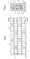
- the drywall system according to the invention is constructed from essentially rectangular building blocks 1 which have recesses in the corners on their mutually facing butt sides, so that they can also be arranged at an angle to one another.
- the drywall system is usually placed on a solid surface or concrete base, the blocks 1 being arranged offset to one another.
- approximately square modules 2 are also provided for the end regions. 2 to 8 that the modules 1 and 2 have recesses 3, which are cylindrical according to the FIG.
- these recesses can have various other cross sections and can also be conical.
- the blocks 1 and 2 arranged within the dry stone wall have continuous recesses, whereas, according to FIG. 2, the upper layer has recesses which only partially extend into the blocks 1 and 2, so that cover stones result.
- all of the building blocks 1 and 2 can also have continuous recesses 3, plug-shaped end pieces 4 then being provided in the upper stones.
- the building blocks 1 and 2 are connected to one another by means of peg bodies 5 which engage at least in two building blocks arranged one above the other.
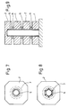
- the pin body 5 are preferably tubular and chamfered at the ends.
- Bundles 6 are provided between components 1 and 2 arranged one above the other, which are produced in one piece with the pin body 5 according to FIGS. 2, 3 and 5. 4, 6 and 9, the collars 6 are made as individual pieces and arranged on the outer circumference of the pin body 5.
- the pin body 5 according to FIG. 3 also has recesses 9 in its sleeve-shaped area, which merge into cavities 10 in the collar 6.
- these cavities and recesses can penetrate them with concrete, so that there is reliable support even in the event of aging or other yielding of the bundles.
- the walls between cavities and building blocks are made as thin as possible.
- Fig. 10 which shows a section through a pin body with recesses, the configurations of the recesses and cavities can be clearly seen.
- the pin bodies have webs 7 on their outer lateral surface, which are arranged circumferentially in FIGS. 5 and 7 and longitudinally in FIGS. 6 and 8. These webs 7 can, as esp 5 can be seen inclined so that they can be easily inserted into the blocks 1 and 2.
- the peg bodies can also have approximately the height of the dry stone wall and be passed through a plurality of recesses of blocks 1 and 2 arranged one above the other and possibly engage in the foundation, so that, depending on the height of the wall and the circumstances, no further fastening is required.
- the pin body 5 can also be filled with concrete in both long and short versions and possibly reinforced with iron.
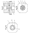
- a pin body 5 is shown similar to that of FIGS. 6 and 8, in which the radial extension of the webs 7 is made larger by reducing the sleeve.
- concrete filled into the recesses 3 can reach the area of the webs 7 and continue to the inner wall of the collar 6, the inside diameter of which is enlarged and guided over elongated webs. This can form a concrete ring that can support the building blocks independently of the collar.
- a support ring 12 is provided between the building blocks 1, the inner diameter of which is larger than the diameter of the recesses in the building blocks 1, which are denoted by 3.
- plate-shaped centering bodies 13 are fastened, which are T-shaped and fastened to the support ring with their web.
- L-shaped centering bodies can also be provided, the free legs of which then alternately engage in recesses in the lower and the module arranged above them.
- the special design of the support ring with centering bodies creates a channel along the recesses in the building blocks and the support rings, depending on the height of the wall, which can be filled with concrete, whereby due to the flat design of the centering bodies there is practically no obstruction of the concrete flow.
- the special design of the end faces of the support rings 12 according to FIGS. 17 to 19 ensures that the support rings form a tight connection with the contact surfaces of the building blocks.
- the end face can be chamfered according to FIG. 17 or equipped with a groove 14 according to FIG. 18 or a cutting edge 15 according to FIG. 16, which are flexible to the extent that unevenness in the surface of the building blocks and possibly their porosity compensates becomes.
- a support ring 16 can be arranged outside the support ring 12, which is preferably L-shaped according to FIG. 15. However, it can also be T-shaped or U-shaped. It is important that the support ring is centered on the webs or legs on the support ring 12 and, in order to support its carrying function, is at a distance from the support ring, so that it can exert a high support torque, thereby ensuring a stable alignment of the wall and a firm one Stand is guaranteed, namely even without filling the channel with concrete or the like.
- This support ring is therefore advantageously designed as an additional part and can alternatively be used.
Landscapes
- Engineering & Computer Science (AREA)
- Architecture (AREA)
- Physics & Mathematics (AREA)
- Electromagnetism (AREA)
- Civil Engineering (AREA)
- Structural Engineering (AREA)
- Revetment (AREA)
- Finishing Walls (AREA)
- Fencing (AREA)
- Building Environments (AREA)
- Joining Of Building Structures In Genera (AREA)
Priority Applications (1)
| Application Number | Priority Date | Filing Date | Title |
|---|---|---|---|
| AT85107610T ATE34419T1 (de) | 1984-07-31 | 1985-06-20 | Trockenmauer-system. |
Applications Claiming Priority (4)
| Application Number | Priority Date | Filing Date | Title |
|---|---|---|---|
| DE19843428148 DE3428148A1 (de) | 1984-07-31 | 1984-07-31 | Trockenmauer-system |
| DE3428148 | 1984-07-31 | ||
| DE19843447931 DE3447931A1 (de) | 1984-07-31 | 1984-12-15 | Trockenmauer-system |
| DE3447931 | 1984-12-15 |
Publications (2)
| Publication Number | Publication Date |
|---|---|
| EP0170840A1 true EP0170840A1 (fr) | 1986-02-12 |
| EP0170840B1 EP0170840B1 (fr) | 1988-05-18 |
Family
ID=25823435
Family Applications (1)
| Application Number | Title | Priority Date | Filing Date |
|---|---|---|---|
| EP85107610A Expired EP0170840B1 (fr) | 1984-07-31 | 1985-06-20 | Système de construction d'un mur à sec |
Country Status (5)
| Country | Link |
|---|---|
| EP (1) | EP0170840B1 (fr) |
| CA (1) | CA1258592A (fr) |
| DE (2) | DE3447931A1 (fr) |
| DK (1) | DK162300C (fr) |
| NO (1) | NO853018L (fr) |
Cited By (10)
| Publication number | Priority date | Publication date | Assignee | Title |
|---|---|---|---|---|
| GB2215749A (en) * | 1988-03-11 | 1989-09-27 | John Heelan | Apertured building blocks with locating pegs |
| EP0346558A1 (fr) * | 1988-06-14 | 1989-12-20 | Rolf Scheiwiller | Espaceur pour construction de murs en blocs superposés |
| EP0392861A1 (fr) * | 1989-04-13 | 1990-10-17 | Robert Koerner | Procédé et moyens pour construire un mur de briques |
| FR2668519A1 (fr) * | 1990-10-29 | 1992-04-30 | Millescamps Jacky | Bloc de construction pour maisons individuelles. |
| WO2001081692A1 (fr) * | 2000-04-27 | 2001-11-01 | Woodblocx Limited | Construction de blocs |
| DE19805252B4 (de) * | 1998-02-10 | 2004-03-25 | Langenstein & Schemann Gmbh | Mauertafel mit Querbalkenlagen und Trageinrichtung und Verfahren zu deren Herstellung |
| WO2006111106A3 (fr) * | 2005-04-21 | 2006-12-21 | Barquero Yap Luis Andres | Ingenierie constructive soloarmar |
| GB2443414B (en) * | 2006-11-02 | 2011-08-24 | Stuart Edward Allbrighton | A building block |
| WO2015132422A1 (fr) * | 2014-03-06 | 2015-09-11 | Industrias Audiolis, S.L. | Plaque de construction, système de construction antisismique et procédé de construction |
| ES2545162R1 (es) * | 2014-03-06 | 2015-12-10 | Industrias Audiolis, S.L. | Placa constructiva, sistema constructivo antisísmico y metodo de construccion |
Families Citing this family (3)
| Publication number | Priority date | Publication date | Assignee | Title |
|---|---|---|---|---|
| DE19633707C2 (de) * | 1996-08-21 | 2001-02-15 | Paul Kramer | Trockenmauer-System |
| DE19840774A1 (de) * | 1998-09-07 | 2000-03-09 | Bernd Beck | Verbindungsvorrichtung für Hohlblocksteine |
| ES2390685B1 (es) * | 2011-04-18 | 2013-09-30 | Joel CLAVERIAS VELASCO | Sistema constructivo. |
Citations (4)
| Publication number | Priority date | Publication date | Assignee | Title |
|---|---|---|---|---|
| DE2518739A1 (de) * | 1975-04-26 | 1976-11-04 | Schleich Josef | Verfahren, bauweise und bauelementensatz zur herstellung von waenden aus hohlkammersteinen |
| DE2650292A1 (de) * | 1975-11-17 | 1977-05-26 | Rolf Scheiwiller | Bausatz fuer trockenbauweise |
| EP0052082A1 (fr) * | 1980-11-10 | 1982-05-19 | KEYBRICK SYSTEM S.r.l. | Système pour une construction de bâtiment |
| GB2089863A (en) * | 1980-12-18 | 1982-06-30 | Moss Peter | Building Structure |
-
1984
- 1984-12-15 DE DE19843447931 patent/DE3447931A1/de not_active Ceased
-
1985
- 1985-06-20 DE DE8585107610T patent/DE3562788D1/de not_active Expired
- 1985-06-20 EP EP85107610A patent/EP0170840B1/fr not_active Expired
- 1985-07-24 CA CA000487362A patent/CA1258592A/fr not_active Expired
- 1985-07-30 DK DK346285A patent/DK162300C/da not_active IP Right Cessation
- 1985-07-30 NO NO853018A patent/NO853018L/no unknown
Patent Citations (4)
| Publication number | Priority date | Publication date | Assignee | Title |
|---|---|---|---|---|
| DE2518739A1 (de) * | 1975-04-26 | 1976-11-04 | Schleich Josef | Verfahren, bauweise und bauelementensatz zur herstellung von waenden aus hohlkammersteinen |
| DE2650292A1 (de) * | 1975-11-17 | 1977-05-26 | Rolf Scheiwiller | Bausatz fuer trockenbauweise |
| EP0052082A1 (fr) * | 1980-11-10 | 1982-05-19 | KEYBRICK SYSTEM S.r.l. | Système pour une construction de bâtiment |
| GB2089863A (en) * | 1980-12-18 | 1982-06-30 | Moss Peter | Building Structure |
Cited By (11)
| Publication number | Priority date | Publication date | Assignee | Title |
|---|---|---|---|---|
| GB2215749A (en) * | 1988-03-11 | 1989-09-27 | John Heelan | Apertured building blocks with locating pegs |
| EP0346558A1 (fr) * | 1988-06-14 | 1989-12-20 | Rolf Scheiwiller | Espaceur pour construction de murs en blocs superposés |
| US4965978A (en) * | 1988-06-14 | 1990-10-30 | Rolf Scheiwiller | Spacers for the construction of walls from superimposed blocks |
| EP0392861A1 (fr) * | 1989-04-13 | 1990-10-17 | Robert Koerner | Procédé et moyens pour construire un mur de briques |
| FR2668519A1 (fr) * | 1990-10-29 | 1992-04-30 | Millescamps Jacky | Bloc de construction pour maisons individuelles. |
| DE19805252B4 (de) * | 1998-02-10 | 2004-03-25 | Langenstein & Schemann Gmbh | Mauertafel mit Querbalkenlagen und Trageinrichtung und Verfahren zu deren Herstellung |
| WO2001081692A1 (fr) * | 2000-04-27 | 2001-11-01 | Woodblocx Limited | Construction de blocs |
| WO2006111106A3 (fr) * | 2005-04-21 | 2006-12-21 | Barquero Yap Luis Andres | Ingenierie constructive soloarmar |
| GB2443414B (en) * | 2006-11-02 | 2011-08-24 | Stuart Edward Allbrighton | A building block |
| WO2015132422A1 (fr) * | 2014-03-06 | 2015-09-11 | Industrias Audiolis, S.L. | Plaque de construction, système de construction antisismique et procédé de construction |
| ES2545162R1 (es) * | 2014-03-06 | 2015-12-10 | Industrias Audiolis, S.L. | Placa constructiva, sistema constructivo antisísmico y metodo de construccion |
Also Published As
| Publication number | Publication date |
|---|---|
| DK346285D0 (da) | 1985-07-30 |
| EP0170840B1 (fr) | 1988-05-18 |
| NO853018L (no) | 1986-02-03 |
| DK162300B (da) | 1991-10-07 |
| DE3447931A1 (de) | 1986-06-26 |
| DK346285A (da) | 1986-02-01 |
| DK162300C (da) | 1992-03-16 |
| CA1258592A (fr) | 1989-08-22 |
| DE3562788D1 (en) | 1988-06-23 |
Similar Documents
| Publication | Publication Date | Title |
|---|---|---|
| DE2443329C3 (de) | Formstein aus Beton für eine Stützmauer | |
| EP0170840B1 (fr) | Système de construction d'un mur à sec | |
| DE2903844A1 (de) | Verbindbare bauelemente | |
| DE19754922A1 (de) | Bausteine aus Beton | |
| DE3429097A1 (de) | Baustein fuer gemauerte konstruktionen sowie aus solchen bausteinen gebildete mauer | |
| DE2650292C3 (de) | Bausteinsatz | |
| EP0671508A2 (fr) | Pavé | |
| AT394222B (de) | Formstein, vorzugsweise aus beton | |
| EP0644302A2 (fr) | Jeu de blocs de construction | |
| DE3428148A1 (de) | Trockenmauer-system | |
| DE3311015C2 (fr) | ||
| DE2104105C3 (de) | Keramischer Stein | |
| DE2361029A1 (de) | Schalungsstein | |
| DE2921113A1 (de) | Schalungsstein | |
| DE2926621A1 (de) | Bauelement zur herstellung prismatischer wandkonstruktionen | |
| DE19633707A1 (de) | Trockenmauer-System | |
| CH671990A5 (fr) | ||
| DE2626407A1 (de) | Biegesteife steckverbindung zum verbinden von regal-, geruest-, tribuenen-, treppen- oder dergleichen bauteilen | |
| DE838811C (de) | Hohlwand | |
| DE3704444A1 (de) | Verfahren zum hochziehen von mauern und bausatz zum durchfuehren des verfahrens | |
| DE866382C (de) | Baustein und Bausteinanordnung | |
| DE3442183A1 (de) | Plattensystem mit wenigstens einer platte aus zementgebundenem material | |
| DE202015104127U1 (de) | Modulares Wandelement | |
| DE2639036A1 (de) | Mauerstein | |
| WO2021259946A1 (fr) | Élément de liaison pour corps de revêtement de plancher, et entretoise transversale |
Legal Events
| Date | Code | Title | Description |
|---|---|---|---|
| PUAI | Public reference made under article 153(3) epc to a published international application that has entered the european phase |
Free format text: ORIGINAL CODE: 0009012 |
|
| AK | Designated contracting states |
Kind code of ref document: A1 Designated state(s): AT BE CH DE FR GB IT LI LU NL SE |
|
| 17P | Request for examination filed |
Effective date: 19860219 |
|
| 17Q | First examination report despatched |
Effective date: 19870217 |
|
| GRAA | (expected) grant |
Free format text: ORIGINAL CODE: 0009210 |
|
| AK | Designated contracting states |
Kind code of ref document: B1 Designated state(s): AT BE CH DE FR GB IT LI LU NL SE |
|
| PG25 | Lapsed in a contracting state [announced via postgrant information from national office to epo] |
Ref country code: IT Free format text: LAPSE BECAUSE OF FAILURE TO SUBMIT A TRANSLATION OF THE DESCRIPTION OR TO PAY THE FEE WITHIN THE PRESCRIBED TIME-LIMIT;WARNING: LAPSES OF ITALIAN PATENTS WITH EFFECTIVE DATE BEFORE 2007 MAY HAVE OCCURRED AT ANY TIME BEFORE 2007. THE CORRECT EFFECTIVE DATE MAY BE DIFFERENT FROM THE ONE RECORDED. Effective date: 19880518 |
|
| REF | Corresponds to: |
Ref document number: 34419 Country of ref document: AT Date of ref document: 19880615 Kind code of ref document: T |
|
| PG25 | Lapsed in a contracting state [announced via postgrant information from national office to epo] |
Ref country code: SE Effective date: 19880531 |
|
| REF | Corresponds to: |
Ref document number: 3562788 Country of ref document: DE Date of ref document: 19880623 |
|
| ET | Fr: translation filed | ||
| GBV | Gb: ep patent (uk) treated as always having been void in accordance with gb section 77(7)/1977 [no translation filed] | ||
| PG25 | Lapsed in a contracting state [announced via postgrant information from national office to epo] |
Ref country code: GB Free format text: LAPSE BECAUSE OF NON-PAYMENT OF DUE FEES Effective date: 19881124 |
|
| PLBE | No opposition filed within time limit |
Free format text: ORIGINAL CODE: 0009261 |
|
| STAA | Information on the status of an ep patent application or granted ep patent |
Free format text: STATUS: NO OPPOSITION FILED WITHIN TIME LIMIT |
|
| 26N | No opposition filed | ||
| PGFP | Annual fee paid to national office [announced via postgrant information from national office to epo] |
Ref country code: AT Payment date: 19930519 Year of fee payment: 9 |
|
| PGFP | Annual fee paid to national office [announced via postgrant information from national office to epo] |
Ref country code: BE Payment date: 19930601 Year of fee payment: 9 |
|
| PGFP | Annual fee paid to national office [announced via postgrant information from national office to epo] |
Ref country code: LU Payment date: 19930609 Year of fee payment: 9 |
|
| PGFP | Annual fee paid to national office [announced via postgrant information from national office to epo] |
Ref country code: FR Payment date: 19930628 Year of fee payment: 9 |
|
| PGFP | Annual fee paid to national office [announced via postgrant information from national office to epo] |
Ref country code: NL Payment date: 19930630 Year of fee payment: 9 |
|
| EPTA | Lu: last paid annual fee | ||
| PGFP | Annual fee paid to national office [announced via postgrant information from national office to epo] |
Ref country code: CH Payment date: 19930923 Year of fee payment: 9 |
|
| PG25 | Lapsed in a contracting state [announced via postgrant information from national office to epo] |
Ref country code: LU Free format text: LAPSE BECAUSE OF NON-PAYMENT OF DUE FEES Effective date: 19940620 Ref country code: AT Effective date: 19940620 |
|
| PG25 | Lapsed in a contracting state [announced via postgrant information from national office to epo] |
Ref country code: LI Effective date: 19940630 Ref country code: CH Effective date: 19940630 Ref country code: BE Effective date: 19940630 |
|
| BERE | Be: lapsed |
Owner name: METTEN PRODUKTIONS- UND HANDELS G.M.B.H. Effective date: 19940630 |
|
| PG25 | Lapsed in a contracting state [announced via postgrant information from national office to epo] |
Ref country code: NL Effective date: 19950101 |
|
| NLV4 | Nl: lapsed or anulled due to non-payment of the annual fee | ||
| PG25 | Lapsed in a contracting state [announced via postgrant information from national office to epo] |
Ref country code: FR Effective date: 19950228 |
|
| REG | Reference to a national code |
Ref country code: CH Ref legal event code: PL |
|
| REG | Reference to a national code |
Ref country code: FR Ref legal event code: ST |
|
| PGFP | Annual fee paid to national office [announced via postgrant information from national office to epo] |
Ref country code: DE Payment date: 19960801 Year of fee payment: 12 |
|
| PG25 | Lapsed in a contracting state [announced via postgrant information from national office to epo] |
Ref country code: DE Free format text: LAPSE BECAUSE OF NON-PAYMENT OF DUE FEES Effective date: 19980303 |