EP0172049A1 - Ergonomischer Arbeitstisch mit senkrecht bewegbaren Platten - Google Patents
Ergonomischer Arbeitstisch mit senkrecht bewegbaren Platten Download PDFInfo
- Publication number
- EP0172049A1 EP0172049A1 EP85401253A EP85401253A EP0172049A1 EP 0172049 A1 EP0172049 A1 EP 0172049A1 EP 85401253 A EP85401253 A EP 85401253A EP 85401253 A EP85401253 A EP 85401253A EP 0172049 A1 EP0172049 A1 EP 0172049A1
- Authority
- EP
- European Patent Office
- Prior art keywords
- console
- vertically movable
- work
- box
- plates
- Prior art date
- Legal status (The legal status is an assumption and is not a legal conclusion. Google has not performed a legal analysis and makes no representation as to the accuracy of the status listed.)
- Granted
Links
- 238000003466 welding Methods 0.000 claims abstract description 7
- 238000003860 storage Methods 0.000 claims abstract description 5
- 230000007246 mechanism Effects 0.000 claims description 8
- 238000005516 engineering process Methods 0.000 claims description 2
- 230000001105 regulatory effect Effects 0.000 claims description 2
- 238000009434 installation Methods 0.000 abstract description 3
- 238000004873 anchoring Methods 0.000 description 3
- 238000006073 displacement reaction Methods 0.000 description 3
- 238000004519 manufacturing process Methods 0.000 description 3
- 238000010586 diagram Methods 0.000 description 2
- 210000002414 leg Anatomy 0.000 description 2
- 238000000034 method Methods 0.000 description 2
- 230000008569 process Effects 0.000 description 2
- 241000135309 Processus Species 0.000 description 1
- 240000008042 Zea mays Species 0.000 description 1
- 230000004308 accommodation Effects 0.000 description 1
- 230000009471 action Effects 0.000 description 1
- 230000000712 assembly Effects 0.000 description 1
- 238000000429 assembly Methods 0.000 description 1
- 230000001276 controlling effect Effects 0.000 description 1
- 230000008878 coupling Effects 0.000 description 1
- 238000010168 coupling process Methods 0.000 description 1
- 238000005859 coupling reaction Methods 0.000 description 1
- 238000010616 electrical installation Methods 0.000 description 1
- 230000006872 improvement Effects 0.000 description 1
- 210000003127 knee Anatomy 0.000 description 1
- 230000009467 reduction Effects 0.000 description 1
- 230000000630 rising effect Effects 0.000 description 1
- 238000005476 soldering Methods 0.000 description 1
Images



Classifications
-
- B—PERFORMING OPERATIONS; TRANSPORTING
- B25—HAND TOOLS; PORTABLE POWER-DRIVEN TOOLS; MANIPULATORS
- B25H—WORKSHOP EQUIPMENT, e.g. FOR MARKING-OUT WORK; STORAGE MEANS FOR WORKSHOPS
- B25H1/00—Work benches; Portable stands or supports for positioning portable tools or work to be operated on thereby
- B25H1/14—Work benches; Portable stands or supports for positioning portable tools or work to be operated on thereby with provision for adjusting the bench top
- B25H1/16—Work benches; Portable stands or supports for positioning portable tools or work to be operated on thereby with provision for adjusting the bench top in height
-
- H—ELECTRICITY
- H05—ELECTRIC TECHNIQUES NOT OTHERWISE PROVIDED FOR
- H05K—PRINTED CIRCUITS; CASINGS OR CONSTRUCTIONAL DETAILS OF ELECTRIC APPARATUS; MANUFACTURE OF ASSEMBLAGES OF ELECTRICAL COMPONENTS
- H05K13/00—Apparatus or processes specially adapted for manufacturing or adjusting assemblages of electric components
- H05K13/0053—Arrangements for assisting the manual mounting of components, e.g. special tables or light spots indicating the place for mounting
Definitions
- the present invention relates to work tables of limited surface placed at the disposal of an operator with a view to carrying out a series of determined operations therein and it relates more particularly to the filling of printed circuit boards with electronic components before their fixing. definitive.
- the printed circuits receive in holes provided for this purpose, the tails of the electronic components which protrude at the emergence of the opposite face to be soldered there which ensures both their electrical connection on the printed conductive tracks and their final material fixation. .
- equipment comprising an ergonomic work table with a fixed station where the work surface, with a limited surface, is retracted vertically in a receptacle according to a rigorously vertical movement process and without coupling or jerking. .
- the operator can work comfortably without fatigue on each tray in the work plan and then and as soon as his work is completed on a tray, translate said tray using appropriate mechanisms, in the upper receptacle and , by a movement without lull or any shaking.
- the invention will therefore propose a work table in the form of a console presenting the required ergonomic criteria and which makes it possible, on the one hand, to treat, by the appreciable surface of each work plate, a relatively high quantity of elementary units and On the other hand, due to the increase in the number of plates that can be accommodated in the fairings, a higher number of elements in a single manufacturing cycle.
- the invention is useful for the disabled who can accommodate their wheelchair under the console and who no longer have tedious lateral movements to perform.
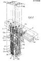
- the console forming the work table essentially comprises a rigid structure marked 1 as a whole and which comprises: a stable rigid seat 2, a box 3 a work box 4 and a upper receptacle 5
- the seat may also include ground anchoring points 6 or setting screws.
- the working box 4 is hollowed out at 7 to allow the setting up of the work trays 8-9-10- and 11 which it is used discussed below.
- the tray being fitted (Ref. 8 on the drawing) is flush with the worktop of the box 4 so that the assembly constitutes a continuous worktop whose height of about 0.85 m has been chosen in according to the ergonomic criteria in use. Similarly the clearance of the lower part was determined to ensure easy passage of the legs.
- the rigidity of the assembly has also been provided so that the box and the tray can support a payload of at least 100 kg.
- the working operating field has also been provided so that the operator can access the entire surface of a tray without moving her seat, just as her comfort is supplemented by a footrest support bar 12.
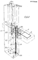
- Figure 2 shows the various mechanisms required to secure the trays and move them vertically upwards.
- FIG. 2 represents in fact the systems for the plates 10 and 11 for reasons of clarity in reading the drawing.
- the last plate 11 is placed horizontally on a bracket 18 and then fixed by the Device 17.
- the bracket 18 receives, in its vertical part downwards and at its four corners, ball bearings 19a, 19b 20a and? Ob sliding on rectilinear cylindrical bars 21, 22 rigidly fixed to the box 3 by anchoring supports 23a, 23b, and 24a, 24b (not shown in full).
- passage holes 25al, 25a2 and? 5b1, 25b2 ensure the passage of the other bars.
- the console box 4 is broken on each side at 4a in order to allow the passage of all the brackets.
- the penultimate tray 10 is similarly positioned on a bracket 26 and the four ball bearings 27a,? 7b and 28a, 28b are also arranged at the four corners of the rising part of said console and on the same bars 21 , 22 as for the plate 11 previously described.
- holes 29al, 29a2, and 29bl, 29b2 ensure the passage of the other bars.
- brackets can move with precision and smoothness during their movement of movement of the plates either up or down.
- the sliding assemblies are completed by a displacement control assembly by jacks 30, 31 taking support; on the one hand on legs 32, 33 secured to the brackets and on the other hand, on the bottom of the box 3.
- FIG. 4 also shows a still similar operation of the first plate 8 where there is encountered for this purpose a bracket 46 with its plate positioning devices 17, ball bearings 47a, 47b and 48a, 48b, bars guide 49, 50 and anchoring supports 51a, 51b, and 52a, 52b (these bars and supports not being shown in the drawing)
- the equipment is completed by the jack 53 (with its control motor 54) bearing on the lug 53 secured to the bracket 46 and on the bottom of the box 3.
- the electrical circuit according to the diagram in FIG. 5 essentially comprises; the four actuator motors 34, 35, 44, 54 supplied from a control center using the so-called "MOS" technology and identified 56 whose regulated power supply 57 is supplied by the sector through a transformer 58.
- a series of limit switches 59, 60, 61, 62 ensure the inversion of the motors at the end of the chainrings travel when the latter are raised or lowered.
- overload detectors for safety 63, 64, 65, 66 cut off the supply to said motors if an anomaly occurs.
- indicator lights indicate the operations in progress according to use.
- the keys 13, 14, 15, 16 made available to the operator ensure the movements of raising or lowering of the platforms
- the work console with vertical displacement of tables housed either in a work box with an ergonomic conformation or in an upper receptacle indeed provides the characteristics proposed by the invention and which aim, on the one hand, a reduction in the horizontal occupation surface of the printed circuits as encountered in the prior art and on the other hand, an improvement in the comfort of the operators who find in their field of action an accessible working surface without displacement.
Landscapes
- Engineering & Computer Science (AREA)
- Manufacturing & Machinery (AREA)
- Microelectronics & Electronic Packaging (AREA)
- Mechanical Engineering (AREA)
- Vehicle Step Arrangements And Article Storage (AREA)
- Supply And Installment Of Electrical Components (AREA)
- Workshop Equipment, Work Benches, Supports, Or Storage Means (AREA)
- Mattresses And Other Support Structures For Chairs And Beds (AREA)
- Electric Connection Of Electric Components To Printed Circuits (AREA)
Priority Applications (1)
| Application Number | Priority Date | Filing Date | Title |
|---|---|---|---|
| AT85401253T ATE72916T1 (de) | 1984-07-13 | 1985-06-24 | Ergonomischer arbeitstisch mit senkrecht bewegbaren platten. |
Applications Claiming Priority (2)
| Application Number | Priority Date | Filing Date | Title |
|---|---|---|---|
| FR8411166 | 1984-07-13 | ||
| FR8411166A FR2567377B1 (fr) | 1984-07-13 | 1984-07-13 | Console de travail ergonomique a plateaux mobiles verticalement. |
Publications (2)
| Publication Number | Publication Date |
|---|---|
| EP0172049A1 true EP0172049A1 (de) | 1986-02-19 |
| EP0172049B1 EP0172049B1 (de) | 1992-02-26 |
Family
ID=9306107
Family Applications (1)
| Application Number | Title | Priority Date | Filing Date |
|---|---|---|---|
| EP19850401253 Expired - Lifetime EP0172049B1 (de) | 1984-07-13 | 1985-06-24 | Ergonomischer Arbeitstisch mit senkrecht bewegbaren Platten |
Country Status (4)
| Country | Link |
|---|---|
| EP (1) | EP0172049B1 (de) |
| AT (1) | ATE72916T1 (de) |
| DE (1) | DE3585420D1 (de) |
| FR (1) | FR2567377B1 (de) |
Cited By (5)
| Publication number | Priority date | Publication date | Assignee | Title |
|---|---|---|---|---|
| EP0178225A3 (en) * | 1984-10-09 | 1987-05-27 | Toniazzo Josephine | Magnetic rods positioning system |
| GB2219547A (en) * | 1988-06-03 | 1989-12-13 | Samuel Thomas | Work bench |
| WO1990013398A1 (en) * | 1989-05-11 | 1990-11-15 | Sibola A/S | Working table |
| FR2664787A1 (fr) * | 1990-07-12 | 1992-01-17 | Toniaazzo Josephine | Console a plateaux defilant horizontalement. |
| FR3002473A1 (fr) * | 2013-02-22 | 2014-08-29 | Peugeot Citroen Automobiles Sa | Pupitre de travail ergonomique et procede pour le chargement et le dechargement d'une piece sur le pupitre |
Citations (2)
| Publication number | Priority date | Publication date | Assignee | Title |
|---|---|---|---|---|
| US3426415A (en) * | 1966-09-26 | 1969-02-11 | Mohawk Data Sciences Corp | Printed circuit assembly apparatus |
| DE2751856A1 (de) * | 1977-11-21 | 1979-05-23 | Fritz Hans Ulrich Dipl Ing | Bestueckungsanordnung |
-
1984
- 1984-07-13 FR FR8411166A patent/FR2567377B1/fr not_active Expired
-
1985
- 1985-06-24 DE DE8585401253T patent/DE3585420D1/de not_active Expired - Lifetime
- 1985-06-24 AT AT85401253T patent/ATE72916T1/de not_active IP Right Cessation
- 1985-06-24 EP EP19850401253 patent/EP0172049B1/de not_active Expired - Lifetime
Patent Citations (2)
| Publication number | Priority date | Publication date | Assignee | Title |
|---|---|---|---|---|
| US3426415A (en) * | 1966-09-26 | 1969-02-11 | Mohawk Data Sciences Corp | Printed circuit assembly apparatus |
| DE2751856A1 (de) * | 1977-11-21 | 1979-05-23 | Fritz Hans Ulrich Dipl Ing | Bestueckungsanordnung |
Cited By (5)
| Publication number | Priority date | Publication date | Assignee | Title |
|---|---|---|---|---|
| EP0178225A3 (en) * | 1984-10-09 | 1987-05-27 | Toniazzo Josephine | Magnetic rods positioning system |
| GB2219547A (en) * | 1988-06-03 | 1989-12-13 | Samuel Thomas | Work bench |
| WO1990013398A1 (en) * | 1989-05-11 | 1990-11-15 | Sibola A/S | Working table |
| FR2664787A1 (fr) * | 1990-07-12 | 1992-01-17 | Toniaazzo Josephine | Console a plateaux defilant horizontalement. |
| FR3002473A1 (fr) * | 2013-02-22 | 2014-08-29 | Peugeot Citroen Automobiles Sa | Pupitre de travail ergonomique et procede pour le chargement et le dechargement d'une piece sur le pupitre |
Also Published As
| Publication number | Publication date |
|---|---|
| FR2567377A1 (fr) | 1986-01-17 |
| ATE72916T1 (de) | 1992-03-15 |
| FR2567377B1 (fr) | 1986-11-14 |
| EP0172049B1 (de) | 1992-02-26 |
| DE3585420D1 (de) | 1992-04-02 |
Similar Documents
| Publication | Publication Date | Title |
|---|---|---|
| EP0343077B1 (de) | Autonomer Modul für die Intensivpflege und Reanimation | |
| FR2585276A2 (fr) | Machine executant diverses operations d'usinage telles que tournage, fraisage, alesage | |
| EP0593367B1 (de) | System zum Transportieren und Speichern von flachen Gegenständen wie extra-flachen Dosen und tragbares Lagergestell dafür | |
| EP0172049B1 (de) | Ergonomischer Arbeitstisch mit senkrecht bewegbaren Platten | |
| CH649021A5 (fr) | Machine a usiner par decharges electriques erosives. | |
| FR2609797A1 (fr) | Niveau a faisceau laser | |
| FR2553071A1 (fr) | Appareil et procede pour la manipulation d'articles | |
| FR2648857A1 (fr) | Installation pour l'assemblage automatique de la douille-equerre d'ouvrants | |
| FR2743741A1 (fr) | Structure logique d'une machine-outil d'usinage a grande vitesse du type porte-broche | |
| WO1987000493A1 (fr) | Installation modulaire pour le transport controle de pieces ou de produits | |
| FR2644568A1 (fr) | Dispositif d'intervention, notamment pour le controle, l'inspection et la maintenance des echangeurs de chaleur | |
| FR2597023A1 (fr) | Dispositif de manutention pour echanger les outils d'une presse a decouper | |
| FR2491048A1 (fr) | Installation de levage d'une charge de grande dimension a l'aide de plusieurs dispositifs de levage independants agissant en plusieurs points de charge, notamment destinee au levage d'un avion en vue de sa reparation | |
| EP0876238B1 (de) | Montagezelle mit anpassbarer konfigurationsfunktion | |
| CH682914A5 (fr) | Dispositif de levage et de déplacement de charges. | |
| FR2956800A1 (fr) | Siege de piano motorise | |
| JP2010216139A (ja) | 床用目地装置 | |
| EP0572716B1 (de) | Elektroerosive Maschine mit einem befestigten Werkstück | |
| WO2019162634A1 (fr) | Dispositif de fabrication additive | |
| EP1441620A1 (de) | Variabler arbeitsplatz | |
| EP0165130A1 (de) | Büromöbel | |
| FR2723661A1 (fr) | Installation pour la mise en place d'assemblages de combustible nucleaire | |
| FR2826897A1 (fr) | Mecanisme de chargement et de dechargement de boites renfermant des plaquettes de microelectronique pour le transfert de l'equipement a un chariot de transport, et inversement | |
| FR2594370A1 (fr) | Machine transfert pour l'assemblage des pieces d'ensembles divers | |
| CA3021750C (fr) | Manipulateur de piece |
Legal Events
| Date | Code | Title | Description |
|---|---|---|---|
| PUAI | Public reference made under article 153(3) epc to a published international application that has entered the european phase |
Free format text: ORIGINAL CODE: 0009012 |
|
| AK | Designated contracting states |
Designated state(s): AT BE CH DE FR GB IT LI LU NL SE |
|
| 17P | Request for examination filed |
Effective date: 19860319 |
|
| 17Q | First examination report despatched |
Effective date: 19870529 |
|
| GRAA | (expected) grant |
Free format text: ORIGINAL CODE: 0009210 |
|
| AK | Designated contracting states |
Kind code of ref document: B1 Designated state(s): AT BE CH DE FR GB IT LI LU NL SE |
|
| PG25 | Lapsed in a contracting state [announced via postgrant information from national office to epo] |
Ref country code: GB Effective date: 19920226 Ref country code: SE Effective date: 19920226 Ref country code: AT Effective date: 19920226 Ref country code: NL Effective date: 19920226 Ref country code: IT Free format text: LAPSE BECAUSE OF FAILURE TO SUBMIT A TRANSLATION OF THE DESCRIPTION OR TO PAY THE FEE WITHIN THE PRESCRIBED TIME-LIMIT;WARNING: LAPSES OF ITALIAN PATENTS WITH EFFECTIVE DATE BEFORE 2007 MAY HAVE OCCURRED AT ANY TIME BEFORE 2007. THE CORRECT EFFECTIVE DATE MAY BE DIFFERENT FROM THE ONE RECORDED. Effective date: 19920226 |
|
| REF | Corresponds to: |
Ref document number: 72916 Country of ref document: AT Date of ref document: 19920315 Kind code of ref document: T |
|
| REF | Corresponds to: |
Ref document number: 3585420 Country of ref document: DE Date of ref document: 19920402 |
|
| PG25 | Lapsed in a contracting state [announced via postgrant information from national office to epo] |
Ref country code: CH Effective date: 19920630 Ref country code: BE Effective date: 19920630 Ref country code: LI Effective date: 19920630 Ref country code: LU Free format text: LAPSE BECAUSE OF NON-PAYMENT OF DUE FEES Effective date: 19920630 |
|
| RAP2 | Party data changed (patent owner data changed or rights of a patent transferred) |
Owner name: CALEO SARL |
|
| RIN2 | Information on inventor provided after grant (corrected) |
Free format text: TONIAZZO EPOUSE TOKARCZYK, JOSEPHINE * REMY, JACQUES |
|
| NLV1 | Nl: lapsed or annulled due to failure to fulfill the requirements of art. 29p and 29m of the patents act | ||
| GBV | Gb: ep patent (uk) treated as always having been void in accordance with gb section 77(7)/1977 [no translation filed] | ||
| PGFP | Annual fee paid to national office [announced via postgrant information from national office to epo] |
Ref country code: DE Payment date: 19921120 Year of fee payment: 8 |
|
| PLBE | No opposition filed within time limit |
Free format text: ORIGINAL CODE: 0009261 |
|
| STAA | Information on the status of an ep patent application or granted ep patent |
Free format text: STATUS: NO OPPOSITION FILED WITHIN TIME LIMIT |
|
| BERE | Be: lapsed |
Owner name: REMY JACQUES Effective date: 19920630 Owner name: TONIAZZO EPOUSE TOKARCZYK JOSEPHINE Effective date: 19920630 |
|
| 26N | No opposition filed | ||
| REG | Reference to a national code |
Ref country code: CH Ref legal event code: PL |
|
| PG25 | Lapsed in a contracting state [announced via postgrant information from national office to epo] |
Ref country code: DE Effective date: 19940301 |
|
| PGFP | Annual fee paid to national office [announced via postgrant information from national office to epo] |
Ref country code: FR Payment date: 19970905 Year of fee payment: 13 |
|
| PG25 | Lapsed in a contracting state [announced via postgrant information from national office to epo] |
Ref country code: FR Free format text: LAPSE BECAUSE OF NON-PAYMENT OF DUE FEES Effective date: 19990226 |
|
| REG | Reference to a national code |
Ref country code: FR Ref legal event code: ST |