EP0172923A1 - Atemschutzgerät als Sauerstoffselbstretter - Google Patents
Atemschutzgerät als Sauerstoffselbstretter Download PDFInfo
- Publication number
- EP0172923A1 EP0172923A1 EP84109927A EP84109927A EP0172923A1 EP 0172923 A1 EP0172923 A1 EP 0172923A1 EP 84109927 A EP84109927 A EP 84109927A EP 84109927 A EP84109927 A EP 84109927A EP 0172923 A1 EP0172923 A1 EP 0172923A1
- Authority
- EP
- European Patent Office
- Prior art keywords
- chemical cartridge
- protection device
- breathing
- coating
- respiratory protection
- Prior art date
- Legal status (The legal status is an assumption and is not a legal conclusion. Google has not performed a legal analysis and makes no representation as to the accuracy of the status listed.)
- Granted
Links
- 230000029058 respiratory gaseous exchange Effects 0.000 title claims abstract description 56
- QVGXLLKOCUKJST-UHFFFAOYSA-N atomic oxygen Chemical compound [O] QVGXLLKOCUKJST-UHFFFAOYSA-N 0.000 title claims abstract description 6
- 229910052760 oxygen Inorganic materials 0.000 title claims abstract description 6
- 239000001301 oxygen Substances 0.000 title claims abstract description 6
- 239000000126 substance Substances 0.000 claims abstract description 60
- 230000000241 respiratory effect Effects 0.000 claims abstract description 20
- 239000011248 coating agent Substances 0.000 claims description 20
- 238000000576 coating method Methods 0.000 claims description 20
- 230000001681 protective effect Effects 0.000 claims description 4
- 239000011324 bead Substances 0.000 claims description 3
- 229920002379 silicone rubber Polymers 0.000 claims description 3
- 229920000742 Cotton Polymers 0.000 claims description 2
- 230000001154 acute effect Effects 0.000 claims description 2
- 230000035939 shock Effects 0.000 claims description 2
- 239000000463 material Substances 0.000 claims 3
- 230000015572 biosynthetic process Effects 0.000 description 2
- 239000000428 dust Substances 0.000 description 2
- 238000010276 construction Methods 0.000 description 1
- 239000011810 insulating material Substances 0.000 description 1
- 238000009413 insulation Methods 0.000 description 1
- 238000000034 method Methods 0.000 description 1
- 230000000284 resting effect Effects 0.000 description 1
- 239000013585 weight reducing agent Substances 0.000 description 1
Images


Classifications
-
- A—HUMAN NECESSITIES
- A62—LIFE-SAVING; FIRE-FIGHTING
- A62B—DEVICES, APPARATUS OR METHODS FOR LIFE-SAVING
- A62B7/00—Respiratory apparatus
- A62B7/08—Respiratory apparatus containing chemicals producing oxygen
Definitions
- the present invention relates to a breathing apparatus as an oxygen self-rescuer, in particular as an escape device, according to the preamble of claim 1.
- Respiratory protective devices of the type mentioned at the outset are accommodated in airtight lockable standby containers which are used, for example, in mine operations, are constantly carried by the miner and are worn on the body. The device is removed from the standby container for use.
- the breathing bag is arranged above the chemical cartridge, the chemical cartridge being accommodated in the lower housing part and the breathing bag with the breathing tube and mouthpiece in the housing cover.
- a relatively high-profile housing cover is required, which thus substantially determines the overall size of the standby container, so that the breathing apparatus with the standby container must be worn on the body by means of a shoulder strap.
- this device carrying method is difficult for the miner who is always carrying the device.
- the invention is therefore based on the object to provide a particularly space-saving and compact design for an oxygen self-rescuer as an escape device and to save space so that the device can be accommodated in a standby container to be worn on the belt of the device wearer.
- the advantages achieved by the invention are, in particular, that the size of the breathing apparatus is reduced and the device can be accommodated in a small standby container to be worn on the belt.
- the surface and temperature of the breathing apparatus is advantageously reduced by the complete and double sheathing of the chemical cartridge, namely by the coating and by the breathing bag.
- the invention has surprisingly shown that it is possible to arrange the chemical cartridge inside the breathing bag, although it was to be expected that the heat emitted by the chemical cartridge during operation would be an unbearable burden for the breathing bag and for the air inside the breathing bag. It was to be assumed that, as before, because of the known heat load for the breathing bag, it must be arranged separately from the chemical cartridge as the heat source.
- a breathing apparatus is shown with pendulum breathing.
- the respirator consists of an oxygen-evolving chemical cartridge 1, which is insulated and shock-absorbing cover 2 is closely enclosed, a breathing tube 3 with a mouthpiece 4, a breathing bag 5 connected to the chemical cartridge 1 and a carrying strap 6.
- the breathing apparatus is accommodated in a standby container 7 according to FIG. 4.
- a heat exchanger 12 is arranged above the inlet opening D of the chemical cartridge 1 and is designed such that no heat contact can occur between the heat exchanger 12 and the chemical cartridge 1.
- the heat exchanger 12 is surrounded by a heat-insulating housing socket 17 which rests captively on the top of the chemical cartridge 1.
- An opening 5b is provided on the upper end face 5a of the breathing bag 5, through which the chemical cartridge 1 is inserted into the breathing bag.
- the opening 5b is bordered by a web 5c, to which the chemical cartridge 1 with the cover 2 and the ends of the carrying strap 6 are fastened by means of a collar 22.
- a pressure relief valve 8 is arranged on the upper end face 5a of the breathing bag 5.
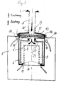
- the coating 2 shows a cross section through the chemical cartridge 1 with a coating 2.
- the coating 2 has ribs 2a, which lie at a distance from one another on the chemical cartridge outer surface A in the vertical or longitudinal axis.
- the lower end face of the chemical cartridge 1 is partially covered by the coating 2, so that the outlet opening B of the chemical cartridge is freely accessible for the exhaled and inhaled air to flow through (FIG. 1).
- the upper end face of the cartridge 1 is completely covered by the coating 2, which preferably forms a unit with the breathing tube 3.
- the coating 2 consists of a heat-insulating material, for example silicone elastomers. This coating 2 contributes to the fact that, in the operating state, the heat load due to the exothermic reaction of the oxygen-developing chemical is low for the breathing bag 5 enveloping the chemical cartridge 1.
- the formation of the coating 2 with the ribs 2a resting on the chemical cartridge outer surface A creates between the cartridge outer turn A and the coating 2 All around spaces C (see. Fig. 2), which serve as thermal insulation and lower the surface temperature of the cartridge 1.
- the formation of the cover 2 with the ribs 2a also has other advantages: the covering of the cover 2 over the chemical cartridge 1 during assembly is facilitated. Weight reduction for the cover 2, so that the weight for the device to be worn on the belt becomes smaller. The rigidity of the coating 2 is increased. Overall, the cover 2 also serves as shock protection for the breathing apparatus which is accommodated in the standby container 7.
- the air outlet surface E is advantageously loosely surrounded by cotton wool 9 holding the dust.
- the air outlet opening B of the cartridge 1 is covered by a sieve 10 protruding into the opening at an acute angle, the molten chemical into a collecting trough formed in the chemical cartridge 1 at the bottom 11 can drain without clogging the flow path.
- the breathing apparatus according to the invention is designed for circulatory breathing.
- the construction is identical to the breathing apparatus shown in FIG. 1, except for the housing 13, which houses two exhalation valves 18 and the heat exchanger 12.
- the housing 13 is connected to the inlet opening D 'of the chemical cartridge 1', by means of a pipe socket 19 which represents the inlet opening D 'and which is inserted into a pipe socket 20 connected to the housing 13.
- the pipe socket 20 is sealed against the pipe socket 19 via a seal 21.
- Inhalation takes place via the housing 13 directly from the breathing bag 5, the covering 2 being provided with slot designs 2b. This creates circulatory breathing in the device. Only the breathing tube 3 is used both for exhalation and for inhalation, i.e. H. used in pendulum breathing.
- the flow through the chemical cartridge 1 ' is indicated by the arrows.
- the standby container 7 shows the breathing apparatus in the standby container 7.
- the lower part of the standby container and 14 its lid are designated by 14. Both parts are pressed airtight against each other by known closure members (not shown).
- the standby container 7 is provided with an eyelet part 16 in order to be hung on the waist belt of the device wearer.
- the breathing apparatus must be stored in a shockproof manner in the standby container 7. This is advantageously done by beads 2c formed all around on the cover 2 at the top and bottom.
- FIG. 5 shows an enlarged illustration of the beads 2c serving as impact protection between the chemical cartridge 1 and the wall of the lower part 14 of the standby container 7.
Landscapes
- Health & Medical Sciences (AREA)
- Chemical & Material Sciences (AREA)
- Chemical Kinetics & Catalysis (AREA)
- Emergency Medicine (AREA)
- General Chemical & Material Sciences (AREA)
- Pulmonology (AREA)
- General Health & Medical Sciences (AREA)
- Business, Economics & Management (AREA)
- Emergency Management (AREA)
- Respiratory Apparatuses And Protective Means (AREA)
Abstract
Description
- Die vorliegende Erfindung betrifft ein Atemschutzgerät als Sauerstoffselbstretter, insbesondere als Fluchtgerät, nach dem Oberbegriff des Anspruchs 1.
- Atemschutzgeräte der eingangs genannten Art, sind in luftdicht verschließbaren Bereitschaftsbehältern untergebracht, die beispielsweise im Grubenbetrieb verwendet, vom Bergmann ständig mitgeführt und am Körper getragen werden. Zum Gebrauch wird das Gerät aus dem Bereitschaftsbehälter herausgenommen.
- Es liegt auf der Hand, daß ein derartiges Atemschutzgerät für ein ständiges Mitführen hinsichtlich Gewicht und Abmessungen leicht und klein sein muß.
- Bei einem bekannten Atemschutzgerät der gattungsgemäßen Art, ist der Atembeutel oberhalb der Chemikalpatrone angeordnet, wobei die Chemikalpatrone im Gehäuseunterteil und der Atembeutel mit dem Atemschlauch und Mundstück im Gehäusedeckel untergebracht sind. Dadurch ist ein verhältnismäßig hochbauender Gehäusedeckel erforderlich, der damit die Gesamtgröße des Bereitschaftsbehälters wesentlich mitbestimmt, so daß das Atemschutzgerät mit dem Bereitschaftsbehälter mittels eines Schultergurtes am Körper getragen werden muß. Bei den extrem rauhen Bedingungen im Grubenbetrieb, ist diese Gerättrageweise für den das Gerät ständig mitführenden Bergmann beschwerlich.
- Der Erfindung liegt daher die Aufgabe zugrunde, eine besonders raumsparende und kompakte Gestaltung für einen Sauerstoffselbstretter als Fluchtgerät zu schaffen und so platzsparend auszubilden, daß das Gerät in einem am Gürtel des Gerätträgers zu tragenden Bereitschaftsbehälter untergebracht werden kann.
- Diese Aufgabe wird gemäß der Erfindung bei einem Atemschutzgerät der eingangs genannten Art durch die kennzeichnenden Merkmale des Anspruchs 1 gelöst.
- Die mit der Erfindung erzielten Vorteile bestehen insbesondere darin, daß die Baugröße des Atemschutzgerätes verringert wird und dadurch das Gerät in einem am Gürtel zu tragenden kleinen Bereitschaftsbehälter untergebracht werden kann. Darüber hinaus wird durch die vollständige und doppelte Umhüllung der Chemikalpatrone, nämlich durch den Überzug und durch den Atembeutel, die Oberflächentemperatur des Atemschutzgeräges vorteilhaft vermindert.
- Die Erfindung hat in überraschender Weise gezeigt, daß es möglich ist, die Chemikalpatrone im Innern des Atembeutels anzuordnen, obwohl zu erwarten war, daß die von der Chemikalpatrone im Betrieb abgegebene Wärme für den Atembeutel und für die im Atembeutel befindliche Einetemluft eine unerträgliche Belastung darstellt, Es war davon auszugehen, daß, wie bisher, wegen der bekannten Wärmebelastung für den Atembeutel, dieser von der Chemikalpatrone als Wärmequelle unbedingt getrennt anzuordnen ist.
- Weitere vorteilhafte Ausgestaltungen der Erfindung ergeben sich aus den Unteransprüchen.
- Ausführungsbeispiele der Erfindung sind in der Zeichnung dargestellt und werden im folgenden näher beschrieben. Es zeigen:
- Fig. 1 Eine schematische Darstellung des erfindungsgemäßen Atemschutzgerätes mit Pendelatmung,
- Fig. 2 eine Schnittdarstellung nach Linie I - I, gemäß Fig. 1,
- Fig. 3 eine schematische Darstellung des erfindungsgemäßen Atemschutzgerätes mit Kreislaufatmung,
- Fig. 4 eine schematische Darstellung des in einem Bereitschaftsbehälter untergebrachten erfindungsgemäßen Atemschutzgeräts,
- Fig. 5 eine vergrößerte Detaildarstellung x nach Fig. 4
- In Fig. 1 ist ein erfindungsgemäßes Atemschutzgerät mit Pendelatmung dargestellt. Das Atemschutzgerät besteht aus einer sauerstoffentwickelnden Chemikalpatrone 1, die von einem wärmedämmenden und stoßdämpfenden Überzug 2 eng umschlossen ist, einem Atemschlauch 3 mit einem Mundstück 4, einem an die Chemikalpatrone 1 angeschlossenen Atembeutel 5 und einer Tragebänderung 6. Das Atemschutzgerät ist in einem Bereitschaftsbehälter 7 nach Fig. 4 untergebracht.
- Oberhalb der Eintrittsöffnung D der Chemikalpatrone 1 ist ein Wärmeaustauscher 12 angeordnet und so ausgebildet, daß zwischen dem Wärmeaustauscher 12 und der Chemikalpatrone 1 kein Wärmekontakt auftreten kann. Der Wärmeaustauscher 12 ist von einer wärmedämmenden Gehäuse-Fassung 17 umgeben, die auf der Oberseite der Chemikalpatrone 1 unverlierbar aufliegt.
- An der oberen Stirnseite 5a des Atembeutels 5 ist eine Öffnung 5b vorgesehen, durch die die Chemikalpatrone 1 in den Atembeutel gesteckt wird. Die Öffnung 5b ist von einem Steg 5c eingefaßt, an dem die Chemikalpatrone 1 mit dem Überzug 2 und die Enden der Tragebänderung 6 mittels einer Verschellung 22 befestigt werden. Ein Überdruckventil 8 ist an der oberen Stirnseite 5a des Atembeutels 5 angeordnet.
- In Fig. 2 ist ein Querschnitt durch die Chemikalpatrone 1 mit Überzug 2 dargestellt. Der Überzug 2 weist Rippen 2a auf, die in einem Abstand zueinander an der Chemikalpatronen-Mantelfläche A in der Hoch- bzw. Längsachse fest anliegen.
- Die untere Stirnfläche der Chemikalpatrone 1 wird vom Überzug 2 teilweise umfaßt, so daß die Austrittsöffnung B der Chemikalpatrone zum Durchströmen der Aus- und Einatemluft frei zugänglich ist (Fig. 1). Die obere Stirnfläche der Patrone 1 wird von dem Überzug 2 vollständig überdeckt, der mit dem Atemschlauch 3 vorzugsweise eine Einheit bildet.
- Der Überzug 2 besteht aus einem wärmeisolierenden Material, beispielsweise aus Silikon-Elastomere. Dieser Überzug 2 trägt mit dazu bei, daß im Betriebszustand die Wärmebelastung infolge der exothermen Reaktion des sauerstoffentwickelnden Chemikals für den die Chemikalpatrone 1 umhüllenden Atembeutel 5 gering ist. Durch die Ausbildung des Überzugs 2 mit den an der Chemikalpatronen-Mantelfläche A anliegenden Rippen 2a, entstehen zwischen der Patronen-Außenwend A und dem Überzug 2 ringsum Zwischenräume C (vgl. Fig. 2), die als Wärmeisolation dienen und die Oberflächentemperatur der Patrone 1 senken. Die Ausbildung des Überzugs 2 mit den Rippen 2a bringt darüber hinaus auch noch weitere Vorteile mit sich: Das Überziehen des Überzugs 2 über die Chemikalpatrone 1 bei der Montage wird erleichtert. Gewichtsreduzierung für den Überzug 2, so daß das Gewicht für das am Gürtel zu tragende Gerät kleiner wird. Die Steifigkeit des Überzugs 2 wird erhöht. Insgesamt dient der Überzug 2 auch als Stoßschutz für das im Bereitschaftsbehälter 7 untergebrachte Atemschutzgerät.
- Um eine optimale Ausnutzung des sauerstofferzeugenden Chemikals und damit eine größere Benutzungszeit des Atemschutzgerätes für den Gerätträger zu erzielen, muß eine über das gesamte Volumen des Chemikals gleichmäßige Durchströmung angestrebt werden. Dies wird durch eine möglichst große Anströmfläche erreicht, indem die Ausatemluft des Gerätträgers durch den Atemschlauch 3 in die Chemikalpatrone 1 durch das Chemikal im oberen Bereich axial nach unten und im seitlichen Bereich radial von außen nach innen strömt. Hierbei ragt die Luftaustrittsfläche E domartig in die Chemikalpatrone 1 hinein. Die Durchströmung der Patrone wird durch die Pfeile angegeben.
- Um zu verhindern, daß Chemikalstaub aus der Patrone 1 in den Atembeutel 5 gelangt, wird die Luftaustrittsfläche E vorteilhaft v-on einer den Staub haltenden Watte 9 lose umgeben. Um zu verhindern, daß geschmolzenes Chemikal evtl. aus der Patrone 1 in den Atembeutel 5 hineinlaufen kann, ist die Luftaustrittsöffnung B der Patrone 1 von einem spitzwinklig in die Öffnung hineinragenden Sieb 10 abgedeckt, das geschmolzenes Chemikal in eine in der Chemikalpatrone 1 unten ausgebildete Auffangwanne 11 ableiten kann, ohne den Strömungsweg zu verstopfen.
- In Fig. 3 ist das erfindungsgemäße Atemschutzgerät für Kreislaufatmung ausgebildet. Der Aufbau ist mit dem in Fig. 1 dargestellten Atemschutzgerät identisch, bis auf das Gehäuse 13, das zwei Ausatemventile 18 und den Wärmeaustauscher 12 aufnimmt. Das Gehäuse 13 ist mit der Eintrittsöffnung D' der Chemikalpatrone 1' steckbar verbunden, und zwar mittels eines die Eintrittsöffnung D' darstellenden Rohrstutzens 19, der in einem mit dem Gehäuse 13 verbundenen Rohrstutzen 20 eingesteckt wird. Der Rohrstutzen 20 ist über eine Dichtung 21 gegenüber dem Rohrstutzen 19 abgedichtet.
- Die Einatmung erfolgt über das Gehäuse 13 direkt aus dem Atembeutel 5, wobei der Überzug 2 mit Schlitzausführungen 2b versehen ist. Es entsteht so im Gerät eine Kreislaufatmung. Nur der Atemschlauch 3 wird sowohl für die Ausatmung als auch für die Einatmung, d. h. in Pendelatmung benutzt. Die Durchströmung der Chemikalpatrone 1' wird durch die Pfeile angegeben.
- Fig. 4 zeigt das Atemschutzgerät im Bereitschaftsbehälter 7. Mit 14 ist der Unterteil des Bereitschaftsbehälters und mit 15 sein Deckel bezeichnet. Beide Teile werden durch an sich bekannte Verschlußglieder (nicht dargestellt) luftdicht gegeneinandergedrückt. Der Bereitschaftsbehälter 7 ist mit einem Ösenteil 16 versehen, um am Leibgurt des Gerätträgers eingehängt zu werden.
- Das Atemschutzgerät muß im Bereitschaftsbehälter 7 stoßsicher gelagert sein. Dies erfolgt vorteilhaft durch am Überzug 2 oben und unten ringsum angeformte Wülste 2c.
- Fig. 5 zeigt eine vergrößerte Darstellung der als Stoßschutz dienenden Wülste 2c zwischen der Chemikalpatrone 1 und der Wandung des Unterteils 14 des Bereitschaftsbehälters 7.
Claims (19)
dadurch gekennzeichnet, daß
Applications Claiming Priority (2)
| Application Number | Priority Date | Filing Date | Title |
|---|---|---|---|
| DE19843426757 DE3426757A1 (de) | 1984-07-20 | 1984-07-20 | Atemschutzgeraet als sauerstoffselbstretter |
| DE3426757 | 1984-07-20 |
Publications (3)
| Publication Number | Publication Date |
|---|---|
| EP0172923A1 true EP0172923A1 (de) | 1986-03-05 |
| EP0172923B1 EP0172923B1 (de) | 1989-04-05 |
| EP0172923B2 EP0172923B2 (de) | 1992-07-01 |
Family
ID=6241126
Family Applications (1)
| Application Number | Title | Priority Date | Filing Date |
|---|---|---|---|
| EP84109927A Expired - Lifetime EP0172923B2 (de) | 1984-07-20 | 1984-08-21 | Atemschutzgerät als Sauerstoffselbstretter |
Country Status (5)
| Country | Link |
|---|---|
| EP (1) | EP0172923B2 (de) |
| JP (1) | JPS6137174A (de) |
| DE (1) | DE3426757A1 (de) |
| SU (1) | SU1419506A3 (de) |
| ZA (1) | ZA848536B (de) |
Cited By (4)
| Publication number | Priority date | Publication date | Assignee | Title |
|---|---|---|---|---|
| FR2615741A1 (fr) * | 1987-05-27 | 1988-12-02 | Inst Gornospasatelnogo Dela | Appareil respiratoire individuel a l'oxygene lie |
| GB2258813A (en) * | 1992-09-24 | 1993-02-24 | Auergesellschaft Gmbh | A chemical cartridge for a gas mask or the like |
| EP1688163A1 (de) * | 2005-02-04 | 2006-08-09 | MSA Auer GmbH | Atemschutzgerät mit einer Sauerstoff erzeugenden Chemikalie zur Selbstrettung |
| US9393448B2 (en) | 2011-11-17 | 2016-07-19 | 3M Innovative Properties Company | Side plug-in filter cartridge |
Families Citing this family (8)
| Publication number | Priority date | Publication date | Assignee | Title |
|---|---|---|---|---|
| DE3700458A1 (de) * | 1987-01-09 | 1988-07-21 | Draegerwerk Ag | Atemschutzgeraet mit regeneration der atemluft |
| WO1988005322A1 (fr) * | 1987-01-21 | 1988-07-28 | Tatsuo Ina | Generateur d'oxygene portatif |
| RU2223126C1 (ru) * | 2002-11-25 | 2004-02-10 | Федеральное государственное унитарное предприятие "Тамбовский научно-исследовательский химический институт" | Изолирующий дыхательный аппарат |
| RU2244576C1 (ru) * | 2004-01-20 | 2005-01-20 | Федеральное государственное унитарное предприятие "Тамбовский научно-исследовательский химический институт" (ФГУП "ТамбовНИХИ") | Изолирующий дыхательный аппарат |
| DE102005003176B3 (de) | 2005-01-19 | 2006-07-20 | Msa Auer Gmbh | Sauerstoff erzeugendes Atemschutzgerät |
| RU2323753C2 (ru) * | 2005-11-07 | 2008-05-10 | Общество с ограниченной ответственностью "ТЕХНОЭКОС" (ООО "ТЕХНОЭКОС") | Изолирующий дыхательный аппарат |
| RU2335313C2 (ru) * | 2006-11-23 | 2008-10-10 | Открытое акционерное общество "Корпорация "Росхимзащита" (ОАО "Корпорация "Росхимзащита") | Изолирующий дыхательный аппарат |
| RU2610572C2 (ru) * | 2015-05-28 | 2017-02-13 | Открытое акционерное общество "Корпорация "Росхимзащита" (ОАО "Корпорация "Росхимзащита") | Изолирующий дыхательный аппарат |
Citations (7)
| Publication number | Priority date | Publication date | Assignee | Title |
|---|---|---|---|---|
| FR42618E (fr) * | 1932-12-05 | 1933-08-23 | Régénérateur à oxylithe pour appareils de protection contre tous les gaz asphyxiants | |
| DE664464C (de) * | 1931-12-06 | 1938-08-30 | I G Farbenindustrie Akt Ges | Geschlossenes, fuer kurzzeitige Benutzung dienendes Sauerstoffatemschutzgeraet |
| US2492272A (en) * | 1946-10-16 | 1949-12-27 | Mine Safety Appliances Co | Breathing apparatus |
| DE2504881A1 (de) * | 1974-03-04 | 1975-09-18 | Mine Safety Appliances Co | Atemapparat fuer notfaelle |
| FR2364667A1 (fr) * | 1976-09-21 | 1978-04-14 | Auergesellschaft Gmbh | Cartouche chimique pour appareils de protection respiratoires |
| US4164218A (en) * | 1977-12-09 | 1979-08-14 | Midori Anzen Company, Ltd. | Personal escape breathing apparatus |
| GB2095120A (en) * | 1981-03-20 | 1982-09-29 | Auergesellschaft Gmbh | Respirator bags for closed cycle protective devices |
Family Cites Families (9)
| Publication number | Priority date | Publication date | Assignee | Title |
|---|---|---|---|---|
| DE599077C (de) * | 1934-06-25 | Bernh Draeger | Tauchretter mit Mundstueck und Atembeutel | |
| FR667988A (fr) * | 1928-12-20 | 1929-10-25 | Appareil de sauvetage en plongée | |
| DE529399C (de) * | 1928-12-21 | 1931-07-13 | Draegerwerk Ag | Tauch-Rettungsgeraet |
| DE558233C (de) * | 1929-08-01 | 1932-09-03 | Draegerwerk Ag | Helm fuer Wasser- und Gastauchausruestungen aus nachgiebigem Stoff und Befestigungsbaendern |
| GB862984A (en) * | 1956-07-23 | 1961-03-15 | Drager Otto H | Improvements in or relating to breathing apparatus for underwater use |
| DE1132802B (de) * | 1960-07-30 | 1962-07-05 | Auergesellschaft Gmbh | Sauerstoffatemschutzgeraet mit Pendelatmung |
| FR2034932A1 (de) * | 1969-03-14 | 1970-12-18 | Us Divers Cy | |
| DE2702192B2 (de) * | 1977-01-20 | 1979-02-01 | Draegerwerk Ag, 2400 Luebeck | Atemschutzgerät mit sauerstoffabgebender Chemikalpatrone |
| JPS6028510B2 (ja) * | 1982-01-23 | 1985-07-05 | 日本パイオニクス株式会社 | 酸素発生マスク |
-
1984
- 1984-07-20 DE DE19843426757 patent/DE3426757A1/de active Granted
- 1984-08-21 EP EP84109927A patent/EP0172923B2/de not_active Expired - Lifetime
- 1984-11-01 ZA ZA848536A patent/ZA848536B/xx unknown
-
1985
- 1985-06-21 SU SU853912359A patent/SU1419506A3/ru active
- 1985-07-19 JP JP15845585A patent/JPS6137174A/ja active Granted
Patent Citations (7)
| Publication number | Priority date | Publication date | Assignee | Title |
|---|---|---|---|---|
| DE664464C (de) * | 1931-12-06 | 1938-08-30 | I G Farbenindustrie Akt Ges | Geschlossenes, fuer kurzzeitige Benutzung dienendes Sauerstoffatemschutzgeraet |
| FR42618E (fr) * | 1932-12-05 | 1933-08-23 | Régénérateur à oxylithe pour appareils de protection contre tous les gaz asphyxiants | |
| US2492272A (en) * | 1946-10-16 | 1949-12-27 | Mine Safety Appliances Co | Breathing apparatus |
| DE2504881A1 (de) * | 1974-03-04 | 1975-09-18 | Mine Safety Appliances Co | Atemapparat fuer notfaelle |
| FR2364667A1 (fr) * | 1976-09-21 | 1978-04-14 | Auergesellschaft Gmbh | Cartouche chimique pour appareils de protection respiratoires |
| US4164218A (en) * | 1977-12-09 | 1979-08-14 | Midori Anzen Company, Ltd. | Personal escape breathing apparatus |
| GB2095120A (en) * | 1981-03-20 | 1982-09-29 | Auergesellschaft Gmbh | Respirator bags for closed cycle protective devices |
Cited By (4)
| Publication number | Priority date | Publication date | Assignee | Title |
|---|---|---|---|---|
| FR2615741A1 (fr) * | 1987-05-27 | 1988-12-02 | Inst Gornospasatelnogo Dela | Appareil respiratoire individuel a l'oxygene lie |
| GB2258813A (en) * | 1992-09-24 | 1993-02-24 | Auergesellschaft Gmbh | A chemical cartridge for a gas mask or the like |
| EP1688163A1 (de) * | 2005-02-04 | 2006-08-09 | MSA Auer GmbH | Atemschutzgerät mit einer Sauerstoff erzeugenden Chemikalie zur Selbstrettung |
| US9393448B2 (en) | 2011-11-17 | 2016-07-19 | 3M Innovative Properties Company | Side plug-in filter cartridge |
Also Published As
| Publication number | Publication date |
|---|---|
| JPS6137174A (ja) | 1986-02-22 |
| EP0172923B1 (de) | 1989-04-05 |
| SU1419506A3 (ru) | 1988-08-23 |
| ZA848536B (en) | 1986-05-28 |
| DE3426757C2 (de) | 1991-07-25 |
| JPH0343908B2 (de) | 1991-07-04 |
| EP0172923B2 (de) | 1992-07-01 |
| DE3426757A1 (de) | 1986-01-30 |
Similar Documents
| Publication | Publication Date | Title |
|---|---|---|
| EP0275934B1 (de) | Schutzhaube für den Notfall | |
| DE3522873C2 (de) | ||
| DE2613852C2 (de) | Leichtes, unabhängiges Atmungsgerät | |
| DE2106481C3 (de) | Atemschutzgerät für Notfälle | |
| EP0459123B1 (de) | Atemschutzmaske | |
| EP0172923A1 (de) | Atemschutzgerät als Sauerstoffselbstretter | |
| DE2627722C3 (de) | In sich abgeschlossenes Atemgerät mit Pendelatmung | |
| DE3111795C3 (de) | Atembeutel mit einem im Innern angeordneten Luftverteiler | |
| DE3700458C2 (de) | ||
| DE3819736A1 (de) | Notfall- und flucht-atemschutzgeraet | |
| DE102005003176B3 (de) | Sauerstoff erzeugendes Atemschutzgerät | |
| DE2504881C2 (de) | Atemapparat für Notfälle | |
| DE3503628A1 (de) | Atemschutzgeraet, mit vor der brust zu tragendem atembeutel | |
| EP0182979B1 (de) | Atemschutzgerät mit Regeneration der Atemluft | |
| EP0172265B1 (de) | Atemschutzgerät als Sauerstoffselbstretter | |
| DE4137331C2 (de) | Chemikalsauerstoffgerät | |
| EP0171458B1 (de) | Atemschutzgerät als Sauerstoffselbstretter | |
| DE102005006012B3 (de) | Atemschutzgerät mit einer Sauerstoff erzeugenden Chemikalie zur Selbstrettung | |
| EP0011306B1 (de) | Wasserauffangeinrichtung für Atemschutzgeräte | |
| DE2854265C2 (de) | Schutzhülle für Atemkanister von Atemschutzgeräten | |
| DE1708075C3 (de) | Atemschutzmaske | |
| DE2720681C2 (de) | Atemschutzgerät mit einer als AtemanschluB dienenden Atemschutzmaske | |
| DE2633431C3 (de) | Kohlendioxid-Absorber | |
| DE102006004502A1 (de) | Rettungsanzug oder -weste mit einem Atemgerät | |
| DE3121868A1 (de) | Atemgeraet |
Legal Events
| Date | Code | Title | Description |
|---|---|---|---|
| PUAI | Public reference made under article 153(3) epc to a published international application that has entered the european phase |
Free format text: ORIGINAL CODE: 0009012 |
|
| 17P | Request for examination filed |
Effective date: 19840827 |
|
| AK | Designated contracting states |
Kind code of ref document: A1 Designated state(s): BE FR GB |
|
| 17Q | First examination report despatched |
Effective date: 19870127 |
|
| GRAA | (expected) grant |
Free format text: ORIGINAL CODE: 0009210 |
|
| AK | Designated contracting states |
Kind code of ref document: B1 Designated state(s): BE FR GB |
|
| GBT | Gb: translation of ep patent filed (gb section 77(6)(a)/1977) | ||
| ET | Fr: translation filed | ||
| PGFP | Annual fee paid to national office [announced via postgrant information from national office to epo] |
Ref country code: BE Payment date: 19890817 Year of fee payment: 6 |
|
| PLBI | Opposition filed |
Free format text: ORIGINAL CODE: 0009260 |
|
| 26 | Opposition filed |
Opponent name: DRAEGERWERK AG Effective date: 19891214 |
|
| PG25 | Lapsed in a contracting state [announced via postgrant information from national office to epo] |
Ref country code: BE Effective date: 19900831 |
|
| BERE | Be: lapsed |
Owner name: AUERGESELLSCHAFT G.M.B.H. Effective date: 19900831 |
|
| PUAH | Patent maintained in amended form |
Free format text: ORIGINAL CODE: 0009272 |
|
| STAA | Information on the status of an ep patent application or granted ep patent |
Free format text: STATUS: PATENT MAINTAINED AS AMENDED |
|
| 27A | Patent maintained in amended form |
Effective date: 19920701 |
|
| AK | Designated contracting states |
Kind code of ref document: B2 Designated state(s): BE FR GB |
|
| ET3 | Fr: translation filed ** decision concerning opposition | ||
| GBTA | Gb: translation of amended ep patent filed (gb section 77(6)(b)/1977) | ||
| PGFP | Annual fee paid to national office [announced via postgrant information from national office to epo] |
Ref country code: GB Payment date: 20010606 Year of fee payment: 18 |
|
| PGFP | Annual fee paid to national office [announced via postgrant information from national office to epo] |
Ref country code: FR Payment date: 20010612 Year of fee payment: 18 |
|
| REG | Reference to a national code |
Ref country code: GB Ref legal event code: IF02 |
|
| PG25 | Lapsed in a contracting state [announced via postgrant information from national office to epo] |
Ref country code: GB Free format text: LAPSE BECAUSE OF NON-PAYMENT OF DUE FEES Effective date: 20020821 |
|
| GBPC | Gb: european patent ceased through non-payment of renewal fee |
Effective date: 20020821 |
|
| PG25 | Lapsed in a contracting state [announced via postgrant information from national office to epo] |
Ref country code: FR Free format text: LAPSE BECAUSE OF NON-PAYMENT OF DUE FEES Effective date: 20030430 |
|
| REG | Reference to a national code |
Ref country code: FR Ref legal event code: ST |