EP0173326B1 - Tableau d'impression électronique - Google Patents
Tableau d'impression électronique Download PDFInfo
- Publication number
- EP0173326B1 EP0173326B1 EP85110853A EP85110853A EP0173326B1 EP 0173326 B1 EP0173326 B1 EP 0173326B1 EP 85110853 A EP85110853 A EP 85110853A EP 85110853 A EP85110853 A EP 85110853A EP 0173326 B1 EP0173326 B1 EP 0173326B1
- Authority
- EP
- European Patent Office
- Prior art keywords
- sheet
- recording medium
- print board
- electronic print
- image memory
- Prior art date
- Legal status (The legal status is an assumption and is not a legal conclusion. Google has not performed a legal analysis and makes no representation as to the accuracy of the status listed.)
- Expired - Lifetime
Links
- 238000000034 method Methods 0.000 description 13
- 239000000463 material Substances 0.000 description 10
- 238000004804 winding Methods 0.000 description 4
- 238000010586 diagram Methods 0.000 description 3
- 230000006870 function Effects 0.000 description 3
- 229920002799 BoPET Polymers 0.000 description 1
- 239000005041 Mylar™ Substances 0.000 description 1
- 239000002390 adhesive tape Substances 0.000 description 1
- 230000000994 depressogenic effect Effects 0.000 description 1
- 239000004744 fabric Substances 0.000 description 1
- 230000004907 flux Effects 0.000 description 1
- 239000007769 metal material Substances 0.000 description 1
- 230000002093 peripheral effect Effects 0.000 description 1
Images


Classifications
-
- B—PERFORMING OPERATIONS; TRANSPORTING
- B43—WRITING OR DRAWING IMPLEMENTS; BUREAU ACCESSORIES
- B43L—ARTICLES FOR WRITING OR DRAWING UPON; WRITING OR DRAWING AIDS; ACCESSORIES FOR WRITING OR DRAWING
- B43L1/00—Repeatedly-usable boards or tablets for writing or drawing
- B43L1/04—Blackboards
-
- H—ELECTRICITY
- H04—ELECTRIC COMMUNICATION TECHNIQUE
- H04N—PICTORIAL COMMUNICATION, e.g. TELEVISION
- H04N1/00—Scanning, transmission or reproduction of documents or the like, e.g. facsimile transmission; Details thereof
- H04N1/38—Circuits or arrangements for blanking or otherwise eliminating unwanted parts of pictures
-
- H—ELECTRICITY
- H04—ELECTRIC COMMUNICATION TECHNIQUE
- H04N—PICTORIAL COMMUNICATION, e.g. TELEVISION
- H04N1/00—Scanning, transmission or reproduction of documents or the like, e.g. facsimile transmission; Details thereof
- H04N1/387—Composing, repositioning or otherwise geometrically modifying originals
- H04N1/3872—Repositioning or masking
- H04N1/3873—Repositioning or masking defined only by a limited number of coordinate points or parameters, e.g. corners, centre; for trimming
-
- H—ELECTRICITY
- H04—ELECTRIC COMMUNICATION TECHNIQUE
- H04N—PICTORIAL COMMUNICATION, e.g. TELEVISION
- H04N2201/00—Indexing scheme relating to scanning, transmission or reproduction of documents or the like, and to details thereof
- H04N2201/04—Scanning arrangements
- H04N2201/0402—Arrangements not specific to a particular one of the scanning methods covered by groups H04N1/04 - H04N1/207
- H04N2201/0438—Scanning displays; Scanning large surfaces, e.g. projection screens, writing boards
Definitions
- the present invention relates to an electronic print board capable of copying writings and drawings written and drawn on a blackboard to be used for conferences or meetings.
- JP-A- 59-111 462 discloses a copying device where a notice board is moved in a prescribed direction, a linear light source is provided at the back or in front of the notice board so as to be orthogonal in the moving direction, and many photoelectric elements sensing parallel rays transmitted through or reflected on the notice board from the light source are arranged on a line in parallel with the light source. The output from the photoelectric elements is displayed to a position corresponding to each position of the notice board on an output display board via a converter.
- an electronic print board is used for conferences and meetings and is capable of producing copies of writings and drawings put down on a blackboard in a reduced size, and hence the copies are distributed on the spot to the participants.
- the attendants need not note what has been put down on the blackboard, or the clerks of the conference or the meeting need not make and distribute copies of the record afterward.
- the electronic print board is useful for the improvement of meetings.
- writings and drawings put down on a recording medium of an electronic print board can be copied and, furthermore, materials, namely, writings and drawings, recorded on sheets brought by the attendants of a meeting can be copied by putting the sheets on an electronic print board.
- an electronic print board enables a meeting to be carried on smoothly.
- Fig. 1 is an external perspective view of an electronic print board in use
- Fig. 2 is an external perspective view of an electronic print board.
- indicated at 1 is a case and at 2 is a recording medium on which writings and drawings can directly be put down.
- the recording medium 2 is formed by a large, flexible material and is capable of being moved laterally. Suitable materials for forming the recording medium are metallic materials, inorganic nonmetallic materials, and organic nonmetallic materials (Mylar, fluororesin films).
- Writings and drawings put down on the surface of the recording medium with an aqueous felt pen or the like can be erased with a wiping cloth or the like for the repeated use of the recording medium.
- the size of the recording area of the recording medium is 920mm long and 1300mm broad.
- Indicated at 2-1 are marks put down on the recording medium 2 to define predetermined sheet sizes, for example, AO and Al specified in Japanese Industrial Standards.
- Figs. 1 and 2 there are also illustrated a concave tray 3 for holding writing media, an operating unit 4, a printing sheet receptacle 5 for receiving printed copying sheets carrying the writings and/or drawings put down on the recording medium and printed thereon by means of printing means, not shown, legs 6, and casters 7.
- Fig. 3 is a block diagram for assistance in explaining the functions of the electronic print board.
- a light source 12 a fluorescent lamp
- a light flux 13 a mirror 14
- a lens 15 a light-receiving element
- a peripheral circuit 17 associated with the light
- the sheet 28 and the sheet holding means 29 are removed from the recording medium 2, and writings and drawings are put down on the recording medium 2. If necessary, the matters recorded on the recording medium 2 are copied and the copies are distributed to the attendants.
- the sheet holding means 29 are disposed suitably at positions corresponding to the size of a sheet carrying the materials, with reference to the marks 2-1, and then the sheet is put on the sheet holding means 29.
- the sheet holding means 29 may be printed like the marks 2-1 on the recording medium 2 and/or the case 1 at positions corresponding to sheet sizes.
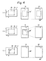
- Figs. 4(a), 4(b) and 4(c) are explanatory views illustrating the conception of printing methods according to the present invention in the relation between the recording medium 2, and the contents of the image memory 19 and the mode of printing data on the printing sheet 22.
- Fig. 4(a) illustrates a first printing method.
- the light-receiving element 16 (Fig. 3) starts scanning the matters to be printed in a direction indicated by an arrow B as the recording medium 2 is moved in a direction indicated by an arrow A. After the completion of scanning of one line, the next line is scanned. Thus the matters to be printed are scanned sequentially line by line.
- the matters thus scanned are written in the image memory 19 in a direction indicated by an arrow C, under the control of the control circuit 18 (Fig. 3).
- the matters, namely, the writings and drawings recorded on the sheet 28 are stored in the image memory 19 as indicated at 28' in Fig.
- Fig. 4(b) illustrates a second printing method according to the present invention.
- the writings and drawings recorded on the sheet 28 are stored in the image memory 19 in the same manner as that of the first printing method, and hence the description the procedure for storing the writings and drawings recorded on the sheet 28 in the image memory 19 will be omitted.
- the writings and drawings recorded on the sheet 28 are stored in the image memory 19 in a mode as indicated at 28' in Fig. 4(b).
- the contents of the image memory 19 are read along a direction indicated at C' under the control of the control circuit 18 (Fig. 3).
- Fig. 4(c) illustrates a third printing method according to the present invention.
- the third printing method is similar to the second printing method, in which only the matters recorded within the sheet 28 are copied.
- the control circuit 18 controls the writing operation so that writing operation is executed only when the scanning operation is performed along a direction indicated by an arrow B' in Fig. 4(c), namely, only when the scanning position is within the sheet 28. Thus only the information within the sheet 28 is written in the image memory 19.
- signals of the information recorded within an area corresponding to a sheet specified by means of a sheet size selection switch 4-1 (Fig. 3) is written in the image memory 19.
- Writing in the image memory 19 is carried out along a direction indicated by an arrow C in Fig.
- a sheet size (for example, AO, Al or the like specified in Japanese Industrial Standards) of the sheet 28 is specified by operating the corresponding sheet size selection switch 4-1 of the operating unit 4, and then a copy switch is depressed. Then, the motor control circuit 20 is actuated to drive the motors 10 and 11 so that the recording medium 2 is unwound from the feed drum 8 and wound on the winding drum 9.
- the writing and drawings recorded on the recording medium 2 are illuminated by the light source 12 immediately before the coresponding portion of the recording medium 2 is wound on the winding drum 9.
- the reflected light is projected through the mirror 14 and the lens 15 on the light-receiving element 16.
- the light signals corresponding to the images of the writings and the drawings projected on the light-receiving element 16 are converted into electric signals, and then the electric signals are transmitted to the control circuit 18.
- the control circuit 18 controls the reading operation so that the data recorded outside an area corresponding to the specified sheet size is skipped, namely data recorded outside the sheet 28 is skipped.
- the recording medium 2 is wound gradually on the winding drum 9 and the reading of the data within the range of the sheet 28 is started, the printing sheet feed motor is started and the printing signals corresponding to the data recorded within the range of the sheet 28 are supplied sequentially to the printing head 25 to print the data read from the sheet 28 on a printing sheet 22. Simultaneously, the printing signals are stored in the image memory 19.
- the image data stored in the image memory 19 is read under the control of the control circuit 18 to produce a plurality of the same copies.
Landscapes
- Engineering & Computer Science (AREA)
- Multimedia (AREA)
- Signal Processing (AREA)
- Drawing Aids And Blackboards (AREA)
- Position Input By Displaying (AREA)
- Editing Of Facsimile Originals (AREA)
Claims (5)
- Tableau d'impression électronique comportant :a) un grand support d'enregistrement (2) destiné à des écritures et des dessins effaçables ;b) une source de lumière (12) destinée à éclairer la surface dudit support d'enregistrement ;c) un élément photoélectrique (16) destiné à convertir l'image desdites écritures et/ou dessins enregistrés sur ledit support d'enregistrement en signaux électriques correspondants ;
caractérisé par :d) une mémoire d'images (19) destinée à stocker des données correspondant auxdits signaux électriques ;e) une tête d'impression (25) destinée à convertir le contenu de ladite mémoire d'images en signaux de motifs correspondants et à imprimer un motif correspondant auxdits signaux de motifs ;f) des feuilles (28) de dimensions inférieures à la dimension dudit support d'enregistrement ; etg) des moyens (29) destinés à fixer l'une quelconque desdites feuilles sur ledit support d'enregistrement. - Tableau d'impression électronique selon la revendication 1, comportant en outre :
des moyens de commande (4-1) destinés à spécifier la dimension d'une feuille (28) à fixer sur ledit support d'enregistrement (2) ; et
des repères (2-1) destinés à indiquer les positions correctes respectives desdites feuilles sur ledit support d'enregistrement. - Tableau d'impression électronique selon la revendication 2, dans lequel lesdits repères (2-1) sont imprimés sur ledit support d'enregistrement.
- Tableau d'impression électronique selon la revendication 2, dans lequel une zone de stockage dans ladite mémoire (19) d'images devant être lue est conçue pour pouvoir être commandée en fonction de la dimension de la feuille (28) spécifiée à l'aide desdits moyens de commande (4-1), et seules les données enregistrées dans ladite feuille sont imprimées.
- Tableau d'impression électronique selon la revendication 2, dans lequel une opération d'écriture pour stocker des données enregistrées sur une feuille (28) est conçue pour pouvoir être commandée en fonction de la dimension de ladite feuille (28) spécifiée à l'aide desdits moyens de commande (4-1), et seules les données enregistrées dans ladite feuille sont lues et imprimées.
Applications Claiming Priority (2)
| Application Number | Priority Date | Filing Date | Title |
|---|---|---|---|
| JP59178468A JPS6157175A (ja) | 1984-08-29 | 1984-08-29 | 電子黒板装置 |
| JP178468/84 | 1984-08-29 |
Publications (3)
| Publication Number | Publication Date |
|---|---|
| EP0173326A2 EP0173326A2 (fr) | 1986-03-05 |
| EP0173326A3 EP0173326A3 (en) | 1988-03-02 |
| EP0173326B1 true EP0173326B1 (fr) | 1992-01-15 |
Family
ID=16049035
Family Applications (1)
| Application Number | Title | Priority Date | Filing Date |
|---|---|---|---|
| EP85110853A Expired - Lifetime EP0173326B1 (fr) | 1984-08-29 | 1985-08-28 | Tableau d'impression électronique |
Country Status (5)
| Country | Link |
|---|---|
| US (1) | US4727431A (fr) |
| EP (1) | EP0173326B1 (fr) |
| JP (1) | JPS6157175A (fr) |
| KR (1) | KR880000428B1 (fr) |
| DE (1) | DE3585187D1 (fr) |
Families Citing this family (28)
| Publication number | Priority date | Publication date | Assignee | Title |
|---|---|---|---|---|
| US4821335A (en) * | 1985-04-05 | 1989-04-11 | Ricoh Company, Limited | Electronic blackboard |
| JPH0773957B2 (ja) * | 1985-12-27 | 1995-08-09 | 沖電気工業株式会社 | 電子黒板装置 |
| USD300150S (en) | 1986-03-11 | 1989-03-07 | Ricoh Company, Ltd. | White board copier |
| JPS63115223A (ja) * | 1986-10-31 | 1988-05-19 | Pentel Kk | 電子黒板 |
| JPS6378475U (fr) * | 1986-11-11 | 1988-05-24 | ||
| JPH089275B2 (ja) * | 1990-10-29 | 1996-01-31 | 松下電器産業株式会社 | 電子黒板装置 |
| EP0694240A4 (fr) * | 1993-02-11 | 1996-06-26 | Polycom Inc | Projecteur interactif de site eloigne |
| US5940049A (en) * | 1995-10-23 | 1999-08-17 | Polycom, Inc. | Remote interactive projector with image enhancement |
| JPH1178369A (ja) * | 1997-09-03 | 1999-03-23 | Plus Kogyo Kk | 表示システム |
| JP2000158887A (ja) * | 1998-11-27 | 2000-06-13 | Matsushita Electric Ind Co Ltd | 電子黒板装置 |
| US7742198B2 (en) * | 2001-09-12 | 2010-06-22 | Seiko Epson Corporation | Image processing apparatus and method |
| US7059785B2 (en) | 2001-09-12 | 2006-06-13 | Seiko Epson Corporation | Composite printer and scan image copying method |
| US7427983B1 (en) | 2002-06-02 | 2008-09-23 | Steelcase Development Corporation | Visual communication system |
| USD593156S1 (en) | 2007-03-16 | 2009-05-26 | Bi-Silque-Artigos Para Casa E Escritorio, S.A. | Memo board |
| USD617834S1 (en) | 2007-03-16 | 2010-06-15 | Bi-Silque-Artigos Para Casa E Escritorio, S.A. | Memo board |
| US9164975B2 (en) | 2008-06-24 | 2015-10-20 | Monmouth University | System and method for viewing and marking maps |
| US20110096091A1 (en) * | 2008-06-24 | 2011-04-28 | Monmouth University | System and method for viewing and marking maps |
| USD683403S1 (en) * | 2011-02-17 | 2013-05-28 | Bi-Silque- Artigos Para Casa e Escritorio, S.A. | Memo board |
| USD671170S1 (en) * | 2012-06-06 | 2012-11-20 | Knoll, Inc. | Marker board |
| JP5796596B2 (ja) | 2013-04-26 | 2015-10-21 | コニカミノルタ株式会社 | 支援方法、支援システム、制御装置、画像形成装置、および支援プログラム |
| USD909474S1 (en) * | 2018-07-10 | 2021-02-02 | Lg Electronics Inc. | Electronic whiteboard |
| USD897432S1 (en) * | 2018-09-24 | 2020-09-29 | Tangerine Ideas, Inc. | Whiteboard |
| USD894276S1 (en) * | 2019-05-14 | 2020-08-25 | CKnapp Sales, Inc. | Whiteboard |
| USD940238S1 (en) * | 2019-06-28 | 2022-01-04 | Lg Electronics Inc. | Stand for electronic whiteboard |
| USD939628S1 (en) * | 2019-06-28 | 2021-12-28 | Lg Electronics Inc. | Electronic whiteboard |
| USD942542S1 (en) * | 2019-06-28 | 2022-02-01 | Lg Electronics Inc. | Electronic whiteboard |
| KR102794393B1 (ko) * | 2024-10-17 | 2025-04-15 | (주)엠트리센 | 가축 생체정보 스캐닝 시스템 |
| KR102799621B1 (ko) * | 2024-10-17 | 2025-04-29 | (주)엠트리센 | 가축 생체정보 스캐닝 시스템 |
Family Cites Families (5)
| Publication number | Priority date | Publication date | Assignee | Title |
|---|---|---|---|---|
| US4125743A (en) * | 1977-06-07 | 1978-11-14 | Bell Telephone Laboratories, Incorporated | Graphics transmission system |
| JPS5540460A (en) * | 1978-09-14 | 1980-03-21 | Fuji Xerox Co Ltd | Image transfer device |
| JPS5629237A (en) * | 1979-08-16 | 1981-03-24 | Dainippon Screen Mfg Co Ltd | Image scanning and recording method |
| JPH0748795B2 (ja) * | 1982-07-09 | 1995-05-24 | 富士写真フイルム株式会社 | 画像入出力装置 |
| US4587568A (en) * | 1983-03-18 | 1986-05-06 | Oki Electric Industry Co., Ltd. | Electronic print board |
-
1984
- 1984-08-29 JP JP59178468A patent/JPS6157175A/ja active Pending
-
1985
- 1985-08-23 US US06/768,819 patent/US4727431A/en not_active Expired - Fee Related
- 1985-08-27 KR KR1019850006187A patent/KR880000428B1/ko not_active Expired
- 1985-08-28 EP EP85110853A patent/EP0173326B1/fr not_active Expired - Lifetime
- 1985-08-28 DE DE8585110853T patent/DE3585187D1/de not_active Expired - Fee Related
Also Published As
| Publication number | Publication date |
|---|---|
| EP0173326A2 (fr) | 1986-03-05 |
| US4727431A (en) | 1988-02-23 |
| DE3585187D1 (de) | 1992-02-27 |
| EP0173326A3 (en) | 1988-03-02 |
| JPS6157175A (ja) | 1986-03-24 |
| KR880000428B1 (ko) | 1988-03-23 |
| KR860001720A (ko) | 1986-03-22 |
Similar Documents
| Publication | Publication Date | Title |
|---|---|---|
| US4727431A (en) | Electronic print board | |
| EP0119856B1 (fr) | Tableau d'écriture électronique | |
| US4626924A (en) | Image forming apparatus | |
| JPH07214826A (ja) | 印刷装置 | |
| JP2562556Y2 (ja) | 手動走査装置の補助装置 | |
| JPH0346611Y2 (fr) | ||
| JP3807471B2 (ja) | 電子黒板 | |
| JPH0374867B2 (fr) | ||
| JP3785746B2 (ja) | 電子黒板 | |
| JPS62101498A (ja) | コピ−再生ボ−ト | |
| CA1095580A (fr) | Traduction non-disponible | |
| JPH0450690Y2 (fr) | ||
| JPH04330846A (ja) | 複写ボード | |
| JPS62292065A (ja) | 小型複写装置 | |
| JPS6381562A (ja) | 文書処理装置 | |
| JPS6354056A (ja) | 電子黒板装置 | |
| JPS6220467A (ja) | 電子黒板装置 | |
| JPH01226273A (ja) | 電子黒板装置 | |
| JPS62200968A (ja) | 電子黒板装置 | |
| JPS60229466A (ja) | 電子黒板装置の連続試験方式 | |
| JPH072438B2 (ja) | 電子黒板装置 | |
| JPS63272270A (ja) | 拡大表示機能付黒板 | |
| JPH0580358B2 (fr) | ||
| JPH01306297A (ja) | 電子黒板装置 | |
| JPH115397A (ja) | 電子黒板 |
Legal Events
| Date | Code | Title | Description |
|---|---|---|---|
| PUAI | Public reference made under article 153(3) epc to a published international application that has entered the european phase |
Free format text: ORIGINAL CODE: 0009012 |
|
| AK | Designated contracting states |
Kind code of ref document: A2 Designated state(s): DE FR GB NL |
|
| 17P | Request for examination filed |
Effective date: 19860814 |
|
| PUAL | Search report despatched |
Free format text: ORIGINAL CODE: 0009013 |
|
| AK | Designated contracting states |
Kind code of ref document: A3 Designated state(s): DE FR GB NL |
|
| 17Q | First examination report despatched |
Effective date: 19901102 |
|
| GRAA | (expected) grant |
Free format text: ORIGINAL CODE: 0009210 |
|
| AK | Designated contracting states |
Kind code of ref document: B1 Designated state(s): DE FR GB NL |
|
| PG25 | Lapsed in a contracting state [announced via postgrant information from national office to epo] |
Ref country code: NL Effective date: 19920115 |
|
| REF | Corresponds to: |
Ref document number: 3585187 Country of ref document: DE Date of ref document: 19920227 |
|
| ET | Fr: translation filed | ||
| NLV1 | Nl: lapsed or annulled due to failure to fulfill the requirements of art. 29p and 29m of the patents act | ||
| PLBE | No opposition filed within time limit |
Free format text: ORIGINAL CODE: 0009261 |
|
| STAA | Information on the status of an ep patent application or granted ep patent |
Free format text: STATUS: NO OPPOSITION FILED WITHIN TIME LIMIT |
|
| 26N | No opposition filed | ||
| PGFP | Annual fee paid to national office [announced via postgrant information from national office to epo] |
Ref country code: FR Payment date: 19960809 Year of fee payment: 12 |
|
| PGFP | Annual fee paid to national office [announced via postgrant information from national office to epo] |
Ref country code: GB Payment date: 19960819 Year of fee payment: 12 |
|
| PGFP | Annual fee paid to national office [announced via postgrant information from national office to epo] |
Ref country code: DE Payment date: 19960906 Year of fee payment: 12 |
|
| PG25 | Lapsed in a contracting state [announced via postgrant information from national office to epo] |
Ref country code: GB Free format text: LAPSE BECAUSE OF NON-PAYMENT OF DUE FEES Effective date: 19970828 |
|
| GBPC | Gb: european patent ceased through non-payment of renewal fee |
Effective date: 19970828 |
|
| PG25 | Lapsed in a contracting state [announced via postgrant information from national office to epo] |
Ref country code: FR Free format text: LAPSE BECAUSE OF NON-PAYMENT OF DUE FEES Effective date: 19980430 |
|
| PG25 | Lapsed in a contracting state [announced via postgrant information from national office to epo] |
Ref country code: DE Free format text: LAPSE BECAUSE OF NON-PAYMENT OF DUE FEES Effective date: 19980501 |
|
| REG | Reference to a national code |
Ref country code: FR Ref legal event code: ST |