EP0174119A2 - Hydraulische Dämpfungseinheit - Google Patents
Hydraulische Dämpfungseinheit Download PDFInfo
- Publication number
- EP0174119A2 EP0174119A2 EP85305781A EP85305781A EP0174119A2 EP 0174119 A2 EP0174119 A2 EP 0174119A2 EP 85305781 A EP85305781 A EP 85305781A EP 85305781 A EP85305781 A EP 85305781A EP 0174119 A2 EP0174119 A2 EP 0174119A2
- Authority
- EP
- European Patent Office
- Prior art keywords
- piston assembly
- flow
- piston
- valve discs
- damping unit
- Prior art date
- Legal status (The legal status is an assumption and is not a legal conclusion. Google has not performed a legal analysis and makes no representation as to the accuracy of the status listed.)
- Granted
Links
Images

Classifications
-
- F—MECHANICAL ENGINEERING; LIGHTING; HEATING; WEAPONS; BLASTING
- F16—ENGINEERING ELEMENTS AND UNITS; GENERAL MEASURES FOR PRODUCING AND MAINTAINING EFFECTIVE FUNCTIONING OF MACHINES OR INSTALLATIONS; THERMAL INSULATION IN GENERAL
- F16F—SPRINGS; SHOCK-ABSORBERS; MEANS FOR DAMPING VIBRATION
- F16F9/00—Springs, vibration-dampers, shock-absorbers, or similarly-constructed movement-dampers using a fluid or the equivalent as damping medium
- F16F9/32—Details
- F16F9/44—Means on or in the damper for manual or non-automatic adjustment; such means combined with temperature correction
- F16F9/46—Means on or in the damper for manual or non-automatic adjustment; such means combined with temperature correction allowing control from a distance, i.e. location of means for control input being remote from site of valves, e.g. on damper external wall
- F16F9/466—Throttling control, i.e. regulation of flow passage geometry
- F16F9/467—Throttling control, i.e. regulation of flow passage geometry using rotary valves
Definitions
- This invention relates to a hydraulic damping unit as specified in the preamble of claim 1, for example as disclosed in US-A-3 827 538.
- various hydraulic dampers i.e. telescopic shock absorbers and struts have been engineered with selectively variable orificing to control oil flow through the piston as it strokes in the cylinder tube to thereby control the action of the vehicle suspension springs associated therewith.
- dampers involve costly and relatively complex blow-off valving and controls, and are not suitable for quantity production.
- the present invention is concerned with a hydraulic damping unit utilising a new and improved deflection valve and valve control system for hydraulic control which eliminates the complexities and costs of prior variable-damping units and provides improved and precision control of fluid flow through the shock absorber piston to vary the rebound characteristics of the damper.
- a hydraulic damping unit in accordance with the present invention is characterised by the features specified in the characterising portion of claim 1.
- a telescopic hydraulic damper incorporates a rotatable selector plate mounted above a fixed orifice plate.
- the selector plate is movable in response to controls to various rotated positions to select orifice size and radial position of the orificing from a centre to control the fluid force and the resulting amount of deflection of a spring disc pack mounted beneath the orifice plate.
- hydraulic damping characteristics are varied and selected for controlling piston velocity and suspension spring damping during rebound, inasmuch as the resulting amount of deflection of the spring disc pack mounted beneath the orifice plate is predetermined to control fluid flow through the piston.
- Orifice plate rotation is externally controlled by means of a rotatable shaft extending through the piston rod from an external, motor-type actuator, although the shaft could alternatively be rotated by an internal motor-type actuator.
- Orificing adjacent to the centre of the valve spring disc pack is selected so that orifice opening is optimized and close to the anchor (fulcrum) point of the spring disc pack. With this orifice selection, the disc pack deflection is low, the flow restriction through the piston is maximized, and resistance to piston movement is high in the rebound mode of operation. This reduces piston velocities and provides for stiffer (harder) ride characteristics that may be desired under certain vehicle operating conditions such as high-speed cornering.
- the orifice size is optimized for medium (intermediate) damping action. This is achieved by moving the open orifices further from the fulcrum point so that plate deflection may be increased and flow through the piston is increased. Under such intermediate condition, the resistance of the fluid within the damper to piston stroking on rebound is reduced: with this reduced resistance, piston velocity increases and the resulting ride is softer.
- the orifice size is optimized for soft ride and moved further from the centre (fulcrum) of the disc pack. Under such conditions, the fluid forces on the spring disc pack will be further from the centre and effect deflection of the disc pack so that the spring-damping characteristics of the shock absorber are reduced. If even softer rides are desired, the number, location and size of the orifices can be engineered to provide for additional flow through the piston with accompanying deflection of the spring disc pack.
- the damper converts rebound motions into heat at selected rates so that road bumps are cushioned as may be desired by the vehicle operator.
- deflection of the spring disc pack can be the same for all settings, and the flow can be controlled by the amount of spring deflection, the size and radius of the orifices from the centre, and the curvature of the backing plate for the spring disc pack.
- a double-acting hydraulic damper 10 operatively mounted between sprung and unsprung components of the vehicle here represented by an upper support plate 12 connected to the vehicle bodywork (sprung mass of the vehicle) and a lower control arm 14 which is mounted to a steering knuckle and road wheel assembly (unsprung mass of the vehicle).
- the damper 10 incorporates an elongate cylinder tube 16 having a conventional base valve 18 secured in the lower end thereof which controls the passage of oil (as hydraulic fluid) between the cylinder tube and a surrounding oil reservoir 20 formed between the cylinder tube and a reservoir tube 22.
- the reservoir tube 22 is closed at its lower end by a base cup 24 on which the base valve 18 is seated.
- a lower mount 26 welded to the exterior of the base cup provides the connection to the control arm 14.
- a valved piston assembly 28 and connected piston rod 30 are operatively mounted for linear stroking movement in the cylinder tube 16 during shock absorber operation.
- the piston rod 30 extends upwardly from the piston assembly 28 through a conventional rod guide 32 mounted in the upper end of the cylinder tube.
- the piston rod 30 further extends through an annular elastomeric seal 34 and through a cup-like seal cover 36 whose peripheral flange fits into and is welded to the upper end of the reservoir tube 22.
- a helical spring 38 seated on the rod guide 32 and around the piston rod 30 yieldably holds the seal 34 against the inner surface of the seal cover 36.
- the upper end of the piston rod 30 extends through a pair of elastomeric mounting discs 40 and 42 and surrounding backing plates 44 and 46 disposed on opposite sides thereof to sandwich the support plate therebetween by the action of a nut 50 threadedly received on the end of the piston rod 30.
- a cup-like upper cover plate 52 through which the piston rod 30 extends is connected to the piston rod immediately below the backing plate 44 by a cylindrical retainer 54 and a co-operating snap ring 56 received in a groove 58 in the piston rod 30.
- the elastomeric mounting discs 40 and 42 being effectively trapped between the upper and lower plates 46 and 44, isolate the piston rod from the vehicle body.
- the piston rod 30 has a central bore 62 for receiving an elongate actuator shaft 64 that extends therethrough.
- the actuator shaft 64 is arranged to be driven by a motor 65, and is operatively connected to valving in the piston assembly described below. As shown, the actuator shaft 64 is rotatably mounted in a cylindrical bearing 66 which is press-fitted within a small-diameter counterbore 68 in the lower end of the piston rod 30. O-ring seals 70 fitted on the actuator shaft 64 below the bearing 66 contact the walls of the counterbore to block the passage of shock absorber oil through the central bore 62 to the exterior of the damper.
- the actuator shaft 64 is retained in the central bore 62 of the piston rod 30 by washers 74 seated against end walls 76 of a larger-diameter counterbore 80 formed in the piston rod, and by a stop ring 82 fitted into a transverse annular groove 84 in the actuator shaft 64 at the lower side of the washer 74. With such a construction, the shaft 64 cannot be inadvertently withdrawn from the piston rod 30.
- the inner end 86 of the piston rod 30 is welded or otherwise fastened to a cylindrical shell-like main body 88 of the piston assembly 28.
- This main body is peripherally bounded by a skirt 90 of Teflon (polytetrafluorethylene) or other suitable plastics material providing low-friction sliding engagement with the inner wall of the cylinder tube 16.
- a rotatable disc-like orifice selector plate 92 Mounted for axial rotational movement within the confines of the main body 88 of the piston assembly 28 is a rotatable disc-like orifice selector plate 92 having an upstanding neck 94 received in the end of a large-diameter counterbore 80 in the lower end of the piston rod 30.
- the main body 88 of the piston assembly 28 houses a cylindrical, relatively thick fixed orifice plate 98 that interfaces with the lower surface of the selector plate 92.
- the orifice plate 98 is peripherally secured therein between an inner locator ring 100 and an inwardly coined lower annular end 102 of the main body 88.
- a valve spring disc pack 104 comprising a series of flat washer-like valve discs 106, 107, 108, 109, 110 and 111 made of spring steel and having decreasing diameters, from the top to the bottom, is mounted adjacent the orifice plate to deflect downwardly to different positions during a rebound stroke in response to the force of jets of hydraulic fluid thereon, to thereby control fluid flow through the selector plate 92 and orifice plate 98 as further described below.
- the spring disc pack 104 is held in an operative position between a contoured fulcrum (backing) plate 112 and the orifice plate 98 by a central rivet 114, as shown in Figure 2.
- the selector plate 92 is rotatably mounted within the cavity of the main body 88.
- An annular wavy return spring 118 operatively mounted between ap inner surface 120 forming the top of the cavity of the main body 88 and the upper surface 122 of the selector plate 92 biases the selector plate into engagement with the orifice plate 98 under certain operating conditions.
- the selector plate 92 is forced upwardly against the bias of the spring 118 so that oil can flow through the piston assembly 28 via outer orifices 123 for checking the compression stroke.
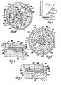
- the selector plate 92 has first and second sets of three arcuately spaced and radially extending openings (windows) 124 and 126 therethrough for controlling the flow of shock absorber fluid through first, second and third sets of orifices 128, 130 and 132 formed in the orifice plate 98.
- the first set of orifices 128 is located at the smallest radial distance from the centre 134 of the orifice plate 98, whereas the second and third sets are respectively located at larger radial distances from the centre 134.
- the damper plate is rotated clockwise or counterclockwise from the Figure 3 position until the windows 126 are aligned with the orifices 128 and 132 and the windows 124 are aligned with the orifices 130 shown in Figure 4, the arrow A thereby being at the soft ride position.
- all orifices are open and the sum of the forces of rebound fluid is moved further out on the lever arm provided by the plates of the disc pack 104.
- the fluid forces on the valve disc pack 104 are highest and the disc pack will be subjected to its greatest deflection on the rebound stroke.
- the selector plate may be selectively rotated to the Figure 5 position so that only the orifices 128 are uncovered by the windows 124, the indicator arrow A thereby being at the hard ride position.
- flow through the windows 124 and orifices 128 will impinge on the spring disc pack 104 at a position closer to the centre 134.
- spring plate deflection is a minimum and rebound valve restriction is a maximum. With this high restriction, resistance to piston movement is increased, and the suspension spring rate is in effect increased, so that the ride is harder.
- Figure 8 is a graph illustrating operation of the preferred embodiment of the invention shown in Figures 1 to 7 with the orifice size and disc pack 104 selected to provide, respectively, high resistance to piston movement for sports-car ride, medium resistance for standard operation and low resistance for highly cushioned boulevard ride.
Landscapes
- Engineering & Computer Science (AREA)
- General Engineering & Computer Science (AREA)
- Mechanical Engineering (AREA)
- Fluid-Damping Devices (AREA)
- Vehicle Body Suspensions (AREA)
Applications Claiming Priority (2)
| Application Number | Priority Date | Filing Date | Title |
|---|---|---|---|
| US64684384A | 1984-09-04 | 1984-09-04 | |
| US646843 | 1984-09-04 |
Publications (3)
| Publication Number | Publication Date |
|---|---|
| EP0174119A2 true EP0174119A2 (de) | 1986-03-12 |
| EP0174119A3 EP0174119A3 (en) | 1987-08-12 |
| EP0174119B1 EP0174119B1 (de) | 1989-07-19 |
Family
ID=24594691
Family Applications (1)
| Application Number | Title | Priority Date | Filing Date |
|---|---|---|---|
| EP19850305781 Expired EP0174119B1 (de) | 1984-09-04 | 1985-08-14 | Hydraulische Dämpfungseinheit |
Country Status (5)
| Country | Link |
|---|---|
| EP (1) | EP0174119B1 (de) |
| JP (1) | JPS6165930A (de) |
| BR (1) | BR8504244A (de) |
| DE (1) | DE3571680D1 (de) |
| ES (1) | ES8609054A1 (de) |
Cited By (9)
| Publication number | Priority date | Publication date | Assignee | Title |
|---|---|---|---|---|
| EP0207409A3 (en) * | 1985-07-02 | 1987-09-02 | Bayerische Motoren Werke Aktiengesellschaft | Valve system for an adjustable hydraulic damper |
| GB2225085A (en) * | 1988-09-27 | 1990-05-23 | Atsugi Unisia Corp | Hydraulic shock absorber |
| GB2225084A (en) * | 1988-09-19 | 1990-05-23 | Atsugi Unisia Corp | Variable-damping-characteristics shock absorber |
| US5085300A (en) * | 1988-10-25 | 1992-02-04 | Tokico Ltd. | Hydraulic damper |
| US5277283A (en) * | 1988-09-19 | 1994-01-11 | Atsugi Unisia Corporation | Variable damping-characteristics shock absorber with adjustable orifice construction variable of fluid flow restriction depending upon fluid pressure difference |
| GB2332727A (en) * | 1997-12-24 | 1999-06-30 | Pilot Precision Dampers Ltd | Damper adjustment mechanism |
| CN109555808A (zh) * | 2012-12-21 | 2019-04-02 | 科尼私人有限公司 | 减震器 |
| CN111502610A (zh) * | 2020-05-29 | 2020-08-07 | 西安石油大学 | 射孔段管柱机械抑振器 |
| CN114857199A (zh) * | 2022-05-07 | 2022-08-05 | 北京理工大学 | 小型可调式大阻尼直线阻尼器 |
Families Citing this family (1)
| Publication number | Priority date | Publication date | Assignee | Title |
|---|---|---|---|---|
| US5193655A (en) * | 1989-09-20 | 1993-03-16 | Atsugia Unisia Corp. | Variable damping force shock absorber with feature of linear and wide range damping force variation depending upon piston stroke speed |
Family Cites Families (6)
| Publication number | Priority date | Publication date | Assignee | Title |
|---|---|---|---|---|
| US3827538A (en) * | 1966-11-09 | 1974-08-06 | F Morgan | Shock absorbers |
| JPS54111064A (en) * | 1978-02-18 | 1979-08-31 | Honda Motor Co Ltd | Damping-force adjusting apparatus in hydraulic shock- absorber |
| JPS55142139A (en) * | 1979-04-23 | 1980-11-06 | Kayaba Ind Co Ltd | Damping force regulator in hydraulic shock absorber |
| GB2111168B (en) * | 1981-11-06 | 1986-07-16 | Tokico Ltd | Hydraulic damper with bypass |
| JPS60151440A (ja) * | 1984-01-13 | 1985-08-09 | Kayaba Ind Co Ltd | 油圧緩衝器 |
| DE3523628A1 (de) * | 1985-07-02 | 1987-01-15 | Bayerische Motoren Werke Ag | Ventilsystem fuer steuerbare, hydraulische schwingungsdaempfer |
-
1985
- 1985-08-14 EP EP19850305781 patent/EP0174119B1/de not_active Expired
- 1985-08-14 DE DE8585305781T patent/DE3571680D1/de not_active Expired
- 1985-09-03 ES ES546672A patent/ES8609054A1/es not_active Expired
- 1985-09-03 BR BR8504244A patent/BR8504244A/pt unknown
- 1985-09-04 JP JP19402185A patent/JPS6165930A/ja active Pending
Cited By (13)
| Publication number | Priority date | Publication date | Assignee | Title |
|---|---|---|---|---|
| EP0207409A3 (en) * | 1985-07-02 | 1987-09-02 | Bayerische Motoren Werke Aktiengesellschaft | Valve system for an adjustable hydraulic damper |
| US5277283A (en) * | 1988-09-19 | 1994-01-11 | Atsugi Unisia Corporation | Variable damping-characteristics shock absorber with adjustable orifice construction variable of fluid flow restriction depending upon fluid pressure difference |
| GB2225084A (en) * | 1988-09-19 | 1990-05-23 | Atsugi Unisia Corp | Variable-damping-characteristics shock absorber |
| GB2225084B (en) * | 1988-09-19 | 1992-09-23 | Atsugi Unisia Corp | Variable-damping-characteristics shock absorber |
| GB2225085A (en) * | 1988-09-27 | 1990-05-23 | Atsugi Unisia Corp | Hydraulic shock absorber |
| US5115892A (en) * | 1988-09-27 | 1992-05-26 | Atsugi Unisia Corporation | Hydraulic shock absorber with piston seal structure for enhancement of initial response |
| GB2225085B (en) * | 1988-09-27 | 1993-03-10 | Atsugi Unisia Corp | Hydraulic shock absorber |
| US5085300A (en) * | 1988-10-25 | 1992-02-04 | Tokico Ltd. | Hydraulic damper |
| GB2332727A (en) * | 1997-12-24 | 1999-06-30 | Pilot Precision Dampers Ltd | Damper adjustment mechanism |
| CN109555808A (zh) * | 2012-12-21 | 2019-04-02 | 科尼私人有限公司 | 减震器 |
| CN111502610A (zh) * | 2020-05-29 | 2020-08-07 | 西安石油大学 | 射孔段管柱机械抑振器 |
| CN111502610B (zh) * | 2020-05-29 | 2021-11-30 | 西安石油大学 | 射孔段管柱机械抑振器 |
| CN114857199A (zh) * | 2022-05-07 | 2022-08-05 | 北京理工大学 | 小型可调式大阻尼直线阻尼器 |
Also Published As
| Publication number | Publication date |
|---|---|
| JPS6165930A (ja) | 1986-04-04 |
| BR8504244A (pt) | 1986-07-01 |
| EP0174119A3 (en) | 1987-08-12 |
| EP0174119B1 (de) | 1989-07-19 |
| DE3571680D1 (en) | 1989-08-24 |
| ES546672A0 (es) | 1986-07-16 |
| ES8609054A1 (es) | 1986-07-16 |
Similar Documents
| Publication | Publication Date | Title |
|---|---|---|
| US4724937A (en) | Hydraulic damper for vehicles with variable deflected disk piston valving | |
| US4685545A (en) | Hydraulic damper for vehicles with variable orifice piston valving for varying damping force | |
| EP0304197B1 (de) | Doppelt wirkender Dämpfer zur Regelung des Fahrzeugfahrverhaltens | |
| US4356898A (en) | Valve assembly and reduced harshness shock absorber embodying the same | |
| EP0294952B1 (de) | Hydraulischer Zwei-Weg-Dämpfer | |
| US5823306A (en) | Stroke dependent damping | |
| US9682605B2 (en) | Variable dampening speed piston head assembly for radio controlled cars shock absorber and method | |
| US4298102A (en) | Shock absorber for vehicle use | |
| US5080205A (en) | Steer-sensitive variable damping strut | |
| US5921360A (en) | Digressive damper valve | |
| EP0174119B1 (de) | Hydraulische Dämpfungseinheit | |
| US5201389A (en) | Method of varying a suspension damping force as a vehicle is steered | |
| US4757884A (en) | Hydraulic damper for vehicle suspension with wide range of two-stage damper curves | |
| US5251927A (en) | Steer-sensitive hydraulic shock absorber and method | |
| US5706919A (en) | Alternating state pressure regulation valved damper | |
| GB2199118A (en) | Hydraulic damper | |
| US6533085B2 (en) | Modular blow-off valve for automotive damper | |
| EP0186324B1 (de) | Hydraulischer Stossdämpfer für Fahrzeug | |
| US6276499B1 (en) | Hydraulic shock absorbers | |
| WO2020069440A1 (en) | Damper with flexible floating disc | |
| JPH08291836A (ja) | 液圧緩衝装置 | |
| EP0196797B1 (de) | Hydraulischer Dämpfer | |
| KR20090100545A (ko) | 쇽업소버 | |
| WO2026055009A1 (en) | Base valve with open bleed tuning capabilities | |
| KR100376151B1 (ko) | 쇽압쇼바의가변식유압댐퍼 |
Legal Events
| Date | Code | Title | Description |
|---|---|---|---|
| PUAI | Public reference made under article 153(3) epc to a published international application that has entered the european phase |
Free format text: ORIGINAL CODE: 0009012 |
|
| 17P | Request for examination filed |
Effective date: 19850829 |
|
| AK | Designated contracting states |
Kind code of ref document: A2 Designated state(s): DE FR GB IT |
|
| PUAL | Search report despatched |
Free format text: ORIGINAL CODE: 0009013 |
|
| AK | Designated contracting states |
Kind code of ref document: A3 Designated state(s): DE FR GB IT |
|
| 17Q | First examination report despatched |
Effective date: 19880718 |
|
| ITF | It: translation for a ep patent filed | ||
| GRAA | (expected) grant |
Free format text: ORIGINAL CODE: 0009210 |
|
| AK | Designated contracting states |
Kind code of ref document: B1 Designated state(s): DE FR GB IT |
|
| PGFP | Annual fee paid to national office [announced via postgrant information from national office to epo] |
Ref country code: GB Payment date: 19890731 Year of fee payment: 5 |
|
| REF | Corresponds to: |
Ref document number: 3571680 Country of ref document: DE Date of ref document: 19890824 |
|
| ITTA | It: last paid annual fee | ||
| PGFP | Annual fee paid to national office [announced via postgrant information from national office to epo] |
Ref country code: FR Payment date: 19890905 Year of fee payment: 5 |
|
| PGFP | Annual fee paid to national office [announced via postgrant information from national office to epo] |
Ref country code: DE Payment date: 19890925 Year of fee payment: 5 |
|
| ET | Fr: translation filed | ||
| PLBE | No opposition filed within time limit |
Free format text: ORIGINAL CODE: 0009261 |
|
| STAA | Information on the status of an ep patent application or granted ep patent |
Free format text: STATUS: NO OPPOSITION FILED WITHIN TIME LIMIT |
|
| 26N | No opposition filed | ||
| PG25 | Lapsed in a contracting state [announced via postgrant information from national office to epo] |
Ref country code: GB Effective date: 19900814 |
|
| GBPC | Gb: european patent ceased through non-payment of renewal fee | ||
| PG25 | Lapsed in a contracting state [announced via postgrant information from national office to epo] |
Ref country code: FR Effective date: 19910430 |
|
| PG25 | Lapsed in a contracting state [announced via postgrant information from national office to epo] |
Ref country code: DE Effective date: 19910501 |
|
| REG | Reference to a national code |
Ref country code: FR Ref legal event code: ST |