EP0174604A2 - Wand-, Decken- und/oder Bodenausbildung - Google Patents
Wand-, Decken- und/oder Bodenausbildung Download PDFInfo
- Publication number
- EP0174604A2 EP0174604A2 EP85111207A EP85111207A EP0174604A2 EP 0174604 A2 EP0174604 A2 EP 0174604A2 EP 85111207 A EP85111207 A EP 85111207A EP 85111207 A EP85111207 A EP 85111207A EP 0174604 A2 EP0174604 A2 EP 0174604A2
- Authority
- EP
- European Patent Office
- Prior art keywords
- layer
- heating element
- ceiling
- substrate
- resistance heating
- Prior art date
- Legal status (The legal status is an assumption and is not a legal conclusion. Google has not performed a legal analysis and makes no representation as to the accuracy of the status listed.)
- Granted
Links
Images

Classifications
-
- F—MECHANICAL ENGINEERING; LIGHTING; HEATING; WEAPONS; BLASTING
- F24—HEATING; RANGES; VENTILATING
- F24D—DOMESTIC- OR SPACE-HEATING SYSTEMS, e.g. CENTRAL HEATING SYSTEMS; DOMESTIC HOT-WATER SUPPLY SYSTEMS; ELEMENTS OR COMPONENTS THEREFOR
- F24D13/00—Electric heating systems
- F24D13/02—Electric heating systems solely using resistance heating, e.g. underfloor heating
- F24D13/022—Electric heating systems solely using resistance heating, e.g. underfloor heating resistances incorporated in construction elements
- F24D13/024—Electric heating systems solely using resistance heating, e.g. underfloor heating resistances incorporated in construction elements in walls, floors, ceilings
-
- H—ELECTRICITY
- H05—ELECTRIC TECHNIQUES NOT OTHERWISE PROVIDED FOR
- H05B—ELECTRIC HEATING; ELECTRIC LIGHT SOURCES NOT OTHERWISE PROVIDED FOR; CIRCUIT ARRANGEMENTS FOR ELECTRIC LIGHT SOURCES, IN GENERAL
- H05B3/00—Ohmic-resistance heating
- H05B3/20—Heating elements having extended surface area substantially in a two-dimensional [2D] plane, e.g. plate-heater
- H05B3/22—Heating elements having extended surface area substantially in a two-dimensional [2D] plane, e.g. plate-heater non-flexible
- H05B3/28—Heating elements having extended surface area substantially in a two-dimensional [2D] plane, e.g. plate-heater non-flexible heating conductor embedded in insulating material
- H05B3/283—Heating elements having extended surface area substantially in a two-dimensional [2D] plane, e.g. plate-heater non-flexible heating conductor embedded in insulating material the insulating material being an inorganic material, e.g. ceramic
-
- H—ELECTRICITY
- H05—ELECTRIC TECHNIQUES NOT OTHERWISE PROVIDED FOR
- H05B—ELECTRIC HEATING; ELECTRIC LIGHT SOURCES NOT OTHERWISE PROVIDED FOR; CIRCUIT ARRANGEMENTS FOR ELECTRIC LIGHT SOURCES, IN GENERAL
- H05B3/00—Ohmic-resistance heating
- H05B3/20—Heating elements having extended surface area substantially in a two-dimensional [2D] plane, e.g. plate-heater
- H05B3/22—Heating elements having extended surface area substantially in a two-dimensional [2D] plane, e.g. plate-heater non-flexible
- H05B3/28—Heating elements having extended surface area substantially in a two-dimensional [2D] plane, e.g. plate-heater non-flexible heating conductor embedded in insulating material
- H05B3/286—Heating elements having extended surface area substantially in a two-dimensional [2D] plane, e.g. plate-heater non-flexible heating conductor embedded in insulating material the insulating material being an organic material, e.g. plastic
-
- Y—GENERAL TAGGING OF NEW TECHNOLOGICAL DEVELOPMENTS; GENERAL TAGGING OF CROSS-SECTIONAL TECHNOLOGIES SPANNING OVER SEVERAL SECTIONS OF THE IPC; TECHNICAL SUBJECTS COVERED BY FORMER USPC CROSS-REFERENCE ART COLLECTIONS [XRACs] AND DIGESTS
- Y02—TECHNOLOGIES OR APPLICATIONS FOR MITIGATION OR ADAPTATION AGAINST CLIMATE CHANGE
- Y02B—CLIMATE CHANGE MITIGATION TECHNOLOGIES RELATED TO BUILDINGS, e.g. HOUSING, HOUSE APPLIANCES OR RELATED END-USER APPLICATIONS
- Y02B30/00—Energy efficient heating, ventilation or air conditioning [HVAC]
Definitions
- the invention relates to a wall, ceiling and / or floor formation, consisting of a plastered or, if necessary, plastered substrate and a covering layer and a resistance heating element arranged between the covering layer and the substrate, which consists of a polyester cover layer, one with supply and discharge lines provided conductive intermediate layer, e.g. B. a graphite and / or carbon black resistance layer, and a polyester underlayer.
- Standard pure radiant heaters installed in rooms only have a locally very limited radiation area and work at high temperatures.
- the prior art also includes underfloor heating systems in which heating coils acted upon by liquid heat transfer medium, but also electrical heating conductors, are accommodated in the screed or below the top floor covering.
- Underfloor heating systems are comparatively cumbersome and expensive to build and require comparatively complex controls.
- flat structures e.g. B. from DE-B 16 15 257 known electric heating film already belong to the prior art.
- Other teachings are to embed resistance layers, but also conductive metal foils between insulating layers or foils and thus to form flat heating elements, for. B. for a floor heating and air conditioning system to come (DE-A 30 26 098 or DE-A 23 06 271).
- the object of the invention is to propose a wall, ceiling or floor formation on a given or, if necessary, plastered surface with the help of design elements of room boundaries, which as such can serve to heat the room provided with it.
- the covering layer consists of ceramic moldings, in particular plates, and the resistance heating element is glued on with the aid of an adhesive composition which adheres both to the substrate and to the free polyester surface of the cover layer.
- German patent application P 34 07 444.9 already suggests a ceramic molded body which is provided with an electrical resistance coating on the side facing away from its visible side, which has a uniform electrical and thermal conductivity over the entire coating surface. It has also already been considered that the electrical resistance coating consists of an electrical resistance film which is at least locally fixed on the side of the molded body facing away from the visible body, preferably glued flat.
- the proposal for the invention differs from the fact that the resistance film, for example unrolled from a roll, is laid out over the entire surface to be covered and the corresponding connection elements are connected to one another, the ceramic material in the desired manner on this overall covering of the floor, ceiling or wall surface Orientation is applied.
- a further development of the invention consists in the fact that the cover layer and the lower layer of the resistance film are welded together locally with the displacement of the resistance layer, which is forced by the application of pressure, by the action of ultrasound. This measure is sometimes necessary if it turns out that the bond between the resistance layer and the top or bottom layer is not sufficient, for example, to hang ceramic plates on walls or even on ceilings. In such a case, the connection of the top layer and the bottom layer in places means that these two layers cannot be detached from the resistance layer and thus the resistance layer cannot be separated, which could result in the ceramic covering falling off.
- a resistance heating element must be provided between the sub-surface and the covering, which is locally perforated, for example punched through, the sub-surface and covering made of ceramic plates using one of the holes penetrating, at least adhered to the ceramic plates and to the substrate adhesive.
- the hole edges of the top and bottom layers are welded together.
- Another possibility of isolating the hole boundary walls is to insert a piece of tubing consisting of an electrically insulating material into the holes, which, if necessary, is connected in a suitable manner at least in the edge region of the top and bottom layers.
- the resistance heating element is divided in terms of area while leaving areas not covered by it, the link surfaces are electrically connected to one another and local openings of the resistance heating element are provided in the areas not covered by the resistance heating element.
- the method according to the invention for covering a substrate is expediently carried out in such a way that an adhesive is applied to the plastered surface, if necessary, which adheres to this surface.
- a resistance heating element of the type specified which has been pretreated with a primer, is applied, the primer preparing the polyester surface of the resistance heating element in such a way that adhesion with the adhesive applied to the substrate is ensured.
- a primer is again applied to the still free surface of the resistance heating element and then the plate material is either glued on by applying an adhesive to the primer or the plate material has been pretreated accordingly with the adhesive.
- a modification of this method, in which it is not necessary to use comparatively complicated adhesive systems, is that a resistance heating element is used which is locally broken through, e.g. B. is punched so that now this resistance heating element is simply applied to a surface that is provided with an adhesive that adheres to both the surface and the ceramic plate material. If the heating element is now placed on this surface provided with such an adhesive, and it may have to be tacked locally, then plate material provided with adhesive can be attached accordingly, the adhesive exposed in the openings being connected to the adhesive on the back of the plate material and as a result, both the plate material and the resistance heating element are appropriately held over the adhesive penetrating the punched holes.
- connections 11 1, tracks 1, 2, 3 of a resistance heating element are designed on a base surface corresponding to the drawing area, for example, which have copper strips 4, 5, 6, 7, 8 and 9 along their edges.
- the two copper strips 4 and 9 are supplied with current by a current source indicated schematically at 10, so that the resistance heating elements heat up accordingly.
- the connection between elements 1 and 2 or 2 and 3 is established by connection connections 11.
- the possible configuration of the conductive intermediate layer of the resistance heating element in a configuration in which it is divided in terms of area while leaving areas not covered by it is not shown individually. It can e.g. B. a meandering arrangement of the resistance layer or a breakdown of the same into a plurality of flat, but electrically connected or subsequently to be connected sub-layers in the form of tapes, elk pieces or the like. Choosing the appropriate one Pattern is based on local conditions and / or technical requirements.
- comparatively large-area ceramic plates 12 to 23 are designed on the resistance heating elements, the format and circumferential design of which can be chosen as desired.
- the subsurface is designated 31, which can optionally be plastered. It can be a wall, a ceiling or a floor.
- the element 33 consists of a polyester cover layer 36, a resistance layer 37 and an underlayer 38.
- the cover layer and the underlayer are brought into contact locally at 39 and 40 with displacement of the resistance layer 37 and are connected to one another, for example, by ultrasonic welding.
- the adhesion between the polyester film surface and the substrate or ceramic plate must be achieved with the help of an adhesive that is able to create a bond between these different surfaces.
- connection is preferably carried out in such a way that the adhesive 32 is first applied to the substrate 31, whereupon the free surface of the cover layer 36 is treated with a primer and, after this treatment, the resistance heating element 33 is attached to the substrate 31. Now the surface of the underlayer, which is now still exposed, is coated with a primer and then the plate 35 provided with the adhesive 34 is placed on it.
- the adhesive is, for example, the one under the trade name PCI Lastoment 2 known product.
- a primer that can be used for this purpose is commercially available under the trade name Collastic FH.
- 61 denotes a ceramic plate, on the side 65 of which faces away from the visible side 64, an adhesive layer 62 is applied.
- the resistance heating element 63 On this adhesive layer 62, which only needs to adhere to the plate 61, there is the resistance heating element 63, the structure of which corresponds to that of the resistance heating elements 33 and 43, so that it does not need to be described in more detail here.
- the resistance heating element is in a z. B. from Fig. 1 apparent punched out rivets 66 and 67 are inserted from an insulating material in the resulting holes.
- the rivet 67 reveals a central wall 68 and thus that in this case, too, adhesive can penetrate into the blind holes formed in this way both from the adhesive layer 62 and from an adhesive adhesive 62a attached to a base 69, and thus already sufficient fixing of the plate 61 can be reached on the substrate 69 via the adhesive 62 or 62a.
- Fig. 5 shows a plate 71 ' with adhesive layer 72 and resistance heating element 73, in which holes are punched.
- the upper punched hole is covered with a firmly fitting hose or tube piece 74, which protrudes somewhat at the ends and insulates the conductive resistance layer 75.
- a piece of hose or tube 76 is inserted, which is glued in at 77. This also allows good insulation of the resistance layer in the punched hole area where the adhesive penetrates into the punched hole.
- Fig. 6 shows part of a plate 81 with adhesive layer 82 and resistance heating element 83.
- the upper punched hole is fitted with a fitted, rather thick-walled hollow plug 84, which may have resulted from a full plug 85 (see lower punched hole) by such a the insertion into the punched hole, which does not necessarily have to take place after the film has been stuck onto the plate, is drilled out accordingly.
- This drilling is symbolically indicated by the drill 86.
Landscapes
- Engineering & Computer Science (AREA)
- Chemical & Material Sciences (AREA)
- General Engineering & Computer Science (AREA)
- Thermal Sciences (AREA)
- Combustion & Propulsion (AREA)
- Mechanical Engineering (AREA)
- Physics & Mathematics (AREA)
- Ceramic Engineering (AREA)
- Inorganic Chemistry (AREA)
- Central Heating Systems (AREA)
- Building Environments (AREA)
- Finishing Walls (AREA)
- Glass Compositions (AREA)
- Surface Heating Bodies (AREA)
- Load-Bearing And Curtain Walls (AREA)
Abstract
Description
- Die Erfindung betrifft eine Wand-, Decken- und/oder Bodenausbildung, bestehend aus einem gegebenen- bzw. erforderlichenfalls verputzten Untergrund und einer Belagschicht sowie einem zwischen Belagschicht und Untergrund angeordnetem Widerstandsheizelement, das sich aus einer Polyester-Deckschicht, einer mit Zu- und Ableitungen versehenen leitenden Zwischenschicht, z. B. einer Graphit- und/ oder Ruß-Widerstandsschicht, und einer Polyester-Unterschicht zusammensetzt.
- Es ist bekannt, Räume mittels Raumheizkörpern zu beheizen, die im allgemeinen unterhalb von Fensteröffnungen angebracht sind, damit die von Ihnen erwärmte Raumluft über die Fensteröffnungen hochsteigt und so einen Warmluftvorhang vor der Fensteröffnung erzeugt. Auch bei an Wänden aufgestellten Heizkörpern entsteht eine Luftbewegung vom Boden zur Decke des mit ihnen beheizten Raumes, wobei die vom Heizkörper in den Raum abgestrahlte Wärme nur eine geringe Rolle spielt.
- In Räumen angebrachte übliche reine Strahlungsheizkörper besitzten nur einen örtlich sehr begrenzten Strahlungsbereich und arbeiten mit hohen Temperaturen.
- Zum Stande der Technik gehören ferner Fußbodenheizungen, bei denen im Estrich oder unterhalb des obersten Bodenbelages mit flüssigem Wärmeträger beaufschlagte Heizschlangen, aber auch elektrische Heizleiter untergebracht sind. Fußbodenheizungen sind im Aufbau jedoch vergleichsweise umständlich und teuer und bedürfen einer vergleichsweise aufwendigen Steuerung.
- Auch flächige Gebilde, z. B. ein aus der DE-B 16 15 257 bekannt gewordener elektrischer Heizfilm gehören bereits zum Stande der Technik. Andere Lehren gehen dahin, Widerstandsschichten, aber auch leitende Metallfolien zwischen isolierende Schichten oder Folien einzubetten und so zu flächigen Heizelementen z. B. für eine Fußboden-Wärme-Klima-Anlage zu kommen (DE-A 30 26 098 oder auch DE-A 23 06 271).
- Keine dieser Lehren offenbart aber eine Möglichkeit, Gestaltungselemente der Raumbegrenzung selbst so auszubilden, daß sie einzeln, in Gruppen oder als die gesamte Raumbegrenzung bzw. eines wesentlichen Teiles davon die Aufgabe der Beheizung des Raumes oder eines zu erwärmenden bzw. warmzuhaltenden Teiles der Raumumgrenzung übernehmen können.
- Aus einem Prospekt, herausgegeben von der Firma Canespa KG, 3005 Hemmingen-Westerfeld, Gutenbergstraße 13, im Jahre 1957, läßt sich bereits ein drahtloses Heizsystem "Canespa-Therm" entnehmen, bei dem auf der Rückseite von Formkörpern, und zwar von keramischen Platten eine Heizlackschicht als elektrische Widerstandsbeschichtung aufgebracht ist. Diese Heizlackschicht ist durch einen Polyurethanschaumkörper abgedeckt. Dieses System konnte sich jedoch nicht durchsetzen, da es immer wieder zu örtlichen überhitzungen mit daraus resultierenden schädlichen Weiterungen kam, die sogar zur Gefährdung von Personen und Sachen führten.
- Aufgabe der Erfindung ist es, eine Wand-, Decken- oder Bodenausbildung auf einem gegebenen- bzw. erforderlichenfalls verputzten Untergrund mit Hilfe von Gestaltungselementen von Raumumgrenzungen vorzuschlagen, die als solche der Beheizung des mit ihr versehenen Raumes dienen kann.
- Diese Aufgabe wird erfindungsgemäß dadurch gelöst, daß die Belagschicht aus keramischen Formkörpern, insbesondere Platten besteht und das Widerstandsheizelement mit Hilfe einer Klebmittelzusammensetzung, die sowohl am Untergrund als auch an der freien Polyester-Oberfläche der Deckschicht haftet, aufgeklebzisch. während die keramischen Form-
- körper auf der freien Oberfläche der Polyester-Unterschicht mit Hilfe einer sowohl an der Oberfläche dieser Polyester-Unterschicht als auch an der Sichtseite abgewendeten Seite der keramischen Formkörper haftenden Klebmittelzusammensetzung aufgeklebt sind.
- In der deutschen Patentanmeldung P 34 07 444.9 wird bereits ein keramischer Formkörper vorgeschlagen, der auf der seiner Sichtseite abgewendeten Seite mit einer elektrischen Widerstandsbeschichtung versehen ist, die über die gesamte Beschichtungsfläche eine gleichmäßige elektrische und thermische Leitfähigkeit aufweist. Dabei ist auch bereits in Erwägung gezogen, daß die elektrische Widerstandsbeschichtung aus einer elektrischen Widerstandsfolie besteht, die auf der der Sichtseite des Formkörpers abgewendeten Seite desselben wenigstens örtlich fixiert, vorzugsweise flächig aufgeklebt ist.
- Der Erfindungsvorschlag unterscheidet sich davon dadurch, daß die Widerstandsfolie, beispielsweise von einer Rolle abgerollt, über die gesamte zu bedeckende Oberfläche ausgelegt wird und die entsprechenden Anschlußelemente miteinander verbunden werden, wobei auf diese Gesamtabdeckung der Boden-, Decken- oder Wandfläche das keramjsche Material in gewünschter Orientierung aufgebracht wird.
- Eine Weiterbildung der Erfindung besteht darin, daß die Deckschicht und die Unterschicht der fiderstandsfolie örtlich unter durch Druckaufbringung erzwungener Verdrängung der Widerstandsschicht miteinander durch Ultraschalleinwirkung verschweißt sind. Diese Maßnahme ist mitunter dann erforderlich, wenn sich herausstellt, daß die Bindung zwischen Widerstandsschicht und Deckschicht bzw. Unterschicht nicht ausreicht, um beispielsweise keramische Platten an Wänden oder gar an Decken aufzuhängen. In einem solchen Fall wird durch die stellenweise Verbindung von Deckschicht und Unterschicht erreicht, daß es nicht zu einem Ablösen dieser beiden Schichten von der Widerstandsschicht und damit zu eire- Auftrennen der Widerstandsschicht kommen kann, was ein Abfallen des Keramischen Belages zur Folge haben könnte.
- Will man mit üblichen keramischen Klebern arbeiten, die in der Lage sind, die keramischen Platten unmittelbar mit dem gegebenen- oder erforderlichenfalls verputzten Untergrund zu verbinden, dann muß man in weiterer Ausbildung der Erfindung zwischen Untergrund und Belag ein Widerstandsheizelement vorsehen, die örtlich durchbrochen, beispielsweise durchstanzt ist, wobei Untergrund und Belag aus keramischen Platten mittels eines die Löcher durchsetzenden, wenigstens an den keramischen Platten und am Untergrund haftenden Klebers miteinander verbunden sind. Um Streuströme im Bereich der Löcher zu verhindern, ist es vorteilhaft, wenn in weiterer Ausbildung der Erfindung die Lochränder von Deck- und Unterschicht miteinander verschweißt sind.
- Man kann aber auch in die Löcher jeweils einen aus elektrisch isolierendem Material bestehenden Niet, vorzugsweise einen Hohlniet einsetzen. Bei Verwendung eines Vollniets muß dieser selbstverständlich nachträglich ausgebohrt werden.
- Eine andere Möglichkeit der Isolierung der Lochbegrenzungswände besteht darin, jeweils ein aus einem elektrisch isolierenden Material bestehendes Schlauchstück in die Löcher einzusetzen, das erforderlichenfalls wenigstens im Randbereich von Deck- und Unterschicht mit diesen in geeigneter Weise verbunden ist.
- Ferner besteht die Möglichkeit, in die Löcher jeweils einen Isolierstopfen einzusetzen oder einzugießen, der dann, wenn es sich um einen Vollpfropfen handelt, so ausgebohrt werden muß, daß für die Kleberschichten auf dem Untergrund und der Plattenrückseite Verankerungsstellen entstehen.
- Besonders vorteilhaft kann es sein, wenn gemäß einer abgeänderten Ausführungsform der Erfindung das Widerstandsheizelement unter Belassung von von ihm nicht abgedeckter Bereiche flächenmäßig gegliedert ist, die Gliedflächen untereinander elektrisch in Verbindung stehen und in den von dem Widerstandsheizelement nicht abgedeckten Bereichen örtlich Durchbrechungen des Widerstandsheizelementes vorgesehen sind.
- Das erfindungsgemäße Verfahren zur Verkleidung eines Untergrundes, wie einer Wand, einer Decke und eines Bodens mit keramischen Platten wird zweckmäßig so durchgeführt, daß auf den gegebenen- bzw. erforderlichenfalls verputzten Untergrund ein Kleber aufgetragen wird, der auf diesem Untergrund haftet. Dann wird ein auf der anzuklebenden Oberfläche mit einem Primer vorbehandeltes Widerstandsheizelement der angegebenen Art aufgebracht, wobei der Primer die Polyesteroberfläche des-Widerstandsheizelementes so aufbereitet, daß eine Haftung mit dem auf dem Untergrund aufgebrachten Kleber gewährleistet ist. Nunmehr wird auf die noch freie Oberfläche des Widerstandsheizelementes wiederum ein Primer aufgebracht und dann wird das Plattenmaterial entweder dadurch aufgeklebt, daß auf dem Primer ein Kleber aufgebracht wird oder das Plattenmaterial entsprechend mit dem Kleber vorbehandelt ist.
- Eine Abänderung dieses Verfahrens, bei der es nicht erforderlich ist, vergleichsweise komplizierte Klebersysteme zu verwenden, besteht darin, daß man ein Widerstandsheizelement verwendet, das örtlich durchbrochen, z. B. durchstanzt ist, so daß nunmehr dieses Widerstandsheizelement einfach auf eine Untergrundfläche aufgebracht wird, die mit einem Kleber versehen ist, der sowohl auf dem Untergrund als auch dem keramischen Plattenmaterial haftet. Wird nunmehr auf diese mit einem solchen Kleber versehene Untergrundfläche das Heizelement aufgelegt, wobei es gegebenenfalls örtlich geheftet werden muß, dann kann entsprechend mit Kleber versehenes Plattenmaterial angebracht werden, wobei sich der in den Durchbrechungen freiliegende Kleber mit dem Kleber auf der Rückseite des Plattenmaterials verbindet und dadurch sowohl das Plattenmaterial als auch über den die Stanzlöcher durchsetzenden Kleber das Widerstandsheizelement entsprechend festgehalten werden.
- Die Zeichnung zeigt in
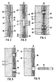
- Fig. 1 eine Draufsicht auf eine Wandausbildung, bei der aufgelegte Keramikplatten lediglich schematisch durch gestrichelte Linien angedeutet sind;
- Fig. 2 einen vergrößerten Teilquerschnitt durch die Anordnung längs der Linie II-II der Fig. 1;
- Fig..3 einen vergrößerten Teilquerschnitt durch die Anordnung nach Fig. 1 längs der Linie III-III der Fig. 1, jedoch mit einer anderen Ausführungsform der Wandausbildung.
- Fig. 4 einen stark vergrößerten Teilschnitt-durch die Platte nach Fig. 3 mit weiteren Abänderungen im Aufbau;
- Fig. 5 einen stark vergrößerten Teilschnitt durch die Platte nach Fig. 3, mit weiteren Abänderungen im Aufbau; und in
- Fig. 6 eine ebenfalls mögliche weitere Abänderung mit der Andeutung eines Verfahrensschrittes.
- Nach Fig. 1 sind auf einer beispielsweise der Zeichenfläche entsprechenden Grundfläche Bahnen 1, 2, 3 eines Widerstandsheizelementes ausgelegt, die längs ihrer Kanten Kupferbänder 4, 5, 6, 7, 8 und 9 aufweisen. Der beiden Kupferbändern 4 und 9 wird von einer bei 10 schematisch angedeuteten Stromquelle Strom zugeführt, so daß sich die Widerstandsheizelemente entsprechend aufheizen. Die Verbindung zwischen den Elementen 1 und 2 bzw. 2 und 3 ist durch Verbindungsanschlüsse 11 hergestellt.
- Die mögliche Ausgestaltung der leitenden Zwischenschicht des Widerstandsheizelementes in einer Ausbildung, bei der es unter Belassung von von ihr nicht abgedeckten Bereichen flächenmäßig gegliedert ist, ist ir einzelnen nicht dargestellt. Es kann sich z. B. um eine mäanderartige Anordnung der Widerstandsschicht oder um eine Aufgliederung derselben in mehrere flächige, aber elektrisch miteinander verbundene oder nachträglich noch zu verbindende Teilschichten in Form von Bändern, Elektenstücken od. dgl. handeln. Die Auswahl des entsprechenden Musters richtet sich nach den örtlichen Gegebenheiten und/oder den technischen Erfordernissen.
- Auf den Aufbau der einzelnen Widerstandsheizelemente wird später im Zusammenhang mit der Beschreibung der Fig. 2 und 3 noch näher eingegangen werden.
- Auf den Widerstandsheizelementen sind beim Ausführungsbeispiel vergleichsweise großflächige keramische Platten 12 bis 23 ausgelegt, deren Format und Umfangsgestaltung beliebig gewählt werden kann.
- In Fig. 2 ist mit 31 der Untergrund bezeichnet, der gegebenenfalls verputzt sein kann. Es kann sich um eine Wand, um eine Decke oder auch um einen Boden handeln.
- Auf diesem Untergrund befindet sich eine Kleberschicht 32, auf der das Widerstandsheizelement 33 verlegt ist. Dieses Element ist mit einer weiteren Kleberschicht 34 abgedeckt, mit deren Hilfe die keramische Platte 35 an am Element 33 befestigt ist. Das Element 33 besteht aus einer Polyester-Deckschicht 36, einer Widerstandsschicht 37 und einer Unterschicht 38. Beim wiedergegebenen Ausführungsbeispiel sind die Deckschicht und die Unterschicht örtlich bei 39 und 40 unter Verdrängung der Widerstandsschicht 37 miteinander in Berührung gebracht und beispielsweise durch Ultraschallschweißen miteinander verbunden. Die Haftung zwischen Polyester-Folienoberfläche und Untergrund bzw. keramischer Platte muß mit Hilfe eines Klebers bewirkt werden, der eine Bindung zwischen diesen unterschiedlichen Flächen herzustellen vermag. Vorzugsweise erfolgt die Verbindung so, daß zuerst der Kleber 32 auf den Untergrund 31 aufgebracht wird, worauf die freie Oberfläche der Deckschicht 36 mit einem Primer behandelt und nach dieser Behandlung das Widerstandsheizelement 33 an dem Untergrund 31 befestigt. Nunmehr wird die jetzt noch freiliegende Oberfläche der Unterschicht mit einem Primer überstrichen und anschließend die mit dem Kleber 34 versehene Platte 35 aufgelegt.
- Dei dem Kleber handelt es sich beispielsweise um das unter dem Handelsnamen PCI-Lastoment 2 bekannte Produkt. Ein dazu brauchbarer Primer ist unter der Handelsbezeichnung Collastic FH im Handel erhältlich.
- Bei der Ausführungsform, wie sie schematisch in Fig. 3 angedeutet ist, bedarf es keiner Verwendung eines Spezialklebers. Es genügt die Verwendung eines Klebers, der in der Lage ist, den Untergrund mit der keramischen Platte zu verbinden. In Fig. 3 ist mit 41 der Untergrund bezeichnet, auf den ein Kleber 42 der angegebenen Art aufgebracht ist. Dann schließt sich das Widerstandsheizelement 43 an. Dieses Element besteht wie das Element 33 aus einer Deckschicht 44, einer Widerstandsschicht 45 und einer Unterschicht 46. Dieses Widerstandsheizelement 43 ist örtlich wie in Fig. 1 durch die kleinen Kreise 24 angedeutet ausgestanzt. Das Stanzloch ist in Fig. 3 mit 47 bezeichnet. In dieses Stanzloch dringt sowohl Kleber 42 als auch Kleber 48 ein, der auf die Platte 49 aufgetragen ist. Die Zusammentreffstelle der beiden Kleberschichten ist durch die Linie 50 schematisch angedeutet. Vorzugsweise erfolgt das Stanzen mit Hilfe eines erwärmten Stanzstempels, so daß die Ränder der Deckschicht und der Unterschicht bei 51 miteinander verschweißt sind und damit die Widerstandsschicht 45 nicht mit dem Kleber im Stanzloch in Berührung kommen kann.
- Bei der Ausführungsform nach Fig. 4 bezeichnet 61 eine keramische Platte, auf deren der Sichtseite 64 abgewendeten Seite 65 eine Kleberschicht 62 aufgebracht ist. Auf dieser Kleberschicht 62, die nur an der Platte 61 zu haften braucht, befindet sich das Widerstandsheizelement 63, dessen Aufbau der der Widerstandsheizelemente 33 und 43 entspricht, so daß er hier nicht mehr näher beschrieben zu werden braucht. Das Widerstandsheizelement ist in einem z. B. aus Fig. 1 ersichtlichen Raster ausgestanzt und in die entstandenen Löcher sind Niete 66 bzw. 67 aus einem isolierenden Material eingesetzt. Der Niet 67 läßt eine Mittelwand 68 und damit erkennen, daß auch in diesem Fall Kleber sowohl aus der Klebmittelschicht 62 als auch aus einer an einem Untergrund 69 angebrachten Klebmittelscilcht 62a Klebmittel in die so gebildeten Sacklöcher eindringen kann und auch so bereits eine ausreichende Fixierung der Platte 61 über das Klebmittel 62 bzw. 62a an dem Untergrund 69 erreicht werden kann.
- Fig. 5 zeigt eine Platte 71' mit Klebmittelschicht 72 und Widerstandsheizelement 73, in das Löcher eingestanzt sind. Das obere Stanzloch ist mit einem an den Enden etwas überstehenden, fest eingepaßten Schlauch- oder Rohrstück 74 besetzt, das die leitende Widerstandsschicht 75 isoliert. Im unteren Stanzloch ist ein Schlauch- oder Rohrstück76 eingesetzt, das bei 77 eingeklebt ist. Auch damit läßt sich eine gute Isolierung der Widerstandsschicht im Stanzlochbereich, wo das Klebmittel in das Stanzloch eindringt, erreichen.
- Fig. 6 zeigt einen Teil einer Platte 81 mit Klebmittelschicht 82 und Widerstandsheizelement 83. Das obere Stanzloch ist mit einem eingepaßten, ziemlich dickwandigen Hohlstopfen 84 besetzt, der aus einem Vollstopfen 85 (s. unteres Stanzloch) dadurch entstanden sein kann, daß ein solcher nach dem Einsetzen in das Stanzloch, was nicht unbedingt nach dem Aufkleben der Folie auf die Platte zu erfolgen braucht, entsprechend aufgebohrt wird. Dieses Aufbohren ist durch den Bohrer 86 symbolisch angedeutet.
Claims (10)
Priority Applications (1)
| Application Number | Priority Date | Filing Date | Title |
|---|---|---|---|
| AT85111207T ATE51289T1 (de) | 1984-09-13 | 1985-09-05 | Wand-, decken- und/oder bodenausbildung. |
Applications Claiming Priority (2)
| Application Number | Priority Date | Filing Date | Title |
|---|---|---|---|
| DE3433702 | 1984-09-13 | ||
| DE19843433702 DE3433702A1 (de) | 1984-09-13 | 1984-09-13 | Wand-, decken- und/oder bodenausbildung sowie verfahren zu ihrer herstellung |
Publications (3)
| Publication Number | Publication Date |
|---|---|
| EP0174604A2 true EP0174604A2 (de) | 1986-03-19 |
| EP0174604A3 EP0174604A3 (en) | 1987-08-19 |
| EP0174604B1 EP0174604B1 (de) | 1990-03-21 |
Family
ID=6245352
Family Applications (1)
| Application Number | Title | Priority Date | Filing Date |
|---|---|---|---|
| EP85111207A Expired - Lifetime EP0174604B1 (de) | 1984-09-13 | 1985-09-05 | Wand-, Decken- und/oder Bodenausbildung |
Country Status (5)
| Country | Link |
|---|---|
| US (1) | US4677801A (de) |
| EP (1) | EP0174604B1 (de) |
| AT (1) | ATE51289T1 (de) |
| DE (2) | DE3433702A1 (de) |
| NO (1) | NO853568L (de) |
Cited By (2)
| Publication number | Priority date | Publication date | Assignee | Title |
|---|---|---|---|---|
| WO1997040322A1 (en) * | 1996-04-19 | 1997-10-30 | Thermion Systems International | Method for heating a solid surface such as a floor, wall, roof, or countertop surface |
| EP3068188A1 (de) * | 2015-03-11 | 2016-09-14 | Hubert Delelis Fanien | Verfahren zum zusammenbau von heizelementen vom typ heizplatte und dazugehörigen heizartikeln |
Families Citing this family (20)
| Publication number | Priority date | Publication date | Assignee | Title |
|---|---|---|---|---|
| DE3720598A1 (de) * | 1987-06-22 | 1989-01-05 | Buchtal Gmbh | Aus plattenfoermigen einzelelementen bestehender keramischer wand- oder bodenbelag |
| US4952775A (en) * | 1988-05-14 | 1990-08-28 | Matsushita Electric Works, Ltd. | Floor heating panel |
| DE3821791C1 (de) * | 1988-06-28 | 1989-12-21 | Norina Bautechnik Gmbh, 8500 Nuernberg, De | |
| JP2632470B2 (ja) * | 1992-02-28 | 1997-07-23 | 東日本旅客鉄道株式会社 | 面状発熱体による踏切の融雪構造 |
| SE9401437L (sv) * | 1993-11-03 | 1995-05-04 | Darcon Golvsystem Ab | Konstruktionselement med uppvärmningsanordning |
| AU1436597A (en) * | 1995-10-17 | 1997-05-07 | Magnus Kluge | Electrical resistance heating for air conditioning in dwellings and buildings |
| US5961869A (en) * | 1995-11-13 | 1999-10-05 | Irgens; O. Stephan | Electrically insulated adhesive-coated heating element |
| DE19648950C2 (de) * | 1996-11-26 | 2002-02-21 | Hubert Kurz | Beheizbare Wandverkleidung |
| WO1999035887A1 (en) * | 1998-01-07 | 1999-07-15 | Advanced Metal Technologies Ltd. | Heated floor system and method |
| DE29812814U1 (de) * | 1998-05-26 | 1998-12-03 | Wolf, Irmelin, 56182 Urbar | Fußboden- oder Wandheizung |
| DE29812219U1 (de) * | 1998-07-09 | 2000-01-13 | Elektro Bau GmbH, 79112 Freiburg | Wärmeboden mit doppelseitigem Klebeband |
| RU2151844C1 (ru) * | 1999-11-15 | 2000-06-27 | Ярошецкий Игорь Абрамович | Стена здания, сооружения |
| US6922963B2 (en) * | 2000-06-05 | 2005-08-02 | Bondo Corporation | Moisture and condensation barrier for building structures |
| RU2226382C2 (ru) * | 2002-03-25 | 2004-04-10 | Маслов Виктор Валентинович | Баня маслова в.в. |
| RU2248504C1 (ru) * | 2003-06-09 | 2005-03-20 | Юрий Викторович Антипенко | Электрообогреватель |
| US20050005567A1 (en) * | 2003-07-11 | 2005-01-13 | Bondo Corporation | Moisture barriers for building construction |
| RU2263253C2 (ru) * | 2003-09-24 | 2005-10-27 | Юрий Викторович Антипенко | Электрообогреватель |
| DE102006041775A1 (de) * | 2006-09-04 | 2008-03-06 | Akzenta Paneele + Profile Gmbh | Heizungseinrichtung |
| US8575523B2 (en) * | 2008-04-25 | 2013-11-05 | Innovative Heating Technologies Inc | Planar heating element for underfloor heating |
| US9603196B2 (en) | 2012-12-14 | 2017-03-21 | Tech Design Llc | Self-regulating semi-conductive flexible heating element |
Family Cites Families (43)
| Publication number | Priority date | Publication date | Assignee | Title |
|---|---|---|---|---|
| US1533227A (en) * | 1922-10-06 | 1925-04-14 | Westinghouse Electric & Mfg Co | Street-car heater |
| GB224321A (en) * | 1923-08-24 | 1924-11-13 | Ronald Grierson | Improvements in and connected with electrical heating systems for buildings |
| US1703640A (en) * | 1926-01-13 | 1929-02-26 | Schmidt-Predari Albert | Electric heating element and method of manufacturing same |
| FR666563A (fr) * | 1928-12-29 | 1929-10-03 | Radiateur pour chauffage électrique | |
| GB331237A (en) * | 1929-03-25 | 1930-06-25 | Fernand Andre Louis Billerey | Improvements in and relating to electric heating |
| CH177896A (de) * | 1933-09-06 | 1935-06-30 | H Ott Gustav | Elektrische Flächenheizeinrichtung. |
| US2504146A (en) * | 1939-01-16 | 1950-04-18 | Mossin Georg Barth | Electrical heating device |
| US2328666A (en) * | 1940-06-07 | 1943-09-07 | Musgrave Joseph Leslie | Electric heat-radiating means for walls, ceilings, or the like radiating electrically generated warmeth |
| US2543937A (en) * | 1948-08-10 | 1951-03-06 | Julian L Reynolds | Radiant heating and therapeutic chamber |
| US2608634A (en) * | 1950-05-05 | 1952-08-26 | Us Rubber Co | Radiant heating installation |
| US2569961A (en) * | 1950-05-19 | 1951-10-02 | Us Rubber Co | Radiant heating installation |
| FR1154998A (fr) * | 1955-07-28 | 1958-04-18 | Napier & Son Ltd | Dispositif de chauffage électrique d'une surface |
| US2850554A (en) * | 1956-04-16 | 1958-09-02 | Friedman Richard | High-intensity carbon-arc surface heater |
| US2939807A (en) * | 1956-06-29 | 1960-06-07 | Thermway Ind Inc | Method of making a heating panel |
| US2961522A (en) * | 1957-07-30 | 1960-11-22 | Mayflower Electronics Corp | Heating panel |
| US3060300A (en) * | 1958-12-02 | 1962-10-23 | Albert A Horner | Radiant heating unit including a laminated radiant heating panel |
| US3088019A (en) * | 1959-02-17 | 1963-04-30 | Electrofilm Inc | Method and apparatus for electrically brazing cellular structures |
| GB1020311A (en) * | 1961-01-20 | 1966-02-16 | Eisler Paul | Electrical heating film |
| DE1440971A1 (de) * | 1963-07-27 | 1969-01-16 | Conex Elektro Und Haushaltgera | Elektrisches Heizelement fuer Haushaltsgeraete und Raumheizgeraete |
| DE1565015C3 (de) * | 1966-02-08 | 1974-07-04 | Metrofinanz Et., Vaduz | Elektrisches Flächenheizsystem |
| GB1274669A (en) * | 1968-06-17 | 1972-05-17 | H D Symons & Company Ltd | Heating panels |
| US3546432A (en) * | 1968-08-08 | 1970-12-08 | Paul Eisler | Wall covering material for use in space heating |
| US3697728A (en) * | 1968-12-13 | 1972-10-10 | Air Plastic Service Gmbh | Heating devices |
| DE1943007A1 (de) * | 1969-08-23 | 1971-03-04 | Hendrix Hans Dr | Flaechengebilde zur elektrischen Heizung von Kunstrasen,Planenstoffen,Wand- und Deckenbekleidungsstoffen,Bodenbelaegen,Teppichen,Fussbodenspeicherheizungen,Rohren und Kleidung |
| DE7021046U (de) * | 1970-06-05 | 1970-09-10 | Rocholl Martin Dr Gottfried | Elektrische heizmatte mit flaechenheizelementen aus leitfaehig gemachtem kunststoff als waermeenergiequelle. |
| JPS50252Y1 (de) * | 1970-06-05 | 1975-01-07 | ||
| DE7027529U (de) * | 1970-07-22 | 1970-11-05 | Glanzstoff Ag | Elektrisches heizelement fuer fussbodenspeicherheizung. |
| US3749886A (en) * | 1971-12-06 | 1973-07-31 | Dale Electronics | Electrical heating pad |
| JPS522915Y2 (de) * | 1972-02-09 | 1977-01-22 | ||
| DE2244157A1 (de) * | 1972-09-08 | 1974-03-14 | Ebenseer Betonwerke Gmbh | Flaechenheizung fuer bauteile |
| US3878362A (en) * | 1974-02-15 | 1975-04-15 | Du Pont | Electric heater having laminated structure |
| DE2505564A1 (de) * | 1975-02-10 | 1976-08-19 | Geb Moritzen Gerda Bend Steger | Biegsamer und breitflaechiger elektrischer schichtwiderstands-heizkoerper, insbesondere elektrischer fussbodenheizkoerper |
| US4032751A (en) * | 1975-04-21 | 1977-06-28 | Universal Oil Products Company | Radiant heating panel |
| US4107512A (en) * | 1976-08-10 | 1978-08-15 | Brandenburg Jr Frank J | Insulated radiant heater |
| DE2748493A1 (de) * | 1976-10-29 | 1978-05-03 | Balamundi Genval | Verfahren zur herstellung von biegsamen heizfolien und die dabei erhaltenen produkte |
| US4224773A (en) * | 1977-06-30 | 1980-09-30 | Hans Schworer Kg | Large area wall element of lightweight sandwich design for prefabricated buildings |
| NO147975C (no) * | 1980-07-03 | 1983-07-13 | Standard Tel Kabelfab As | Elektrisk varmeelement. |
| DE3026098A1 (de) * | 1980-07-10 | 1982-02-04 | Kurt 7257 Ditzingen Stock | Fussboden-waerme-klima-anlage |
| US4485297A (en) * | 1980-08-28 | 1984-11-27 | Flexwatt Corporation | Electrical resistance heater |
| EP0049496B1 (de) * | 1980-10-03 | 1985-01-23 | Buchtal GmbH Keramische Betriebe | Heizelement |
| DE3106104A1 (de) * | 1981-02-19 | 1982-08-26 | Firma Jens Schwarzmannseder, 7109 Widdern | Heizbarer estrich |
| JPS58152794U (ja) * | 1982-04-06 | 1983-10-13 | 東京特殊電線株式会社 | 面状発熱体 |
| US4564745A (en) * | 1984-02-24 | 1986-01-14 | Geant Entrepeneur Electrique Ltee | Pre-cast heating panel |
-
1984
- 1984-09-13 DE DE19843433702 patent/DE3433702A1/de not_active Withdrawn
-
1985
- 1985-09-05 EP EP85111207A patent/EP0174604B1/de not_active Expired - Lifetime
- 1985-09-05 AT AT85111207T patent/ATE51289T1/de not_active IP Right Cessation
- 1985-09-05 DE DE8585111207T patent/DE3576723D1/de not_active Expired - Fee Related
- 1985-09-11 US US06/774,919 patent/US4677801A/en not_active Expired - Fee Related
- 1985-09-12 NO NO853568A patent/NO853568L/no unknown
Cited By (3)
| Publication number | Priority date | Publication date | Assignee | Title |
|---|---|---|---|---|
| WO1997040322A1 (en) * | 1996-04-19 | 1997-10-30 | Thermion Systems International | Method for heating a solid surface such as a floor, wall, roof, or countertop surface |
| EP3068188A1 (de) * | 2015-03-11 | 2016-09-14 | Hubert Delelis Fanien | Verfahren zum zusammenbau von heizelementen vom typ heizplatte und dazugehörigen heizartikeln |
| FR3033679A1 (fr) * | 2015-03-11 | 2016-09-16 | Fanien Hubert Jean Louis Henri Delelis | Procede d'assemblage d'element chauffant de type plaque et article chauffant s'y rapportant |
Also Published As
| Publication number | Publication date |
|---|---|
| EP0174604A3 (en) | 1987-08-19 |
| US4677801A (en) | 1987-07-07 |
| ATE51289T1 (de) | 1990-04-15 |
| DE3433702A1 (de) | 1986-03-20 |
| DE3576723D1 (de) | 1990-04-26 |
| NO853568L (no) | 1986-03-14 |
| EP0174604B1 (de) | 1990-03-21 |
Similar Documents
| Publication | Publication Date | Title |
|---|---|---|
| EP0174604B1 (de) | Wand-, Decken- und/oder Bodenausbildung | |
| DE69806390T2 (de) | Selbsttragendes modulares vorgefertigtes Strahlungspanel, Verfahren zur Herstellung und dadurch hergestellte Strahlungsoberfläche | |
| EP3691888B1 (de) | Ausbauplatte mit einem flächigen heizelement | |
| DE3147696A1 (de) | Verfahren und einrichtung zum erneuern einer unterirdischen gasleitung od.dgl. ohne ausschachten | |
| DE3433669A1 (de) | Flaechiger keramischer formkoerper | |
| DE3721841C2 (de) | ||
| DE2321703C3 (de) | Verfahren zum Herstellen eines trägheitsarmen Ankers für rotierende elektrische Maschinen | |
| DE102017129823B4 (de) | System und Verfahren zur Installation einer Fußbodenheizung in einem Transferraum | |
| DE3211970C2 (de) | Abdeckplatte für Heizelemente aufweisende Flächenheizungen und Verfahren zu deren Herstellung | |
| EP1547442A2 (de) | Heizleiter und verwendung des heizleiters | |
| DE2718029C2 (de) | Als Wandelement ausgeführte flächige Heiz- oder Kühlplatte | |
| DE202013003763U1 (de) | Rohrmattenanordnung zum Heizen oder Kühlen einer Klimadecke | |
| WO2006114257A1 (de) | Wandaufbau für einen gebäudeinnenraum mit einem elektrisch betreibbaren flächenheizelement und verlegemodul | |
| EP0046972A2 (de) | Plattenförmiges Heizelement | |
| DE102018103792A1 (de) | Montageverfahren zur Montage einer Flächenheizung | |
| DE1912396A1 (de) | Deckenstrahlungsheizung bzw. -kuehlung | |
| DE19714018A1 (de) | Flexible Heizmatte | |
| DE29716363U1 (de) | Flexible Heizmatte | |
| DE102019106705A1 (de) | Heizmatte zur Verwendung in einem Fußbodenaufbau, Fußbodenaufbau und Verfahren zu dessen Herstellung | |
| DE102019112142A1 (de) | Heizvorrichtung, Verwendung der Heizvorrichtung, Verfahren zu deren Herstellung sowie Grundkörper und Heizmittel zur Herstellung der Heizvorrichtung | |
| DE102019112139A1 (de) | Heizvorrichtung, Verwendung der Heizvorrichtung, Verfahren zu deren Herstellung sowie Grundkörper und Heizmittel zur Herstellung der Heizvorrichtung | |
| DE202016101398U1 (de) | Montagehilfe zum Montieren von Bodenindikatoren eines taktilen Bodenleitsystems auf einem Untergrund | |
| EP4468818A1 (de) | Elektrische heizschicht und verfahren zu deren herstellung | |
| DE102023105391A1 (de) | Beheizbarer Flächenbelag | |
| DE2612239A1 (de) | Elektrisches widerstands-heizelement aus bahnfoermigem wickelgut und verfahren zu seiner herstellung |
Legal Events
| Date | Code | Title | Description |
|---|---|---|---|
| PUAI | Public reference made under article 153(3) epc to a published international application that has entered the european phase |
Free format text: ORIGINAL CODE: 0009012 |
|
| AK | Designated contracting states |
Kind code of ref document: A2 Designated state(s): AT BE CH DE FR GB IT LI LU NL SE |
|
| PUAL | Search report despatched |
Free format text: ORIGINAL CODE: 0009013 |
|
| AK | Designated contracting states |
Kind code of ref document: A3 Designated state(s): AT BE CH DE FR GB IT LI LU NL SE |
|
| 17P | Request for examination filed |
Effective date: 19870921 |
|
| 17Q | First examination report despatched |
Effective date: 19880729 |
|
| GRAA | (expected) grant |
Free format text: ORIGINAL CODE: 0009210 |
|
| AK | Designated contracting states |
Kind code of ref document: B1 Designated state(s): AT BE CH DE FR GB IT LI LU NL SE |
|
| REF | Corresponds to: |
Ref document number: 51289 Country of ref document: AT Date of ref document: 19900415 Kind code of ref document: T |
|
| REF | Corresponds to: |
Ref document number: 3576723 Country of ref document: DE Date of ref document: 19900426 |
|
| ET | Fr: translation filed | ||
| ITF | It: translation for a ep patent filed | ||
| GBT | Gb: translation of ep patent filed (gb section 77(6)(a)/1977) | ||
| RAP2 | Party data changed (patent owner data changed or rights of a patent transferred) |
Owner name: BUCHTAL GESELLSCHAFT MIT BESCHRAENKTER HAFTUNG |
|
| REG | Reference to a national code |
Ref country code: CH Ref legal event code: PFA Free format text: BUCHTAL GESELLSCHAFT MIT BESCHRAENKTER HAFTUNG |
|
| NLT2 | Nl: modifications (of names), taken from the european patent patent bulletin |
Owner name: BUCHTAL GMBH TE SCHWARZENFELD, BONDSREPUBLIEK DUIT |
|
| NLXE | Nl: other communications concerning ep-patents (part 3 heading xe) |
Free format text: IN PAT.BUL.14/90,PAGES 1932 AND 1948:CORR.:BUCHTAL GMBH PAT.BUL.14/90,PAGE 1961 SHOULD BE DELETED |
|
| PLBE | No opposition filed within time limit |
Free format text: ORIGINAL CODE: 0009261 |
|
| STAA | Information on the status of an ep patent application or granted ep patent |
Free format text: STATUS: NO OPPOSITION FILED WITHIN TIME LIMIT |
|
| 26N | No opposition filed | ||
| PGFP | Annual fee paid to national office [announced via postgrant information from national office to epo] |
Ref country code: CH Payment date: 19910705 Year of fee payment: 7 |
|
| PGFP | Annual fee paid to national office [announced via postgrant information from national office to epo] |
Ref country code: AT Payment date: 19910708 Year of fee payment: 7 |
|
| PGFP | Annual fee paid to national office [announced via postgrant information from national office to epo] |
Ref country code: GB Payment date: 19910802 Year of fee payment: 7 |
|
| PGFP | Annual fee paid to national office [announced via postgrant information from national office to epo] |
Ref country code: FR Payment date: 19910916 Year of fee payment: 7 |
|
| PGFP | Annual fee paid to national office [announced via postgrant information from national office to epo] |
Ref country code: SE Payment date: 19910920 Year of fee payment: 7 |
|
| PGFP | Annual fee paid to national office [announced via postgrant information from national office to epo] |
Ref country code: LU Payment date: 19910925 Year of fee payment: 7 |
|
| ITTA | It: last paid annual fee | ||
| PGFP | Annual fee paid to national office [announced via postgrant information from national office to epo] |
Ref country code: NL Payment date: 19910930 Year of fee payment: 7 |
|
| PGFP | Annual fee paid to national office [announced via postgrant information from national office to epo] |
Ref country code: BE Payment date: 19911003 Year of fee payment: 7 |
|
| PGFP | Annual fee paid to national office [announced via postgrant information from national office to epo] |
Ref country code: DE Payment date: 19911030 Year of fee payment: 7 |
|
| EPTA | Lu: last paid annual fee | ||
| PG25 | Lapsed in a contracting state [announced via postgrant information from national office to epo] |
Ref country code: LU Free format text: LAPSE BECAUSE OF NON-PAYMENT OF DUE FEES Effective date: 19920905 Ref country code: GB Effective date: 19920905 Ref country code: AT Effective date: 19920905 |
|
| PG25 | Lapsed in a contracting state [announced via postgrant information from national office to epo] |
Ref country code: SE Effective date: 19920906 |
|
| PG25 | Lapsed in a contracting state [announced via postgrant information from national office to epo] |
Ref country code: LI Effective date: 19920930 Ref country code: CH Effective date: 19920930 Ref country code: BE Effective date: 19920930 |
|
| BERE | Be: lapsed |
Owner name: BUCHTAL G.M.B.H. Effective date: 19920930 |
|
| PG25 | Lapsed in a contracting state [announced via postgrant information from national office to epo] |
Ref country code: NL Effective date: 19930401 |
|
| GBPC | Gb: european patent ceased through non-payment of renewal fee |
Effective date: 19920905 |
|
| NLV4 | Nl: lapsed or anulled due to non-payment of the annual fee | ||
| PG25 | Lapsed in a contracting state [announced via postgrant information from national office to epo] |
Ref country code: FR Effective date: 19930528 |
|
| REG | Reference to a national code |
Ref country code: CH Ref legal event code: PL |
|
| PG25 | Lapsed in a contracting state [announced via postgrant information from national office to epo] |
Ref country code: DE Effective date: 19930602 |
|
| REG | Reference to a national code |
Ref country code: FR Ref legal event code: ST |
|
| EUG | Se: european patent has lapsed |
Ref document number: 85111207.8 Effective date: 19930406 |