EP0174829A2 - Herstellungsverfahren eines Nadeldruckkopfes - Google Patents
Herstellungsverfahren eines Nadeldruckkopfes Download PDFInfo
- Publication number
- EP0174829A2 EP0174829A2 EP85306412A EP85306412A EP0174829A2 EP 0174829 A2 EP0174829 A2 EP 0174829A2 EP 85306412 A EP85306412 A EP 85306412A EP 85306412 A EP85306412 A EP 85306412A EP 0174829 A2 EP0174829 A2 EP 0174829A2
- Authority
- EP
- European Patent Office
- Prior art keywords
- needles
- guide
- needle
- producing
- printer head
- Prior art date
- Legal status (The legal status is an assumption and is not a legal conclusion. Google has not performed a legal analysis and makes no representation as to the accuracy of the status listed.)
- Granted
Links
Images


Classifications
-
- B—PERFORMING OPERATIONS; TRANSPORTING
- B41—PRINTING; LINING MACHINES; TYPEWRITERS; STAMPS
- B41J—TYPEWRITERS; SELECTIVE PRINTING MECHANISMS, i.e. MECHANISMS PRINTING OTHERWISE THAN FROM A FORME; CORRECTION OF TYPOGRAPHICAL ERRORS
- B41J2/00—Typewriters or selective printing mechanisms characterised by the printing or marking process for which they are designed
- B41J2/22—Typewriters or selective printing mechanisms characterised by the printing or marking process for which they are designed characterised by selective application of impact or pressure on a printing material or impression-transfer material
- B41J2/23—Typewriters or selective printing mechanisms characterised by the printing or marking process for which they are designed characterised by selective application of impact or pressure on a printing material or impression-transfer material using print wires
- B41J2/27—Actuators for print wires
- B41J2/275—Actuators for print wires of clapper type
-
- B—PERFORMING OPERATIONS; TRANSPORTING
- B41—PRINTING; LINING MACHINES; TYPEWRITERS; STAMPS
- B41J—TYPEWRITERS; SELECTIVE PRINTING MECHANISMS, i.e. MECHANISMS PRINTING OTHERWISE THAN FROM A FORME; CORRECTION OF TYPOGRAPHICAL ERRORS
- B41J2/00—Typewriters or selective printing mechanisms characterised by the printing or marking process for which they are designed
- B41J2/22—Typewriters or selective printing mechanisms characterised by the printing or marking process for which they are designed characterised by selective application of impact or pressure on a printing material or impression-transfer material
- B41J2/23—Typewriters or selective printing mechanisms characterised by the printing or marking process for which they are designed characterised by selective application of impact or pressure on a printing material or impression-transfer material using print wires
- B41J2/235—Print head assemblies
- B41J2/25—Print wires
- B41J2/255—Arrangement of the print ends of the wires
-
- Y—GENERAL TAGGING OF NEW TECHNOLOGICAL DEVELOPMENTS; GENERAL TAGGING OF CROSS-SECTIONAL TECHNOLOGIES SPANNING OVER SEVERAL SECTIONS OF THE IPC; TECHNICAL SUBJECTS COVERED BY FORMER USPC CROSS-REFERENCE ART COLLECTIONS [XRACs] AND DIGESTS
- Y10—TECHNICAL SUBJECTS COVERED BY FORMER USPC
- Y10T—TECHNICAL SUBJECTS COVERED BY FORMER US CLASSIFICATION
- Y10T29/00—Metal working
- Y10T29/49—Method of mechanical manufacture
- Y10T29/49002—Electrical device making
- Y10T29/4902—Electromagnet, transformer or inductor
Definitions
- This invention relates to a process for producing a dot printer head and particularly to a process for producing a dot printer head which employs needles therein.
- needle holes formed in a needle guide are a little greater than the thickness of needles and are formed in a predetermined pitch so as to prevent interference of adjacent ones of the needles.
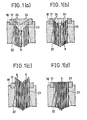
- needles 9 among components which are formed into a unit as a magnet block are inserted into a tapered hole 22 from a rear end of a guide holder 18 and are aligned into a row by a guide hole 23 in the form of a slit formed in contiguous relationship to the tapered hole 22.
- the needles 9 are formed to have a greater length toward outside so that the outermost needles are greater in length than the central needles.
- the needles 9 which have rear ends disposed thus along a parabola or arcuate line are guided outwardly so that they are inserted into needle holes 24 in a needle guide 17 in order beginning with the outermost needles
- Fig. l(b) While the outermost needles 9 are guided by opposite ends of the guide hole 23 in the form of a slit, inner ones of the needles 9 are guided by guide faces provided by inner faces of outer needles 9 adjacent thereto and are introduced into the chamfered needle holes 24. If all the needles 9 are inserted into the needle guide 17 as shown in Fig. l(c), they will have different extensions from the needle guide 17. Therefore, after a guide holder 18 is secured to the magnet block, the needles 19 are polished to a plane coplanar with a front face of the needle guide 17 as illustrated in Fig. l(d).
- a cover 1, a PC plate 2, a case 3 and a yoke 4 are put one on another, and a plurality of screws 5, which will act also as guide poles after assembly, are passed through them and a plurality of guide poles 6 are erected on the yoke 4.
- a plurality of cores 7 are disposed radially around an outer periphery of the yoke 4, and coils 8 are mounted on the cores 7.
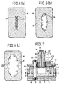
- a guide holder 18 made of a synthetic resin material to which a needle guide 17 is secured has formed therein mounting holes 19 for passing the screws 5 therethrough, a mounting hole 20 for assembling to a carrier, a rear opening 21 having a large area, a tapered hole 22 having a sectional area which decreases from an end thereof adjacent or is tapered toward the rear opening 21, and a guide hole 23 in the form of a slit.
- the needle guide 17 has a plurality of needle holes 24 formed therein so as to allow the needles 9 to be arranged in a predetermined pitch in a row without interference thereamong.
- the needle holes 24 are formed in partly contiguous relationship as seen in Fig. 3 and are worked with chamfering 25 at opposite ends thereof as seen in Fig. 4.
- the guide hole 23 has a length and width sufficient to oppose to all the needle holes 24.
- the needles 9 are open so that the ends thereof are positioned as shown in full lines in Fig. 5. Then, in order to assemble the magnet block 16 and the guide holder 18, the needles 9 are inserted into the tapered hole 22 from the opening 21 at the rear end of the guide holder 18 as shown in Fig. 1(a). The needles 9 are directed inwardly by the inner periphery of the tapered hole 22 which become thinner toward the end thereof until they are aligned in a row by the guide hole 23 in the form of a slit as shown in Figs. l(a) and 6. As seen from Fig.
- the needles 9 are differentiated in length from each other such that the length is greatest at the needles 9 which are to be inserted into the opposite end needles holes 24 and decreases towards the innermost needles 9, as the needles 9 are inserted further deeply into the guide hole 23, the outermost needles 9 will be guided by the opposite end edges of the guide hole 23 and inserted into the opposite outermost needle holes 24. Since the needles 9 are forcibly aligned into a row from the open position thereof, the inner needles 9 are deflected inwardly by the outer needles 9 in the guide hole 23 and only central needles 9 are in an unstable condition.
- the inner needles 9 are each guided by a guide face provided by an inside face of an outer adjacent needle 9 thereto and are inserted into the respective needle holes 24 while the central needle 9 is inserted into the central needle hole 24 under the guidance of a guide face provided by a side face of either one of opposite needles 9 adjacent thereto, as seen in Fig. l(b).
- the needles9 are dislocated a greater distance from the corresponding needle holes 24 toward the center one, they are not inserted into the needle holes 24 at once but are inserted into and corrected in position by the respective needle holes 24 one after another beginning with the outermost ones. Accordingly, not only the outermost ones but also the central one of the needles 9 are inserted in the same condition. Slight dislocation of the needles 9 just before insertion could be corrected by the chamfered faces 25.
- the dot printer head which has been assembled in this manner will be installed onto a printer, and such printing operation will be described briefly. If a particular one or ones of the coils 8 are energized, the corresponding armatures 10 are pivoted around fulcra provided by contact points thereof with the yoke 4 and are attracted to the corresponding cores 7, thereby causing the corresponding needles 9 to impact upon a platen.
- needles 9 having a same length in each pair are arranged.
- the needles 9 are guided by each pair beginning with the outermost pair, and the inner pairs of the needles 9 are guided in a similar manner to that described above so that the needles 9 will be smoothly inserted into the needle holes 24 at last.
Landscapes
- Impact Printers (AREA)
Applications Claiming Priority (2)
| Application Number | Priority Date | Filing Date | Title |
|---|---|---|---|
| JP59192040A JPS6168255A (ja) | 1984-09-13 | 1984-09-13 | ドツトプリンタヘツドの製造方法 |
| JP192040/84 | 1984-09-13 |
Publications (3)
| Publication Number | Publication Date |
|---|---|
| EP0174829A2 true EP0174829A2 (de) | 1986-03-19 |
| EP0174829A3 EP0174829A3 (en) | 1987-04-22 |
| EP0174829B1 EP0174829B1 (de) | 1990-05-09 |
Family
ID=16284603
Family Applications (1)
| Application Number | Title | Priority Date | Filing Date |
|---|---|---|---|
| EP85306412A Expired - Lifetime EP0174829B1 (de) | 1984-09-13 | 1985-09-10 | Herstellungsverfahren eines Nadeldruckkopfes |
Country Status (5)
| Country | Link |
|---|---|
| US (1) | US4611393A (de) |
| EP (1) | EP0174829B1 (de) |
| JP (1) | JPS6168255A (de) |
| KR (1) | KR910000431B1 (de) |
| DE (1) | DE3577527D1 (de) |
Cited By (3)
| Publication number | Priority date | Publication date | Assignee | Title |
|---|---|---|---|---|
| US4950092A (en) * | 1987-11-10 | 1990-08-21 | Oki Electric Industry Co., Ltd. | Wire dot print head with a pair of guide nose halves |
| EP0409536A3 (en) * | 1989-07-17 | 1991-04-24 | Ing. C. Olivetti & C., S.P.A. | Wire printing head for a high resolution printer |
| US7201700B2 (en) | 2003-05-03 | 2007-04-10 | Goodrich Actuation Systems Ltd. | Geared rotary actuators |
Families Citing this family (6)
| Publication number | Priority date | Publication date | Assignee | Title |
|---|---|---|---|---|
| US5236266A (en) * | 1985-01-25 | 1993-08-17 | Seiko Epson Corporation | Stacked print wire driving device for wire type dot printer |
| JPH051405Y2 (de) * | 1986-05-30 | 1993-01-14 | ||
| EP0312319A3 (de) * | 1987-10-15 | 1989-09-06 | Tokyo Electric Co., Ltd. | Nach dem Auslöseprinzip arbeitender Punktdruckkopf und Verfahren zu seiner Herstellung |
| EP0341930A3 (de) * | 1988-05-10 | 1990-01-10 | Tokyo Electric Co., Ltd. | Nach dem Auslöseprinzip arbeitender Punktdruckkopf |
| DE68913933T2 (de) * | 1988-12-19 | 1994-07-21 | Seiko Epson Corp | Punktnadelanschlagdrucker. |
| US5126186A (en) * | 1991-06-24 | 1992-06-30 | Cheek Maurice R | Enhancement of fabric ribbon type impressions |
Family Cites Families (4)
| Publication number | Priority date | Publication date | Assignee | Title |
|---|---|---|---|---|
| US3897865A (en) * | 1973-12-11 | 1975-08-05 | Ibm | Dot printing apparatus |
| US4185929A (en) * | 1978-03-10 | 1980-01-29 | Helmut Falk | Wire matrix print head assembly |
| JPS5637176A (en) * | 1979-09-03 | 1981-04-10 | Oki Electric Ind Co Ltd | Printing head for dot printer |
| US4501506A (en) * | 1983-02-25 | 1985-02-26 | Ncr Corporation | Dot matrix print head |
-
1984
- 1984-09-13 JP JP59192040A patent/JPS6168255A/ja active Granted
-
1985
- 1985-09-10 DE DE8585306412T patent/DE3577527D1/de not_active Expired - Lifetime
- 1985-09-10 EP EP85306412A patent/EP0174829B1/de not_active Expired - Lifetime
- 1985-09-11 KR KR1019850006643A patent/KR910000431B1/ko not_active Expired
- 1985-09-12 US US06/775,395 patent/US4611393A/en not_active Expired - Fee Related
Cited By (3)
| Publication number | Priority date | Publication date | Assignee | Title |
|---|---|---|---|---|
| US4950092A (en) * | 1987-11-10 | 1990-08-21 | Oki Electric Industry Co., Ltd. | Wire dot print head with a pair of guide nose halves |
| EP0409536A3 (en) * | 1989-07-17 | 1991-04-24 | Ing. C. Olivetti & C., S.P.A. | Wire printing head for a high resolution printer |
| US7201700B2 (en) | 2003-05-03 | 2007-04-10 | Goodrich Actuation Systems Ltd. | Geared rotary actuators |
Also Published As
| Publication number | Publication date |
|---|---|
| EP0174829A3 (en) | 1987-04-22 |
| KR860002370A (ko) | 1986-04-24 |
| KR910000431B1 (ko) | 1991-01-25 |
| EP0174829B1 (de) | 1990-05-09 |
| JPS6168255A (ja) | 1986-04-08 |
| JPH0255231B2 (de) | 1990-11-26 |
| DE3577527D1 (de) | 1990-06-13 |
| US4611393A (en) | 1986-09-16 |
Similar Documents
| Publication | Publication Date | Title |
|---|---|---|
| US4611393A (en) | Process for producing a dot printer head | |
| US4525085A (en) | Serial printer | |
| US4165940A (en) | Free flight head assembly for dot matrix printers and the like | |
| EP0083401A2 (de) | Druckkopf mit Nadelmatrix | |
| US4180333A (en) | Bearing for the printing head of a matrix printer, and printing head comprising such a bearing | |
| US4279518A (en) | Dot matrix print head | |
| EP0137820B1 (de) | Matrix-nadeldruckkopf und dessen montageverfahren | |
| US4647237A (en) | Dot matrix print head | |
| CA1163137A (en) | Stylus printing head comprising electromagnets on resilient supports | |
| US4674179A (en) | Making an armature assembly for matrix print heads | |
| US4662764A (en) | Ruby and needle guiding group for needle printing head | |
| JPH0414070B2 (de) | ||
| EP0167228A2 (de) | Zusammenbau von Punktmatrixdruckköpfen | |
| US4950092A (en) | Wire dot print head with a pair of guide nose halves | |
| US4682903A (en) | Thin line printer typing head | |
| US4749290A (en) | Core structure for electromagnetic print head | |
| EP0530853B1 (de) | Punktmatrixdrucker mit Anschlagdruckkopf | |
| CS214194B1 (cs) | Mozaiková tiskací hlavička | |
| US5215389A (en) | Print head for a dot matrix printer | |
| JPS6058871A (ja) | ドットプリンタ−の印字ヘッド | |
| JPS592858A (ja) | ワイヤピンの位置決め方法 | |
| KR850007134A (ko) | 프린터용 도트 매트릭스 헤드(2) | |
| JPH03108560A (ja) | インパクトドットヘッド | |
| JPS5637175A (en) | Printing head for dot printer | |
| JPS57170765A (en) | Assembling of print head |
Legal Events
| Date | Code | Title | Description |
|---|---|---|---|
| PUAI | Public reference made under article 153(3) epc to a published international application that has entered the european phase |
Free format text: ORIGINAL CODE: 0009012 |
|
| AK | Designated contracting states |
Kind code of ref document: A2 Designated state(s): DE FR GB |
|
| PUAL | Search report despatched |
Free format text: ORIGINAL CODE: 0009013 |
|
| AK | Designated contracting states |
Kind code of ref document: A3 Designated state(s): DE FR GB |
|
| 17P | Request for examination filed |
Effective date: 19870922 |
|
| 17Q | First examination report despatched |
Effective date: 19890111 |
|
| GRAA | (expected) grant |
Free format text: ORIGINAL CODE: 0009210 |
|
| RAP1 | Party data changed (applicant data changed or rights of an application transferred) |
Owner name: TOKYO ELECTRIC CO., LTD. |
|
| AK | Designated contracting states |
Kind code of ref document: B1 Designated state(s): DE FR GB |
|
| REF | Corresponds to: |
Ref document number: 3577527 Country of ref document: DE Date of ref document: 19900613 |
|
| ET | Fr: translation filed | ||
| PLBE | No opposition filed within time limit |
Free format text: ORIGINAL CODE: 0009261 |
|
| STAA | Information on the status of an ep patent application or granted ep patent |
Free format text: STATUS: NO OPPOSITION FILED WITHIN TIME LIMIT |
|
| 26N | No opposition filed | ||
| PGFP | Annual fee paid to national office [announced via postgrant information from national office to epo] |
Ref country code: FR Payment date: 19930830 Year of fee payment: 9 |
|
| PGFP | Annual fee paid to national office [announced via postgrant information from national office to epo] |
Ref country code: GB Payment date: 19930831 Year of fee payment: 9 |
|
| PGFP | Annual fee paid to national office [announced via postgrant information from national office to epo] |
Ref country code: DE Payment date: 19931029 Year of fee payment: 9 |
|
| PG25 | Lapsed in a contracting state [announced via postgrant information from national office to epo] |
Ref country code: GB Effective date: 19940910 |
|
| GBPC | Gb: european patent ceased through non-payment of renewal fee |
Effective date: 19940910 |
|
| PG25 | Lapsed in a contracting state [announced via postgrant information from national office to epo] |
Ref country code: FR Effective date: 19950531 |
|
| PG25 | Lapsed in a contracting state [announced via postgrant information from national office to epo] |
Ref country code: DE Effective date: 19950601 |
|
| REG | Reference to a national code |
Ref country code: FR Ref legal event code: ST |