EP0175208B1 - Verfahren und Vorrichtung zum Sammeln von Waren - Google Patents
Verfahren und Vorrichtung zum Sammeln von Waren Download PDFInfo
- Publication number
- EP0175208B1 EP0175208B1 EP85111121A EP85111121A EP0175208B1 EP 0175208 B1 EP0175208 B1 EP 0175208B1 EP 85111121 A EP85111121 A EP 85111121A EP 85111121 A EP85111121 A EP 85111121A EP 0175208 B1 EP0175208 B1 EP 0175208B1
- Authority
- EP
- European Patent Office
- Prior art keywords
- commodities
- pusher
- length
- commodity
- row
- Prior art date
- Legal status (The legal status is an assumption and is not a legal conclusion. Google has not performed a legal analysis and makes no representation as to the accuracy of the status listed.)
- Expired
Links
- 238000000034 method Methods 0.000 title claims description 14
- 238000012856 packing Methods 0.000 description 2
- 235000011389 fruit/vegetable juice Nutrition 0.000 description 1
- 235000013336 milk Nutrition 0.000 description 1
- 239000008267 milk Substances 0.000 description 1
- 210000004080 milk Anatomy 0.000 description 1
- 238000009751 slip forming Methods 0.000 description 1
Images

Classifications
-
- B—PERFORMING OPERATIONS; TRANSPORTING
- B65—CONVEYING; PACKING; STORING; HANDLING THIN OR FILAMENTARY MATERIAL
- B65G—TRANSPORT OR STORAGE DEVICES, e.g. CONVEYORS FOR LOADING OR TIPPING, SHOP CONVEYOR SYSTEMS OR PNEUMATIC TUBE CONVEYORS
- B65G47/00—Article or material-handling devices associated with conveyors; Methods employing such devices
- B65G47/02—Devices for feeding articles or materials to conveyors
- B65G47/04—Devices for feeding articles or materials to conveyors for feeding articles
- B65G47/06—Devices for feeding articles or materials to conveyors for feeding articles from a single group of articles arranged in orderly pattern, e.g. workpieces in magazines
- B65G47/08—Devices for feeding articles or materials to conveyors for feeding articles from a single group of articles arranged in orderly pattern, e.g. workpieces in magazines spacing or grouping the articles during feeding
-
- B—PERFORMING OPERATIONS; TRANSPORTING
- B65—CONVEYING; PACKING; STORING; HANDLING THIN OR FILAMENTARY MATERIAL
- B65G—TRANSPORT OR STORAGE DEVICES, e.g. CONVEYORS FOR LOADING OR TIPPING, SHOP CONVEYOR SYSTEMS OR PNEUMATIC TUBE CONVEYORS
- B65G47/00—Article or material-handling devices associated with conveyors; Methods employing such devices
- B65G47/02—Devices for feeding articles or materials to conveyors
- B65G47/04—Devices for feeding articles or materials to conveyors for feeding articles
- B65G47/06—Devices for feeding articles or materials to conveyors for feeding articles from a single group of articles arranged in orderly pattern, e.g. workpieces in magazines
- B65G47/08—Devices for feeding articles or materials to conveyors for feeding articles from a single group of articles arranged in orderly pattern, e.g. workpieces in magazines spacing or grouping the articles during feeding
- B65G47/084—Devices for feeding articles or materials to conveyors for feeding articles from a single group of articles arranged in orderly pattern, e.g. workpieces in magazines spacing or grouping the articles during feeding grouping articles in a predetermined 2-dimensional pattern
- B65G47/086—Devices for feeding articles or materials to conveyors for feeding articles from a single group of articles arranged in orderly pattern, e.g. workpieces in magazines spacing or grouping the articles during feeding grouping articles in a predetermined 2-dimensional pattern cubiform articles
-
- B—PERFORMING OPERATIONS; TRANSPORTING
- B65—CONVEYING; PACKING; STORING; HANDLING THIN OR FILAMENTARY MATERIAL
- B65B—MACHINES, APPARATUS OR DEVICES FOR, OR METHODS OF, PACKAGING ARTICLES OR MATERIALS; UNPACKING
- B65B35/00—Supplying, feeding, arranging or orientating articles to be packaged
- B65B35/30—Arranging and feeding articles in groups
- B65B35/40—Arranging and feeding articles in groups by reciprocating or oscillatory pushers
Definitions
- the present invention relates to a method and a device for collecting a plurality of square or rectangular commodities such as square or rectangular cylindrical paper containers for milk and juice into a group.
- a previously employed method consists in that the commodities conveyed by a conveyor are individually pushed out sideways by a pusher.
- this method is inefficient because only one commodity is handled by one operation of the pusher.
- it is sometimes desired to change the packing pattern so that, for example, five commodities may form one set or two rows respectively including five may be formed.
- the prior art method can not fully satisfy this requirement.
- the present invention provides a method and a device in which a plurality of square commodities are collected into one group by utilizing a pusher and in which the aforementioned difficulty is prevented.
- the method is characterized in that the commodity group is pushed out in such a condition that the mutually contacting surfaces of the longitudinally adjacent commodities in each row are shifted forwardly or rearwardly with respect to the contact surfaces of the longitudinally adjacent commodities in the adjacent row.
- the device is characterized by a stepwise tapered pusher on which steps having a longitudinal length shorter than the length of a commodity and a substantially same lateral length as the width of the square commodity are continuously formed, said pusher being disposed on an operation table provided at a side of a conveyor for conveying the commodities and being slidable in a longitudinal direction parallel to the conveyor.
- the pusher is tapered and is provided with the continuous steps having enough size to accommodate the commodities, and the commodities are pushed out by the pusher in a configuration such that the contact surfaces of the longitudinally adjacent commodities in any one row are shifted forwardly or rearwardly with respect to the contact surfaces of the longitudinally adjacent commodities in the adjacent row.
- the corners of the commodities in adjacent rows have been necessarily shifted forwardly or rearwardly to each other, so that the side surfaces of the commodities in the row function as a sort of guide for corners of the commodities of the adjacent row which is being pushed out by the pusher.
- any forward stroke of the pusher by a stroke length corresponding to the length of one commodity will have the effect that the commodities in adjacent rows are forwardly or rearwardly shifted and are pushed out in this shifted condition.
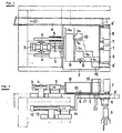
- Figure 1 is a plan view illustrating a whole collecting device for commodities according to a
- A indicates a conveyor for conveying the commodities, which is always driven in a direction of the arrow.
- a stopper 1 is provided at the forward end of the conveyor A, so that the commodities successively delivered are stopped there.
- a flat operation table 2 is provided at one side of the conveyor A.
- a pusher B driven by a cylinder 3 to slide parallel to the conveyor A is provided on the operation table 2.
- the pusher B is, as illustrated in Figure 3 in detail, of stepwise tapered shape and is provided with continuous recesses or steps b1-b6 each of which has a smaller longitudinal size than a length L of the square or rectangular commodity P to be handled and has substantially the same lateral size as the width W of the commodity P.
- the steps b1, b2 and b3 have longitudinal lengths which are shorter by length L1 than the length L of the commodities P to be handled.
- the steps b4 and b5 are still shorter and have a longitudinal length equal to the length L1, respectively.
- the width of the steps b2-b6 are same as the widths of the commodities P respectively, the width of the step b1 is shorter by a length L2 than the width W of the commodity P.
- the pusher B is provided with two laterally spaced rods 4 and 4 extending rearwardly. Both rods 4 and 4 are adapted to slide in guide tubes 5 and 5 provided at the left and right sides of a cylinder 3, when the pusher b is operated by the cylinder 3. Further, rollers 6 adapted to roll on the operation table 2 are disposed under the lower surface of the pusher B. The rods 4 inserted into the tubes 5 and the rollers 6 under the pusher B enable the relatively large pusher B to slide smoothly without tieting.
- Permanent stoppers 7 are disposed at the middle portion of the forward end of the o p er- ation table 2, i.e., in front of the steps b3 and b4 of the pusher B. Outwardly spaced from the two stoppers 7 are disposed two storage platforms 8 which are adapted to move vertically between a position at a same level as the operation table 2 and a position lower than that. The vertical movements of the left and right storage platforms 8 are performed by two individually disposed vertical cylinders 9. Vertical guide plates 8' are disposed at the outersides of the two storage platforms 8.
- a stopper 10 is fixed at a position shown in Figure 1 on the upper surface of the operation table 2. However, the height of the stopper 10 is so determined that the bottom of the pusher B may pass thereover without being impeded by the stopper 10.
- pushers 11 which are operable to longitudinally move between the operation table 2 and the storage platforms 8 at the lowermost position are disposed and associated to the storage platforms 8, respectively.
- the right and left pushers 11 are adapted to be longitudinally (horizontally in Figure 2) moved by the cylinders 12 and 12 individually arranged at the left and the right.
- the pistons of the cylinders 12 are operable to be moved from a position shown by a solid line in Figure 2 to a position shown by the broken line.
- Each pusher 11 is, similarly to the pusher B, also provided with two left and right rods 13 which extend rearwardly and are adapted to slide in guide tubes 14 disposed at the left and the right of each cylinder 12 when the pusher 11 operates.
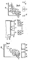
- the numeral 15 in Figures 1, 2 and 4a-d indicates a stopper disposed at the side of the pusher B on the operation table 2 and downstream of the guide plate 8'.
- the pusher 15 is so arranged that the inside surface thereof may be positioned on substantially the same line as the outside surface of the pusher B (in the strict sense, slightly offset from the outside surface of the pusher B).
- the device divides and collects the commodities into two groups each including laterally aligned two commodities with the two groups being separated by a space corresponding to two commodities.
- one commodity is preset in front of the second step b2 of the pusher, two are preset respectively in front of the third to fifth steps b3-b5, and three are preset in front of the last step b6.
- the totally ten commodities are preset at appropriate positions except for the positions just in front of the steps bl-b6, and the end surfaces of the commodities at the left and may register with the left end surface of the pusher B. In this case, the commodities are not placed on the portions just in front of the stages b1 ⁇ b6 to keep them vacant.
- the commodities which are arranged at the portions in front of the stages b1-b6 with spaces respectively corresponding to one commodity are disposed in such a condition that the longitudinally contact surfaces thereof are shifted respectively by the length L1 with respect to the longitudinally contact surfaces of the commodities at the adjacent row.
- the contact surfaces of the commodities in each longitudinal row are not laterally aligned with the contact surfaces of the commodities at the adjacent row, but are positioned beside the side surfaces of the commodities at the adjacent row.
- the conveyor A is driven to convey the commodities at random.
- the commodity P1 at the forefront is intercepted by the stopper 1 provided at the end of the conveyor A, so that the succeeding three commodities P2-P4 are stopped to be adjacent to the rear of the commodity P1 at the side of the operation table 2.
- the commodities P1 ⁇ P4 are pushed, as shown in Figure 4b, into the pusher B by a further pusher or the like (not shown), provided at the other side of the conveyor A and movable across conveyor A.
- a further pusher or the like not shown
- the commodity P4 at the rear end is accommodated in the rear end step b6 and the commodities P3-P1 are longitudinally aligned in one row at the front thereof.
- the commodities which have been set in front of the pusher B are transversely or laterally moved one by one, so that the commodity at the right end in the first transverse row is accommodated in the forefront step b1 of the pusher B and the commodity at the right end in the second transverse row is accommodated in the second step b2.
- the commodities are respectively accommodated in the vacant portions of the steps.
- the commodity pushed into the forfront step b1 is intercepted by the stopper 15, so that it is not transversely moved further and is stopped at the position just in front of the step b1.
- the commodities P1-P3 among the newly added commodities P1-P4 are positioned just beside the commodities at the adjacent row which have been transversely moved to the position in front of the stage b5. In this position, the contact surfaces of longitudinally adjacent commodities in these two adjacent rows temporarily coincide with each other.
- the collecting operation can be performed without the risk that the corners of the commodities catch the adjacent commodities so that the commodities may be deformed or the rows become disordered.
- the pusher B is so designed that the commodities in front of the steps after the first step are not closely fitted to the steps but transversely shifted by the length L2 in Figure 3. According to this structure the risk can also be avoided that the corners of the steps of the pusher B catch the commodities.
- the cylinder 9 lowers the two storage platforms 8 to a position shown by broken line in Figure 5. Then, the cylinder 12 forwards the pusher 11 situated under the operation table 2 to a position shown by the solid line in Figure 6, so that the two commodities are pushed out from each storage platform 8.
- This operation is repeated to collect the two commodities two by two into groups divided and spaced with the two stoppers 7 therebetween.
- the collecting number or the space (C in Figure 7) between the groups can easily be changed by appropriately changing the number of the steps of the pusher B, the number of the commodities pushed into it and the space between the stoppers 7 and the guide plates 8'.
- FIG 8 illustrates another embodiment of the pusher, which is different from the pusher shown in Figure 1 by being provided with contiguous steps having same longitudinal and transverse sizes except for the first step b1 which has a width smaller by L2 than those of the others.
- Each longitudinal length of the second to sixth stages b2-b6 is same as those of the second and third stages b2 and b3 of the pusher shown in Figure 1 and is shorter by L2 than the length L of the commodity.
- Each width of the stages b2-b6 is same as those of the second and third stages b2 and b3 of the pusher shown in Figure 1 and is same as the width of the commodity P.
- the foremost step has a width which is smaller by L2 than the width W of the commodity P similarly to the pusher shown in Figure 1.
- the device can be so modified that the pusher B shown in Figure 1 is replaced by the pusher B' shown in Figure 8, the stoppers 7 are eliminated and the operation table 2 is enlarged so as to enable up to longitudinally six commodities to be accommodated in front of the step b6 of the pusher B'.
- the commodities can be collected into groups of six on the storage platforms 8, and on a further platform (indicated at 16 in Figure 8) therebetween.
- the method of the invention groups of commodities forming longitudinal rows of abutting commodities are loaded set by set into the tapered pusher on which steps having enough size to accommodate the square commodities are contiguously formed, and the pusher is forwarded by a length corresponding to one commodity in operation cycle. This avoids the risk that one or more commodities among the commodities in front of the pusher are deformed or the rows are disordered. Therefore, the collecting operation is improved. Further, according to the device of the invention, the collecting operation for the commodities can be performed automatically and efficiently.
Landscapes
- Engineering & Computer Science (AREA)
- Mechanical Engineering (AREA)
- Attitude Control For Articles On Conveyors (AREA)
- Special Conveying (AREA)
- Stacking Of Articles And Auxiliary Devices (AREA)
Claims (5)
Applications Claiming Priority (2)
| Application Number | Priority Date | Filing Date | Title |
|---|---|---|---|
| JP185265/84 | 1984-09-03 | ||
| JP59185265A JPS6164625A (ja) | 1984-09-03 | 1984-09-03 | 物品の集積方法及びその装置 |
Publications (2)
| Publication Number | Publication Date |
|---|---|
| EP0175208A1 EP0175208A1 (de) | 1986-03-26 |
| EP0175208B1 true EP0175208B1 (de) | 1988-07-13 |
Family
ID=16167798
Family Applications (1)
| Application Number | Title | Priority Date | Filing Date |
|---|---|---|---|
| EP85111121A Expired EP0175208B1 (de) | 1984-09-03 | 1985-09-03 | Verfahren und Vorrichtung zum Sammeln von Waren |
Country Status (5)
| Country | Link |
|---|---|
| US (1) | US4744457A (de) |
| EP (1) | EP0175208B1 (de) |
| JP (1) | JPS6164625A (de) |
| KR (1) | KR920009296B1 (de) |
| DE (1) | DE3563728D1 (de) |
Families Citing this family (5)
| Publication number | Priority date | Publication date | Assignee | Title |
|---|---|---|---|---|
| DE102012106111A1 (de) | 2012-07-06 | 2014-01-09 | Dematic Gmbh | Vorrichtung zum mehrlagigen Bestapeln einer Unterlage |
| DE102012106112A1 (de) | 2012-07-06 | 2014-01-09 | Dematic Gmbh | Vorrichtung und Verfahren zum mehrlagigen Bestapeln einer Unterlage |
| DE102012106113A1 (de) | 2012-07-06 | 2014-01-09 | Dematic Gmbh | Vorrichtung zum mehrlagigen Bestapeln einer Unterlage |
| DE102012106109A1 (de) * | 2012-07-06 | 2014-01-09 | Dematic Gmbh | Vorrichtung zum mehrlagigen Bestapeln einer Unterlage |
| US11180327B2 (en) | 2017-03-29 | 2021-11-23 | Dematic Gmbh | Method for automatically stacking packages in layers on a support |
Family Cites Families (9)
| Publication number | Priority date | Publication date | Assignee | Title |
|---|---|---|---|---|
| US2090129A (en) * | 1933-09-02 | 1937-08-17 | Standard Knapp Corp | Package collector |
| GB461546A (en) * | 1936-09-28 | 1937-02-18 | Siefvert & Fornander Ab | Improvements in and relating to the arrangement of boxes and like articles for insertion into shells, and other like purposes |
| US3068624A (en) * | 1960-02-02 | 1962-12-18 | Int Paper Co | Method and apparatus for packing articles in flexible cases |
| US3923144A (en) * | 1974-03-18 | 1975-12-02 | Langen H J & Sons Ltd | Intermittent load accumulator |
| JPS5245277A (en) * | 1975-10-08 | 1977-04-09 | Hitachi Ltd | Method for production of complementary mis-ic |
| SE408702B (sv) * | 1977-10-26 | 1979-07-02 | Gustavsberg Ab | Aggregat for stapling av brent tegel pa lastpallar |
| JPS5843288B2 (ja) * | 1980-11-07 | 1983-09-26 | 大阪機工株式会社 | 物品の整列収納装置 |
| JPS60178125A (ja) * | 1984-02-25 | 1985-09-12 | テトラ パック インターナショナル アクテイエボラーグ | 物品集積方法及びその装置 |
| JPS6118637A (ja) * | 1984-06-29 | 1986-01-27 | エービー テトラパック | 物品の分離集積方法及びその装置 |
-
1984
- 1984-09-03 JP JP59185265A patent/JPS6164625A/ja not_active Withdrawn
-
1985
- 1985-09-02 KR KR1019850006389A patent/KR920009296B1/ko not_active Expired
- 1985-09-03 DE DE8585111121T patent/DE3563728D1/de not_active Expired
- 1985-09-03 EP EP85111121A patent/EP0175208B1/de not_active Expired
-
1987
- 1987-05-04 US US07/048,970 patent/US4744457A/en not_active Expired - Lifetime
Also Published As
| Publication number | Publication date |
|---|---|
| KR920009296B1 (ko) | 1992-10-15 |
| DE3563728D1 (en) | 1988-08-18 |
| US4744457A (en) | 1988-05-17 |
| JPS6164625A (ja) | 1986-04-03 |
| EP0175208A1 (de) | 1986-03-26 |
| KR860002409A (ko) | 1986-04-24 |
Similar Documents
| Publication | Publication Date | Title |
|---|---|---|
| US4610347A (en) | Dividing device for collecting commodities incorporated in a commodity collecting device | |
| US6945380B2 (en) | Intermediate storage device and process for transporting objects | |
| EP0396960B1 (de) | Verfahren und Anlage zum Umordnen von sortenweise palettierten Gegenständen zu Gruppen bestimmter Sortenzusammenstellung | |
| US3876057A (en) | Method and apparatus for arranging bricks to be fed in a predetermined number of rows | |
| US4911281A (en) | System for sorting a subdivided plate workpiece | |
| US6834755B2 (en) | Conveying machines | |
| WO1997042113A1 (en) | Container sweep for a palletizer | |
| US3887060A (en) | Apparatus and methods for forming rows of selectively spaced articles | |
| NL9300007A (nl) | Drie-dimensioneel opstapelsysteem voor blokken vellen. | |
| EP0166459B1 (de) | Verfahren und Vorrichtung zum Zusammenstellen von hintereinander herangeförderten Gegenständen in wenigstens zwei beabstandeten Gruppen | |
| US5450941A (en) | Apparatus for separating, conveying and grouping flat items | |
| US5761882A (en) | Method and apparatus for inserting flat partition elements between flanked articles | |
| US6152681A (en) | Container sweep for a palletizer and method | |
| EP0811327A1 (de) | Verfahren und Vorrichtung zur Handhabung von Zigarettenschragen | |
| EP0175208A1 (de) | Verfahren und Vorrichtung zum Sammeln von Waren | |
| DE19630554C2 (de) | Beschickungsvorrichtung zum Beschicken einer Verpackungsposition mit einer Produkteinheit | |
| EP0717700B1 (de) | Verfahren und vorrichtung zum zuführen von trennwänden in gruppen von gegenständen | |
| US12187476B2 (en) | Packing machine for horizontal and vertical packing of articles into a packing box | |
| KR890005327B1 (ko) | 물품집적장치 | |
| EP0778205B1 (de) | Verfahren und Vorrichtung zum Bilden einer zweilagigen Reihenformation aus zweibahnig zugeführten Packungen der tabakverarbeitenden Industrie | |
| EP4393853A1 (de) | Vorrichtung zur übergabe von einzelnen fördergütern an eine weiterfördervorrichtung sowie ein fördersystem und ein übergabeverfahren | |
| US2686543A (en) | Conveyer system | |
| GB2107690A (en) | Palletising equipment and process | |
| GB2116508A (en) | A method and an apparatus for forming several stacks which lie side by side | |
| GB2119335A (en) | Device for separating articles |
Legal Events
| Date | Code | Title | Description |
|---|---|---|---|
| PUAI | Public reference made under article 153(3) epc to a published international application that has entered the european phase |
Free format text: ORIGINAL CODE: 0009012 |
|
| AK | Designated contracting states |
Kind code of ref document: A1 Designated state(s): BE CH DE FR GB IT LI NL SE |
|
| 17P | Request for examination filed |
Effective date: 19860714 |
|
| 17Q | First examination report despatched |
Effective date: 19870209 |
|
| RAP1 | Party data changed (applicant data changed or rights of an application transferred) |
Owner name: AB TETRA PAK |
|
| GRAA | (expected) grant |
Free format text: ORIGINAL CODE: 0009210 |
|
| AK | Designated contracting states |
Kind code of ref document: B1 Designated state(s): BE CH DE FR GB IT LI NL SE |
|
| REF | Corresponds to: |
Ref document number: 3563728 Country of ref document: DE Date of ref document: 19880818 |
|
| ET | Fr: translation filed | ||
| ITF | It: translation for a ep patent filed | ||
| PLBE | No opposition filed within time limit |
Free format text: ORIGINAL CODE: 0009261 |
|
| STAA | Information on the status of an ep patent application or granted ep patent |
Free format text: STATUS: NO OPPOSITION FILED WITHIN TIME LIMIT |
|
| 26N | No opposition filed | ||
| ITTA | It: last paid annual fee | ||
| EAL | Se: european patent in force in sweden |
Ref document number: 85111121.1 |
|
| PGFP | Annual fee paid to national office [announced via postgrant information from national office to epo] |
Ref country code: FR Payment date: 19980820 Year of fee payment: 14 |
|
| PGFP | Annual fee paid to national office [announced via postgrant information from national office to epo] |
Ref country code: NL Payment date: 19980825 Year of fee payment: 14 |
|
| PGFP | Annual fee paid to national office [announced via postgrant information from national office to epo] |
Ref country code: GB Payment date: 19980826 Year of fee payment: 14 |
|
| PGFP | Annual fee paid to national office [announced via postgrant information from national office to epo] |
Ref country code: BE Payment date: 19980914 Year of fee payment: 14 |
|
| PGFP | Annual fee paid to national office [announced via postgrant information from national office to epo] |
Ref country code: CH Payment date: 19981005 Year of fee payment: 14 |
|
| PG25 | Lapsed in a contracting state [announced via postgrant information from national office to epo] |
Ref country code: GB Free format text: LAPSE BECAUSE OF NON-PAYMENT OF DUE FEES Effective date: 19990903 |
|
| PG25 | Lapsed in a contracting state [announced via postgrant information from national office to epo] |
Ref country code: LI Free format text: LAPSE BECAUSE OF NON-PAYMENT OF DUE FEES Effective date: 19990930 Ref country code: CH Free format text: LAPSE BECAUSE OF NON-PAYMENT OF DUE FEES Effective date: 19990930 Ref country code: BE Free format text: LAPSE BECAUSE OF NON-PAYMENT OF DUE FEES Effective date: 19990930 |
|
| BERE | Be: lapsed |
Owner name: A.B. TETRA PAK Effective date: 19990930 |
|
| PG25 | Lapsed in a contracting state [announced via postgrant information from national office to epo] |
Ref country code: NL Free format text: LAPSE BECAUSE OF NON-PAYMENT OF DUE FEES Effective date: 20000401 |
|
| GBPC | Gb: european patent ceased through non-payment of renewal fee |
Effective date: 19990903 |
|
| REG | Reference to a national code |
Ref country code: CH Ref legal event code: PL |
|
| PG25 | Lapsed in a contracting state [announced via postgrant information from national office to epo] |
Ref country code: FR Free format text: LAPSE BECAUSE OF NON-PAYMENT OF DUE FEES Effective date: 20000531 |
|
| NLV4 | Nl: lapsed or anulled due to non-payment of the annual fee |
Effective date: 20000401 |
|
| REG | Reference to a national code |
Ref country code: FR Ref legal event code: ST |
|
| PGFP | Annual fee paid to national office [announced via postgrant information from national office to epo] |
Ref country code: SE Payment date: 20010820 Year of fee payment: 17 Ref country code: DE Payment date: 20010820 Year of fee payment: 17 |
|
| PG25 | Lapsed in a contracting state [announced via postgrant information from national office to epo] |
Ref country code: SE Free format text: LAPSE BECAUSE OF NON-PAYMENT OF DUE FEES Effective date: 20020904 |
|
| PG25 | Lapsed in a contracting state [announced via postgrant information from national office to epo] |
Ref country code: DE Free format text: LAPSE BECAUSE OF NON-PAYMENT OF DUE FEES Effective date: 20030401 |
|
| EUG | Se: european patent has lapsed |