EP0175231B1 - Récipient calorifugé - Google Patents
Récipient calorifugé Download PDFInfo
- Publication number
- EP0175231B1 EP0175231B1 EP85111266A EP85111266A EP0175231B1 EP 0175231 B1 EP0175231 B1 EP 0175231B1 EP 85111266 A EP85111266 A EP 85111266A EP 85111266 A EP85111266 A EP 85111266A EP 0175231 B1 EP0175231 B1 EP 0175231B1
- Authority
- EP
- European Patent Office
- Prior art keywords
- container
- heat
- insulated container
- collar
- edge
- Prior art date
- Legal status (The legal status is an assumption and is not a legal conclusion. Google has not performed a legal analysis and makes no representation as to the accuracy of the status listed.)
- Expired
Links
- 238000007789 sealing Methods 0.000 claims description 21
- 239000004033 plastic Substances 0.000 claims description 5
- 239000000463 material Substances 0.000 claims description 3
- 239000002984 plastic foam Substances 0.000 claims description 3
- 239000002245 particle Substances 0.000 claims description 2
- 230000013011 mating Effects 0.000 claims 4
- 230000036316 preload Effects 0.000 claims 3
- 238000012856 packing Methods 0.000 claims 2
- 230000003014 reinforcing effect Effects 0.000 claims 2
- 239000011521 glass Substances 0.000 description 17
- 238000010792 warming Methods 0.000 description 7
- 238000010276 construction Methods 0.000 description 3
- 230000005489 elastic deformation Effects 0.000 description 2
- 239000007788 liquid Substances 0.000 description 2
- 238000004519 manufacturing process Methods 0.000 description 2
- 230000006978 adaptation Effects 0.000 description 1
- 239000000853 adhesive Substances 0.000 description 1
- 230000001070 adhesive effect Effects 0.000 description 1
- 238000004140 cleaning Methods 0.000 description 1
- 238000011109 contamination Methods 0.000 description 1
- 230000001419 dependent effect Effects 0.000 description 1
- 230000000694 effects Effects 0.000 description 1
- 235000012171 hot beverage Nutrition 0.000 description 1
- 239000011810 insulating material Substances 0.000 description 1
- 238000009413 insulation Methods 0.000 description 1
- 230000007774 longterm Effects 0.000 description 1
- 239000002184 metal Substances 0.000 description 1
- 230000001681 protective effect Effects 0.000 description 1
- 230000000284 resting effect Effects 0.000 description 1
- 239000000565 sealant Substances 0.000 description 1
- 238000003860 storage Methods 0.000 description 1
Images
Classifications
-
- A—HUMAN NECESSITIES
- A47—FURNITURE; DOMESTIC ARTICLES OR APPLIANCES; COFFEE MILLS; SPICE MILLS; SUCTION CLEANERS IN GENERAL
- A47G—HOUSEHOLD OR TABLE EQUIPMENT
- A47G19/00—Table service
- A47G19/12—Vessels or pots for table use
- A47G19/127—Vessels or pots for table use with means for keeping liquid cool or hot
-
- A—HUMAN NECESSITIES
- A47—FURNITURE; DOMESTIC ARTICLES OR APPLIANCES; COFFEE MILLS; SPICE MILLS; SUCTION CLEANERS IN GENERAL
- A47G—HOUSEHOLD OR TABLE EQUIPMENT
- A47G19/00—Table service
- A47G19/12—Vessels or pots for table use
Definitions
- the invention relates to a warming can according to the preamble of claim 1.
- a warming can is known from DE-C-2 658 295.
- Such a warming jug is particularly suitable for the storage of hot drinks and consists of an inner container which holds the hot liquid and a heat-insulating jacket surrounding it.
- warming cans which consist of a glass inner container, an insulating layer surrounding it - for example made of plastic foam - and an outer jacket which is made of metal, for example (see e.g. DE-C-3 045 896).
- DE-A-2 952 557 shows a coffee pot which consists of a glass inner container and a surrounding, two-part, non-insulating protective jacket.
- the elastic prestressing of the inside edge of the collar produced by elastic deformation of the said collar edge ensures the required sealing. Due to the elastic deformability of the collar and its inner edge, dimensional deviations of the glass container of a few millimeters are easily absorbed both in the radial and in the axial direction. According to the invention, the security of the seal can be increased further in that the inner edge of the collar has a labyrinth of seals made of circumferential sealing lips.
- the glass container has an outwardly inclined upper edge region on which the inner edge of the collar of the plastic outer shell is supported in a sealing manner under radial and / or axial elastic prestress.
- the outer shell upper part is preferably designed in such a way that its lower edge overlaps the upper edge of the base part, the base part having a circumferential radial projection which, under radial pressure, lies around the inner surface of the upper part in a sealing manner.
- the radial press fit achieved in this way achieves a permanent, secure seal between the two outer shell parts, an approximately triangular cross-sectional shape with the tip pointing outwards having proven particularly useful for the circumferential radial projection.
- the upper and lower parts of the outer shell are preferably provided with interlocking fixing means, which are arranged on the inner wall of the upper part and the outer wall of the base part, in the region which, after they have been assembled, lies above the sealing radial projection.
- These fixing means are preferably designed as corresponding undercuts which engage in one another under bias acting parallel to the central axis of the can and which, in various advantageous embodiments, have the shape of an internal and external thread or radial spigot and these corresponding recesses or a bayonet lock.
- the base part of the outer shell is a ring which leaves the entire central part of the glass container base free, with an upward-looking, circumferential sealing lip and which is sealed all around at the edge area of the jug under parallel bias to the central axis of the jug Glass container bottom supporting inner edge.
- the middle part of the glass container base which is left free in this way can thus be brought into direct thermal contact with the warming plate of the coffee machine.
- the proposed design of the inner edge of the bottom ring also ensures a secure seal to the glass inner container, this construction too tion to compensate for height tolerances of the glass inner container.
- radial ribs can be formed in the angle between the side wall of the base part and the collar extending to the inner edge, which bring about a specific stiffening of the collar, which enables flexible adaptation to special features of the overall construction.
- the intermediate space surrounding the glass inner container and enclosed by the outer shell on all sides in a sealing manner is already an effective thermal insulation layer, in preferred embodiments of the invention it is filled or preferably filled with insulating materials known per se, such as - in particular spherical - foamed plastic particles fully foamed with fine-pored plastic foam.
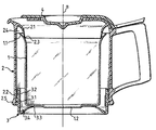
- a coffee pot of the type according to the invention suitable for use in coffee machines with a hotplate shows, this consists of a non-heat-insulating inner container 1, preferably made of glass, which is enclosed by the outer shell composed of the upper part 2 and the bottom part 3.
- the top of the jug can be closed with a lid 4.
- a circumferential collar 2 is formed on the upper part 2, which overlaps the edge 1.1 of the container 1 and, with its inner edge 2.3, rests in a form-fitting, sealing manner on the inside of the container edge 1.1 under elastic prestress.
- the upper edge 1.1 of the container 1 is designed to be inclined outwards, so that the inner edge 2.3 of the collar 2.1 is supported on it in a form-fitting manner under radial as well as under axial elastic prestress.
- stiffening ribs 2.4 are formed which influence the flexibility of the collar 2.1 and can also serve as a stop for the upper edge of the container.
- the bottom part 3 inserted into the outer shell upper part 2 from below has a circumferential radial projection 3.1 with an approximately triangular cross section, which is supported in a form-fitting, sealing manner on the inside of the reinforced upper part edge 2.5 under radial pressure.
- the ring-shaped outer shell upper part 3, which leaves the container bottom 1.2 free, is supported with its inner edge 3.3 designed as a sealing lip in a form-fitting, all-round manner on the edge region of the container bottom 1.2.
- stiffening ribs 3.4 can be provided, by means of which the hardness of this support can be influenced.
Landscapes
- Table Devices Or Equipment (AREA)
- Packages (AREA)
- Apparatus For Making Beverages (AREA)
Claims (16)
Applications Claiming Priority (2)
| Application Number | Priority Date | Filing Date | Title |
|---|---|---|---|
| DE3434331 | 1984-09-19 | ||
| DE19843434331 DE3434331A1 (de) | 1984-09-19 | 1984-09-19 | Warmhaltekanne |
Publications (2)
| Publication Number | Publication Date |
|---|---|
| EP0175231A1 EP0175231A1 (fr) | 1986-03-26 |
| EP0175231B1 true EP0175231B1 (fr) | 1988-05-11 |
Family
ID=6245760
Family Applications (1)
| Application Number | Title | Priority Date | Filing Date |
|---|---|---|---|
| EP85111266A Expired EP0175231B1 (fr) | 1984-09-19 | 1985-09-06 | Récipient calorifugé |
Country Status (4)
| Country | Link |
|---|---|
| US (1) | US4718566A (fr) |
| EP (1) | EP0175231B1 (fr) |
| CA (1) | CA1251745A (fr) |
| DE (2) | DE3434331A1 (fr) |
Families Citing this family (24)
| Publication number | Priority date | Publication date | Assignee | Title |
|---|---|---|---|---|
| GB2230334B (en) * | 1989-05-26 | 1992-01-02 | Manx Ices Ltd | Improvements in packaging |
| DE4013359A1 (de) * | 1989-12-07 | 1991-06-13 | Braun Ag | Warmhaltekanne |
| GB2267144A (en) * | 1992-05-22 | 1993-11-24 | Thermos Ltd | Vacuum flask |
| CA2169135A1 (fr) * | 1995-07-19 | 1997-01-20 | Colin Overy | Etancheite pour doublure thermique interne d'une carafe |
| USD385793S (en) * | 1996-08-05 | 1997-11-04 | Revlon Consumer Products Corporation | Combined container and cap |
| US5968618A (en) * | 1998-04-13 | 1999-10-19 | Miller; Blair J. | Thermal coffee carafe |
| US6301961B1 (en) * | 1999-08-26 | 2001-10-16 | Patrick J. Rolfes | Insulated beverage carafe with volume indicator |
| US20100288777A1 (en) * | 2006-03-23 | 2010-11-18 | Breville Pty Limited | Filter Coffee Maker |
| US20110163128A1 (en) * | 2007-08-09 | 2011-07-07 | Asahi Breweries, Ltd. | Beverage container and cooling system for the same |
| US9504349B2 (en) * | 2008-06-12 | 2016-11-29 | Breville Pty Ltd | Carafe with off centre opening |
| CH705594A1 (de) | 2011-10-04 | 2013-04-15 | Pi Design Ag | Doppelwandiger Flüssigkeitsbehälter. |
| EP2991529A4 (fr) * | 2013-04-30 | 2017-03-22 | Breville PTY Limited | Appareil de carafe chauffé à deux parois et procédé |
| DE202014103261U1 (de) * | 2014-07-15 | 2015-10-19 | Emsa Gmbh | Kanne mit einem Deckel und einem Grundkörper |
| USD861408S1 (en) | 2018-05-16 | 2019-10-01 | William Evans Retail Ltd. | Kettle |
| USD906758S1 (en) | 2018-05-16 | 2021-01-05 | William Evans Retail LTD | Lid assembly for water kettle |
| USD862147S1 (en) | 2018-05-16 | 2019-10-08 | William Evans Retail, Ltd | Kettle |
| USD935838S1 (en) | 2018-05-16 | 2021-11-16 | William Evans Retail LTD | Lid assembly for water kettle |
| USD957899S1 (en) | 2019-11-11 | 2022-07-19 | William Evans Retail LTD | Food scoop on a food storage container |
| USD958608S1 (en) | 2019-11-11 | 2022-07-26 | William Evans Retail LTD | Food storage container |
| USD966036S1 (en) | 2019-11-11 | 2022-10-11 | William Evans Retail LTD | Lid for food storage container |
| USD958589S1 (en) | 2019-11-11 | 2022-07-26 | William Evans Retail LTD | Clip for food storage container |
| CN112890571B (zh) * | 2021-02-05 | 2021-12-17 | 长沙理工大学 | 一种带有防烫伤结构的自热火锅 |
| US11779156B2 (en) | 2021-02-12 | 2023-10-10 | Sprogo Llc | Reusable beverage container assembly |
| USD1022598S1 (en) | 2021-02-12 | 2024-04-16 | Sprogo Llc | Beverage container assembly |
Family Cites Families (33)
| Publication number | Priority date | Publication date | Assignee | Title |
|---|---|---|---|---|
| US8658A (en) * | 1852-01-13 | Improvement in apparatus for attaching pieces of metal to each other by casting | ||
| BE525124A (fr) * | ||||
| US1712228A (en) * | 1928-03-12 | 1929-05-07 | Aurin E Payson | Bottle casing |
| GB327838A (en) * | 1929-03-19 | 1930-04-17 | American Thermos Bottle Co | Improvements in and relating to casings for vacuum-jacketed bottles and like vessels |
| US1935969A (en) * | 1931-02-24 | 1933-11-21 | Lillian S Witherspoon | Container |
| GB466676A (en) * | 1936-02-14 | 1937-06-02 | Eclipse Novelties Ltd | An improved cosy for tea-pots |
| US2328338A (en) * | 1942-01-21 | 1943-08-31 | Wesley R Hauptman | Cologne container |
| US2805561A (en) * | 1954-04-09 | 1957-09-10 | Emmert | Pitcher construction |
| US2837232A (en) * | 1956-04-30 | 1958-06-03 | Parfour Inc | Thermal container for bottles and other containers |
| CH359860A (de) * | 1957-01-08 | 1962-01-31 | Leslie Smith Laurance | Dicht abschliessbarer Behälter |
| US2895636A (en) * | 1957-07-24 | 1959-07-21 | James M Martin | Heat and cold retaining glasses, mugs, bowls and the like |
| US2954888A (en) * | 1957-09-30 | 1960-10-04 | Aladdin Ind Inc | Plastic-jacketed vacuum bottle |
| DE1123804B (de) * | 1958-02-27 | 1962-02-15 | Gerdes & Co | Isolierflasche |
| US3115263A (en) * | 1961-06-15 | 1963-12-24 | Leslie-Smith Laurance | Containers |
| FR1306920A (fr) * | 1961-11-23 | 1962-10-19 | Southern California Plastic Co | Perfectionnements apportés aux récipients calorifugés et à leurs procédés de fabrication |
| US3221915A (en) * | 1962-08-08 | 1965-12-07 | Corning Fibre Box | Impact-resistant glass-lined containers |
| US3145708A (en) * | 1962-09-24 | 1964-08-25 | Carson Mfg Co | Brewing vessel and protector therefor |
| US3258147A (en) * | 1964-08-20 | 1966-06-28 | Aladdin Ind Inc | Vacuum bottles having fillers with plastic liners |
| DE1679148A1 (de) * | 1967-08-04 | 1971-04-01 | Anso Zimmermann Kg Isolierflas | Isolierbehaelter |
| US3476277A (en) * | 1967-12-26 | 1969-11-04 | Robert M Rownd | Vacuum bottles having improved bottom closures |
| US3638820A (en) * | 1969-11-28 | 1972-02-01 | Sadayuki Misu | Vacuum bottle |
| US3813757A (en) * | 1971-09-01 | 1974-06-04 | King Seeley Thermos Co | Method of coating a vacuum bottle |
| DE7336476U (de) * | 1973-10-10 | 1974-02-07 | Zimmermann Kg | Isolierbehälter |
| US3871543A (en) * | 1974-01-02 | 1975-03-18 | Federal Package Corp | Double-wall jar |
| DE7425086U (de) * | 1974-07-23 | 1974-11-21 | Zitzmann C & Co | Isolierkanne |
| DE2658295C3 (de) * | 1976-12-22 | 1980-09-25 | Bosch-Siemens Hausgeraete Gmbh, 7000 Stuttgart | Kaffeekanne, insbesondere zur Verwendung in einer elektrischen Kaffeemaschine |
| DE7729773U1 (fr) * | 1977-09-26 | 1978-02-09 | Hartolit Adalbert Schmitt, 6983 Kreuzwertheim | |
| DE2952557C2 (de) * | 1979-12-28 | 1982-04-29 | Bosch-Siemens Hausgeräte GmbH, 7000 Stuttgart | Spannelement zum Verbinden von Teilen, insbesondere von Teilen bei Haushaltgeräten |
| FR2474851A1 (fr) * | 1980-02-04 | 1981-08-07 | Bozet Willy | Perfectionnement aux recipients culinaires pour batterie de cuisine |
| DE3045896C2 (de) * | 1980-12-05 | 1983-03-24 | Braun Ag, 6000 Frankfurt | Thermoskanne |
| DE8112201U1 (de) * | 1981-04-24 | 1981-09-10 | Rowenta-Werke Gmbh, 6050 Offenbach | Isolierkanne |
| GB2098854A (en) * | 1981-05-13 | 1982-12-01 | Milkon Products Ltd | Bottle container |
| DE3347481C2 (de) * | 1983-01-31 | 1985-10-17 | Rotpunkt Dr. Anso Zimmermann, 6434 Niederaula | Isolierkanne |
-
1984
- 1984-09-19 DE DE19843434331 patent/DE3434331A1/de not_active Withdrawn
-
1985
- 1985-08-26 CA CA000489409A patent/CA1251745A/fr not_active Expired
- 1985-09-06 EP EP85111266A patent/EP0175231B1/fr not_active Expired
- 1985-09-06 DE DE8585111266T patent/DE3562548D1/de not_active Expired
-
1986
- 1986-12-31 US US06/948,107 patent/US4718566A/en not_active Expired - Fee Related
Also Published As
| Publication number | Publication date |
|---|---|
| EP0175231A1 (fr) | 1986-03-26 |
| DE3562548D1 (en) | 1988-06-16 |
| CA1251745A (fr) | 1989-03-28 |
| US4718566A (en) | 1988-01-12 |
| DE3434331A1 (de) | 1986-03-27 |
Similar Documents
| Publication | Publication Date | Title |
|---|---|---|
| EP0175231B1 (fr) | Récipient calorifugé | |
| DE3929848C2 (fr) | ||
| DE3605185A1 (de) | Umlaufender daempfer | |
| DE3213890C2 (de) | Drosselklappenventil | |
| DE69704590T2 (de) | Hydraulische Dämpfungsvorrichtung | |
| DE3217732C2 (fr) | ||
| CH442129A (de) | Aus Kunststoff hergestelltes Druckgefäss, insbesondere Bierfass | |
| DD233937A5 (de) | Isoliergefaess, insbesondere isolierflasche | |
| DE3782759T2 (de) | Kugelbahn. | |
| DE202020100600U1 (de) | Behälter mit Fixierring für den Transport und die Lagerung von Flüssigkeiten | |
| DE1927276A1 (de) | Kegelrollenlager | |
| EP0110057A2 (fr) | Bouchon fileté pour récipient isolant avec corps creux perforé | |
| EP0480202B1 (fr) | Dispositif de fermeture et/ou de régulation pour la busette de récipients contenant du métal | |
| DE3829865A1 (de) | Filtereinrichtung fuer kaffee, tee od. dgl. | |
| DE2036243A1 (de) | Gleitringdichtung | |
| DE1991950U (de) | Selbsttätiges Druckausgleichsventil | |
| DE1525951A1 (de) | Dichtungsanordnung fuer druckdichtende Deckel | |
| DE8633675U1 (de) | Flaschenzelle | |
| DE1129077B (de) | Verschluss- oder Giesstuelle | |
| CH237603A (de) | Bajonett-Verschluss an einem Blechbehälter. | |
| EP1099650B1 (fr) | Couvercle pour trou d'homme d'une cuve du réacteur émaillée résistant à la corrosion et aux températures élevées | |
| AT84079B (de) | Milchkanne. | |
| DE2321224A1 (de) | Kopf fuer schaumsyphonflaschen | |
| CH429477A (de) | Verschluss an einem unter innerem Überdruck stehenden Behälter | |
| DE3937461A1 (de) | Glaskanne mit einem griff |
Legal Events
| Date | Code | Title | Description |
|---|---|---|---|
| PUAI | Public reference made under article 153(3) epc to a published international application that has entered the european phase |
Free format text: ORIGINAL CODE: 0009012 |
|
| AK | Designated contracting states |
Kind code of ref document: A1 Designated state(s): DE FR GB IT NL |
|
| 17P | Request for examination filed |
Effective date: 19860908 |
|
| 17Q | First examination report despatched |
Effective date: 19871030 |
|
| ITF | It: translation for a ep patent filed | ||
| GRAA | (expected) grant |
Free format text: ORIGINAL CODE: 0009210 |
|
| AK | Designated contracting states |
Kind code of ref document: B1 Designated state(s): DE FR GB IT NL |
|
| GBT | Gb: translation of ep patent filed (gb section 77(6)(a)/1977) | ||
| REF | Corresponds to: |
Ref document number: 3562548 Country of ref document: DE Date of ref document: 19880616 |
|
| ET | Fr: translation filed | ||
| PLBE | No opposition filed within time limit |
Free format text: ORIGINAL CODE: 0009261 |
|
| STAA | Information on the status of an ep patent application or granted ep patent |
Free format text: STATUS: NO OPPOSITION FILED WITHIN TIME LIMIT |
|
| 26N | No opposition filed | ||
| ITTA | It: last paid annual fee | ||
| PGFP | Annual fee paid to national office [announced via postgrant information from national office to epo] |
Ref country code: GB Payment date: 19950817 Year of fee payment: 11 |
|
| PGFP | Annual fee paid to national office [announced via postgrant information from national office to epo] |
Ref country code: FR Payment date: 19950904 Year of fee payment: 11 |
|
| PGFP | Annual fee paid to national office [announced via postgrant information from national office to epo] |
Ref country code: NL Payment date: 19950911 Year of fee payment: 11 |
|
| PGFP | Annual fee paid to national office [announced via postgrant information from national office to epo] |
Ref country code: DE Payment date: 19960805 Year of fee payment: 12 |
|
| PG25 | Lapsed in a contracting state [announced via postgrant information from national office to epo] |
Ref country code: GB Effective date: 19960906 |
|
| PG25 | Lapsed in a contracting state [announced via postgrant information from national office to epo] |
Ref country code: FR Effective date: 19960930 |
|
| PG25 | Lapsed in a contracting state [announced via postgrant information from national office to epo] |
Ref country code: NL Effective date: 19970401 |
|
| GBPC | Gb: european patent ceased through non-payment of renewal fee |
Effective date: 19960906 |
|
| NLV4 | Nl: lapsed or anulled due to non-payment of the annual fee |
Effective date: 19970401 |
|
| REG | Reference to a national code |
Ref country code: FR Ref legal event code: ST |
|
| REG | Reference to a national code |
Ref country code: FR Ref legal event code: ST |
|
| PG25 | Lapsed in a contracting state [announced via postgrant information from national office to epo] |
Ref country code: DE Free format text: LAPSE BECAUSE OF NON-PAYMENT OF DUE FEES Effective date: 19980603 |