EP0175378A2 - Dynamische Speicherzelle mit wahlfreiem Zugriff (DRAM) - Google Patents
Dynamische Speicherzelle mit wahlfreiem Zugriff (DRAM) Download PDFInfo
- Publication number
- EP0175378A2 EP0175378A2 EP85111909A EP85111909A EP0175378A2 EP 0175378 A2 EP0175378 A2 EP 0175378A2 EP 85111909 A EP85111909 A EP 85111909A EP 85111909 A EP85111909 A EP 85111909A EP 0175378 A2 EP0175378 A2 EP 0175378A2
- Authority
- EP
- European Patent Office
- Prior art keywords
- transistor
- write
- cell
- read
- read select
- Prior art date
- Legal status (The legal status is an assumption and is not a legal conclusion. Google has not performed a legal analysis and makes no representation as to the accuracy of the status listed.)
- Granted
Links
Images
Classifications
-
- H—ELECTRICITY
- H10—SEMICONDUCTOR DEVICES; ELECTRIC SOLID-STATE DEVICES NOT OTHERWISE PROVIDED FOR
- H10B—ELECTRONIC MEMORY DEVICES
- H10B12/00—Dynamic random access memory [DRAM] devices
- H10B12/20—DRAM devices comprising floating-body transistors, e.g. floating-body cells
-
- H—ELECTRICITY
- H10—SEMICONDUCTOR DEVICES; ELECTRIC SOLID-STATE DEVICES NOT OTHERWISE PROVIDED FOR
- H10D—INORGANIC ELECTRIC SEMICONDUCTOR DEVICES
- H10D88/00—Three-dimensional [3D] integrated devices
-
- G—PHYSICS
- G11—INFORMATION STORAGE
- G11C—STATIC STORES
- G11C11/00—Digital stores characterised by the use of particular electric or magnetic storage elements; Storage elements therefor
- G11C11/21—Digital stores characterised by the use of particular electric or magnetic storage elements; Storage elements therefor using electric elements
- G11C11/34—Digital stores characterised by the use of particular electric or magnetic storage elements; Storage elements therefor using electric elements using semiconductor devices
- G11C11/40—Digital stores characterised by the use of particular electric or magnetic storage elements; Storage elements therefor using electric elements using semiconductor devices using transistors
- G11C11/401—Digital stores characterised by the use of particular electric or magnetic storage elements; Storage elements therefor using electric elements using semiconductor devices using transistors forming cells needing refreshing or charge regeneration, i.e. dynamic cells
- G11C11/403—Digital stores characterised by the use of particular electric or magnetic storage elements; Storage elements therefor using electric elements using semiconductor devices using transistors forming cells needing refreshing or charge regeneration, i.e. dynamic cells with charge regeneration common to a multiplicity of memory cells, i.e. external refresh
- G11C11/405—Digital stores characterised by the use of particular electric or magnetic storage elements; Storage elements therefor using electric elements using semiconductor devices using transistors forming cells needing refreshing or charge regeneration, i.e. dynamic cells with charge regeneration common to a multiplicity of memory cells, i.e. external refresh with three charge-transfer gates, e.g. MOS transistors, per cell
-
- H—ELECTRICITY
- H10—SEMICONDUCTOR DEVICES; ELECTRIC SOLID-STATE DEVICES NOT OTHERWISE PROVIDED FOR
- H10B—ELECTRONIC MEMORY DEVICES
- H10B12/00—Dynamic random access memory [DRAM] devices
-
- H—ELECTRICITY
- H10—SEMICONDUCTOR DEVICES; ELECTRIC SOLID-STATE DEVICES NOT OTHERWISE PROVIDED FOR
- H10B—ELECTRONIC MEMORY DEVICES
- H10B12/00—Dynamic random access memory [DRAM] devices
- H10B12/01—Manufacture or treatment
Definitions
- the present invention relates to dynamic random access memory (hereafter DRAM) devices.
- RAM Random access memory
- MOS metal- oxide-transistor
- static MOS RAMs MOS RAMs
- dynamic MOS RAMs A static MOS memory (RAM) usually has a relatively high speed of operation and a rather higher power dissipation as compared with a dynamic memory circuit (RAM).
- DRAM dynamic MOS RAM
- DRAMs need occupy less area on a substrate, being suitable for achieving high packing density, and has lesser power consumption, although its speed of operation is rather lower and more elaborate control circuits are required in comparison with a static RAM.
- DRAMs are increasingly used as storage devices of high capacity for electronic devices.
- a DRAM cell having only a single transistor has been developed and widely used.
- Such a one transistor memory cell requires only two control lines, a bit line and a word line.
- it requires a sensitive sense amplifier, because an output signal of the cell is read out as a potential differential of the associated bit line provided by a stored charge in a capacitor of the cell.
- a greater part of the electrical charge stored in the cell is consumed to charge up the parasitic capacity of the bit line, which means that only a small potential differential can be attained: namely a very faint output signal.
- a three-transistor cell is one DRAM cell type recently proposed.
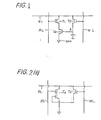
- Fig. 1 is a schematic diagram of a previously proposed three-transistor memory cell, having a shared read/ write (R/W) data bit line DL.
- the cell also has a read select line RL and a separate write select line WL.
- information is stored as the potential level of the gate of a storage transistor T 3 , which is generated in dependence upon stored charges in the gate electrode, and the stored information is output by making a read select transistor T 1 conductive, for example so as to discharge the data bit line DL to ground potential when the storage transistor T 3 is also conductive.
- an output signal potential differential (the difference between the voltage levels of the data bit line DL for different stored information values) can be substantially greater than the output signal potential differential available with a one-transistor cell.
- a simple sense-amplifier is sufficient to detect the output signal, which means that the sense-amplifier region can be reduced in size, providing a higher packing density in this respect.
- the numbers of transistors and lines used for a cell are larger than those used for a one-transistor cell. When these elements and lines are arranged in a plane, the cell occupies a relatively large area, adversely affecting the packing density of a device using such cells.
- a three-transistor cell for a dynamic random access memory comprising
- An embodiment of the present invention can provide a three-transistor cell for a DRAM having a structure enabling a higher packing density to be achieved for the DRAM device.
- An embodiment of the present invention can provide a three-transistor cell for a DRAM with a two-storied structure wherein an arrangement of elements and associated control lines of the cell is provided which is effective to reduce the area of the cell.
- An embodiment of the present invention can provide a configuration for a three-transistor cell of a DRAM device which enables a reduction of the number of control lines from three to two (not including a ground line).
- An embodiment of the present invention provides a structure for a cell of a DRAM device wherein electrical elements are arranged in a two-storied configuration such that a high packing density can be realized.
- Embodiments of the present invention provide such two-storied structures of three transistor cells of DRAMS whereby the cells have either three or two driving lines besides a ground line.
- transistor T 1 and transistor T 3 are both conductive when reading a stored signal "O", passing a current through the T 1 -T 3 circuit between data bit line DL and ground line GND, but that transistor T 1 is conductive and transistor T 3 is non-conductive when a stored signal "1" is read and in this case no current flows through the T 1 -T 3 circuit.
- a dual gate field effect transistor can be applied in the cell of Fig. 1, by which the connection between transistor T 1 and transistor T 3 through respective source-drain regions can be omitted, serving to effect an economy as regards space on the relevant substrate of a DRAM device. This is applied in (some) embodiments of the present invention.
- two-storied or two-level structures For saving area on a substrate of a semiconductor device, two-storied or two-level structures have been utilized, wherein electronic elements are arranged in two layers separated from one another by an insulator layer.
- a read select transistor T 1 , a storage transistor T 3 , and a read select line RL which acts as a gate electrode of transistor T 1 are formed directly on the surface of a silicon substrate, i.e. on a first storey or level, whilst a write select transistor T 2 and a write (word) select line WL which acts as a gate of transistor T 2 are formed on a second storey, on an insulator layer separating the first and second stories.
- a data bit line DL is formed on a phospho-silicate glass layer covering the entire substrate.
- the arrangement of the transistors is such that the write select transistor T 2 overlies the read select transistor T 1' and a common channel region is formed partially overlaid by the gates of read select transistor T 1 and storage transistor T 3 .
- the transistors T 1 and T 3 act like a dual gate transistor.
- the connecting portion between the two transistors usually including at least source-drain regions, a remarkable saving is made.
- one of the source-drain regions of transistor T 2 is utilized also as the gate electrode of transistor T 3 , serving to save space on the substrate.
- a circuit configuration of a DRAM cell wherein the number of control lines of a memory cell is reduced from three to two; namely, a shared write/read bit line and a shared write/read select line, and two cell transistors having different threshold voltages from each other are used.
- a DRAM cell having a further simplified two-storied structure is provided in accordance with the circuit configuration of the cell.
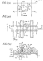
- Fig. 2 (a) is a circuit diagram of a memory cell of a DRAM; having three transistors and three control lines, whose configuration is quite similar to that of a previously proposed three transistor cell as shown in Fig. 1, except in relation to reference signs or indications Ch1, Ch3 denoting channel regions and in relation to reference signs or indications 3a, 3b, 9a and 9b denoting source-drain regions of respective transistors. These indications respectively correspond to those illustrated in the plan view of Fig. 2 (b) and the cross-sectional view of Fig. 2 (c).
- a MOS transistor T1 namely a read select transistor, comprises the drain region 3a, channel region Ch1, channel region Ch3 as its source region, a channel (gate) insulator layer 4 0 of silicon dioxide (Si0 2 ) approximately 300 A thick formed over the channel region Ch1, and a gate electrode 5 made of tungsten-silicide (WSi 2 ) or polycrystalline silicon, for instance.
- the gate electrode 5 of transistor T 1 is covered by an insulator layer 6 of Si0 2 having a thickness of approximately 6000 A, over which a write select transistor T 2 is formed.
- the write select transistor T 2 overlaid on the read select transistor T 1 comprises a first diffusion region 9a of n+ type (drain region), a second diffusion region 9b of n+ type (source region), a gate insulator 10 0 of Si0 2 having a thickness of approximately 300 A, a channel region Ch2 or 8 and a gate electrode 11.
- the silicon layer 8 of p type has a thickness of 5000 to 8000 A, being formed using a silicon-on-insulator (SOI) technology.
- SOI silicon-on-insulator
- the first diffusion region 9a and the second diffusion region 9b are formed in the silicon layer 8.
- the region 9a reaches an insulator layer 7 of Si0 2 having a thickness of approximately 300 A and is connected to the drain region 3a of read select transistor T 1 through a contact window 13a (Fig. 2 (c), see also 13 in Fig. 2 (b)).
- a storage transistor T 3 comprises the source region 3b, a drain region Ch1 which is used commonly with the read select transistor T 1 , the insulator layer 7 (as gate insulator), the channel region Ch3, and a gate electrode 9b which is commonly used as the source region of the write select transistor T 2 .
- the combined device comprising the read select transistor T 1 and the storage transistor T 3 can be regarded as a dual gate field effect transistor, comprising a drain region 3a, a source region 3b, a channel region Ch1 plus Ch3, two gate insulators 4,7 and two gate electrodes 5,9b.
- the write select transistor T 2 overlaying the write select transistor T 2 over the read select transistor T 1 , one of the source region and the drain region of the transistor T 2 is commonly used as the gate electrode of the storage transistor T 3 .
- the gate electrode 5 of the read select transistor T 1 and the gate electrode 11 of the write select transistor T 2 are extended in a Y direction (indicated by an arrow marked Y in Fig. 2 (b)) to play the roles of a read select line RL and a word select line WL respectively.
- a phospho-silicate glass layer 12 is formed to cover the transistors and lines of the device, and a data bit line DL 14 of aluminium is formed thereon in a direction perpendicular to the Y-direction, being connected to the drain regions 9a and 3a through a contact hole 13b (Fig. 2 (c), see also 13 in Fig. 2 (b)) opened in the phospho-silicate glass layer 12.
- the source region 3b is extended to serve as a ground line GND as shown in the plan view of Fig. 2 (b).
- the circuit configuration shown in Fig. 2 (a) is realized.
- the data bit line DL is maintained at a high level and the write select line WL, namely the gate electrode 11 of the write select transistor T 21 is brought to a higher voltage level to make the write select transistor T 2 "ON", bringing the gate electrode 9b of the storage transistor T 3 to high level to keep the transistor T 3 in "ON” state. Thereafter, the write select transistor T 2 is made “OFF” to keep the voltage level of the gate electrode 9b of the storage transistor T 3 high, storing the logical "O".
- the data bit line DL When reading a stored logical "O" from the cell, the data bit line DL is brought to a predetermined voltage level such as an intermediate voltage Vm level between high level and low level and kept floating. Thereafter, the read select transistor T 1 is made “ON". Since the storage transistor T 3 is in an "ON" state, a current flows from the data bit line DL to the ground line GND through the read select transistor T 1 and the storage transistor T 3 substantially pulling down the voltage of the data bit line DL to the ground voltage. The reduction of the voltage of the data bit line DL represents the logical "O".
- the data bit line DL is maintained at a low voltage level, and simultaneously the write select transistor T 2 is made “ON”, making the voltage level of the gate of the storage transistor T 3 low. Then, the write select transistor T 2 is made “OFF” thereafter, maintaining the gate voltage level of the storage transistor T 3 low, namely, maintaining the storage transistor T 3 in "OFF" state.
- the data bit line DL When reading out the logical "1" from the cell, the data bit line DL is maintained at the voltage level Vm, for instance, and the read select transistor T 1 is made “ON". Since the storage transistor T 3 is "OFF" state, no current flows through the circuit storage transistor T 3 plus read select transistor T 1 , maintaining the voltage of the data bit line DL at Vm, providing no voltage difference (no pull-down of the data bit line voltage) which represents the logical "1".
- the circuitry of the first embodiment of the present invention operates in the same manner as that of a previously prepared DRAM cell.
- the storage transistor T 3 and the read select transistor T 1 co-possess their channel regions Ch3 and Ch1, eliminating diffusion regions for connecting the two transistors.
- one of the source-drain regions of the write select transistor T 2 is commonly used as the gate electrode of the storage transistor T 3 . As the result, a remarkable reduction in cell area can be achieved, enabling packing density to be increased significantly.
- the gate electrode 9b of the storage transistor T 3 wherein information is stored in the form of electrical charges is electrically isolated from the substrate 1 by the surrounding silicon dioxide layer 6 and 7, resulting in an effect which serves for preventing soft error problems, due to alpha ray irradiation.
- circuit configuration of Fig. 2 (a) can be illustrated in another configuration as shown in Fig. 2 (d), wherein the read select transistor T 1 and the storage transistor T 3 are replaced by a dual-gate electrode MOS transistor T d . It will be apparent from the above description of the first embodiment of the present invention, for those skilled in the art, that both circuit configurations are entirely the same with regard to circuit operation.
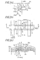
- the memory cell of the second embodiment has three transistors and two control lines as shown in the circuit diagram of Fig. 3 (a).
- the read select line RL and write select line WL of Fig. 2 (a) are replaced by a single line, write/read select line WRL to which the gate electrodes of a write select transistor T 2 and read select transistor T 1 are connected. Therefore, in order to distinguish these two transistors from each other, the threshold voltages of the two transistors T 1 and T 2 , namely V th1 and V th2 respectively, are made different from each other.
- control lines are reduced by one, and the resulting cell structure is further simplified.
- Fig. 3 (b) is a partial plan view of a DRAM device, illustrating the configuration of a memory cell in accordance with the second embodiment
- Fig. 3 (c) is a cross-sectional view of the cell taken along the line A-A shown in the partial plan view of Fig. 3 (b).
- Threshold voltages of transistors T1, T 2 and T 3 are designated by V th1' V th2 and V th3 respectively, and voltage levels of write/read select line WRL for selecting a reading or a writing operation are designated by V r and V respectively.
- the voltage level of the data bit line DL, namely a data signal is designated by V d .
- T 2 When writing an information signal (e.g. "0" or "1") into the cell, T 2 is made conductive by holding the write/ read select line WRL at V w . Thereafter, an input signal voltage, 0 volt or Vd, is applied to the data bit line DL, namely, to the gate of T 3 , depending on the input logical value to be written, resulting in an "OFF" state or an “ON” state of the storage transistor T 3 . In this circuit configuration, the read select transistor T 1 is made also conductive simultaneously.
- two-storied structures and circuit configurations in accordance with the present invention can provide for high packing densities in associated DRAM devices.
- the present invention serves to provide a DRAM device with easier fabricating processes, thereby serving to reduce manufacturing costs.
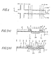
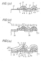
- a p-type silicon substrate 1 is prepared, and field oxide layers FOX of silicon dioxide (Si0 2 ) are formed thereon by a conventional method, defining transistor re- g ions A cell' being followed by the further formation of a first gate insulator layer 4 approximately 300 A thick over the transistor regions A cell by a conventional thermal oxidizing method.
- a tung-0 sten silicide (WSi 2 ) layer 5 approximately 2000 A thick and an Si0 2 layer 6 approximately 5000 to 8000 A thick are formed subsequently by conventional chemical vapour deposition (CVD).
- CVD chemical vapour deposition
- a gate electrode 5 for read select transistor T1 having Si0 2 insulator layer 6 thereon, is formed.
- the gate electrode 5 is extended over the substrate and plays a r6le as a read select line RL.
- a photoresist mask R (indicated by broken lines in Fig. 5 (a)) is formed to cover the area on the substrate except for predetermined regions for data bit lines.
- arsenic (As) ions are implanted into the exposed areas of the silicon substrate with a dose of 5X10 15 cm -2 and an accelerating energy of 100 KeV, this being followed by removal of the photoresist mask R and by appropriate heat processing for diffusing the implanted As dopants to form a n type drain region 3a.
- the exposed surface (uncovered by the patterned gate electrode 5 on the Si0 2 layer (the gate insulator layer 4)) is etched off by a conventional wet etching method. Then a second gate insulator layer of Si0 2 approximately 300 A thick is formed by a conventional thermal oxidizing method. Hereby, on the side wall of the gate electrode 5, a rather thick Si0 2 layer approximately 500 A is formed.
- a contact window 13a is opened in the second gate insulator layer 7 over the n+ type drain region 3a, this being followed by the formation of a thick 0 polycrystalline silicon layer 8 approximately 5000 A thick over the entire surface of the substrate 1.
- the polycrystalline silicon layer is converted to a single crystal layer by irradiation with a laser beam or an electron beam having a predetermined energy for heating.
- This is one of the SOI (silicon on insulator) technologies and the single crystal silicon layer is referred to as an SOI layer 8 which serves to form an MOS FET having a small gate leakage current.
- the SOI layer 8 is doped, to become a p-type diffusion layer with 10 16 cm dopant density, by boron (B+) ion implantation and subsequent heat treatment.
- a polycrystalline silicon layer formed on the entire substrate by a conventional CVD method may be converted into a layer of single crystal silicon structure by re-crystallization using a heat treatment at approximately 600 °C whereby the exposed single crystal structure of the contact region acts as seed for the re-crystallization.
- a third gate 0 insulator region 10 approximately 300 A thick is formed by a thermal oxidizing method. This step is followed by a chemical vapour deposition (CVD) process to form a 0 tungsten silicide (WSi 2 ) layer of approximately 2000 A thickness, accompanied by a photolithographic process for patterning a gate electrode 11 of a write select transistor T 2 .
- the gate electrode 11 is extended to play a role as a word select line WL.
- n+ type region 9a As a drain region of write select transistor T 2
- second n+ region 9b As a source region of write select transistor T 2
- an n+ type source region 3b The source region 3b of storage transistor T 3 is extended to act as a ground line.
- the above-described n+ type regions 9a and 9b are formed to reach the underlying SOI layer 8.
- a phospho-silicate glass layer 12 by a conventional method, and a contact window 13b is formed to expose the underlying drain region 3a of read select transistor T 1 .
- a data bit line DL of aluminium or other metal is formed over the phospho-silicate glass layer 12 so that the data bit line DL is connected to the drain region 9a of write select transistor T 2 and the drain region 3a of read select transistor T 1 through the contact window 13b.
- formation of a passivating layer for the substrate and other final processes are performed to complete the semiconductor memory device.
- a dynamic random access memory (DRAM) cell having three MIS transistors arranged in two-storied layers having a high packing density configuration is disclosed.
- a write select transistor is disposed overlying a read select transistor, being electrically separated from each other through an insulator layer, and a drain region of the write select transistor is shared with the underlying read select transistor as its gate electrode.
- a storage transistor and the read select transistor are formed on a silicon substrate in the same level and channel regions of both transistors are connected to each other and used as a diffusion region of the opposite transistor, resulting in elimination of connecting members such as diffusion regions and a conducting path therebetween which were otherwise necessary. These two points contribute to elevate the packing density of the cell.
- a write select line and a read select line are combined into a single control line: write/read select line, saving one line to obtain higher packing density.
- gate electrodes of both transistors are connected to the write/read line. These transistors are distinguished from each other by their different threshold voltage levels from each other.
Landscapes
- Engineering & Computer Science (AREA)
- Microelectronics & Electronic Packaging (AREA)
- Computer Hardware Design (AREA)
- Manufacturing & Machinery (AREA)
- Semiconductor Memories (AREA)
- Dram (AREA)
- Recrystallisation Techniques (AREA)
- Metal-Oxide And Bipolar Metal-Oxide Semiconductor Integrated Circuits (AREA)
Applications Claiming Priority (2)
| Application Number | Priority Date | Filing Date | Title |
|---|---|---|---|
| JP59198840A JPS6177359A (ja) | 1984-09-21 | 1984-09-21 | 半導体記憶装置 |
| JP198840/84 | 1984-09-21 |
Publications (3)
| Publication Number | Publication Date |
|---|---|
| EP0175378A2 true EP0175378A2 (de) | 1986-03-26 |
| EP0175378A3 EP0175378A3 (en) | 1987-04-22 |
| EP0175378B1 EP0175378B1 (de) | 1991-11-21 |
Family
ID=16397789
Family Applications (1)
| Application Number | Title | Priority Date | Filing Date |
|---|---|---|---|
| EP85111909A Expired - Lifetime EP0175378B1 (de) | 1984-09-21 | 1985-09-20 | Dynamische Speicherzelle mit wahlfreiem Zugriff (DRAM) |
Country Status (5)
| Country | Link |
|---|---|
| US (1) | US4669062A (de) |
| EP (1) | EP0175378B1 (de) |
| JP (1) | JPS6177359A (de) |
| KR (1) | KR900003908B1 (de) |
| DE (1) | DE3584709D1 (de) |
Cited By (22)
| Publication number | Priority date | Publication date | Assignee | Title |
|---|---|---|---|---|
| US4910709A (en) * | 1988-08-10 | 1990-03-20 | International Business Machines Corporation | Complementary metal-oxide-semiconductor transistor and one-capacitor dynamic-random-access memory cell |
| EP0481392A3 (en) * | 1990-10-15 | 1993-01-27 | Nec Corporation | Semiconductor non-volatile memory device |
| US5396452A (en) * | 1993-07-02 | 1995-03-07 | Wahlstrom; Sven E. | Dynamic random access memory |
| US6242772B1 (en) | 1994-12-12 | 2001-06-05 | Altera Corporation | Multi-sided capacitor in an integrated circuit |
| US8861247B2 (en) | 2009-04-27 | 2014-10-14 | Micron Technology, Inc. | Techniques for providing a direct injection semiconductor memory device |
| US8947965B2 (en) | 2009-07-27 | 2015-02-03 | Micron Technology Inc. | Techniques for providing a direct injection semiconductor memory device |
| US8964479B2 (en) | 2010-03-04 | 2015-02-24 | Micron Technology, Inc. | Techniques for sensing a semiconductor memory device |
| US8982633B2 (en) | 2009-05-22 | 2015-03-17 | Micron Technology, Inc. | Techniques for providing a direct injection semiconductor memory device |
| US9019759B2 (en) | 2010-03-15 | 2015-04-28 | Micron Technology, Inc. | Techniques for providing a semiconductor memory device |
| US9019788B2 (en) | 2008-01-24 | 2015-04-28 | Micron Technology, Inc. | Techniques for accessing memory cells |
| US9064730B2 (en) | 2009-03-04 | 2015-06-23 | Micron Technology, Inc. | Techniques for forming a contact to a buried diffusion layer in a semiconductor memory device |
| US9093311B2 (en) | 2009-03-31 | 2015-07-28 | Micron Technology, Inc. | Techniques for providing a semiconductor memory device |
| US9142264B2 (en) | 2010-05-06 | 2015-09-22 | Micron Technology, Inc. | Techniques for refreshing a semiconductor memory device |
| US9240496B2 (en) | 2009-04-30 | 2016-01-19 | Micron Technology, Inc. | Semiconductor device with floating gate and electrically floating body |
| US9257155B2 (en) | 2007-05-30 | 2016-02-09 | Micron Technology, Inc. | Integrated circuit having voltage generation circuitry for memory cell array, and method of operating and/or controlling same |
| US9263133B2 (en) | 2011-05-17 | 2016-02-16 | Micron Technology, Inc. | Techniques for providing a semiconductor memory device |
| US9276000B2 (en) | 2007-03-29 | 2016-03-01 | Micron Technology, Inc. | Manufacturing process for zero-capacitor random access memory circuits |
| US9331083B2 (en) | 2009-07-10 | 2016-05-03 | Micron Technology, Inc. | Techniques for providing a semiconductor memory device |
| US9553186B2 (en) | 2008-09-25 | 2017-01-24 | Micron Technology, Inc. | Recessed gate silicon-on-insulator floating body device with self-aligned lateral isolation |
| US9812179B2 (en) | 2009-11-24 | 2017-11-07 | Ovonyx Memory Technology, Llc | Techniques for reducing disturbance in a semiconductor memory device |
| US10304837B2 (en) | 2007-11-29 | 2019-05-28 | Ovonyx Memory Technology, Llc | Integrated circuit having memory cell array including barriers, and method of manufacturing same |
| US10418091B2 (en) | 2005-09-07 | 2019-09-17 | Ovonyx Memory Technology, Llc | Memory cell and memory cell array having an electrically floating body transistor, and methods of operating same |
Families Citing this family (60)
| Publication number | Priority date | Publication date | Assignee | Title |
|---|---|---|---|---|
| JPS6319847A (ja) * | 1986-07-14 | 1988-01-27 | Oki Electric Ind Co Ltd | 半導体記憶装置 |
| JP2633541B2 (ja) * | 1987-01-07 | 1997-07-23 | 株式会社東芝 | 半導体メモリ装置の製造方法 |
| JPH01255269A (ja) * | 1988-04-05 | 1989-10-12 | Oki Electric Ind Co Ltd | 半導体記憶装置 |
| KR950008385B1 (ko) * | 1990-05-24 | 1995-07-28 | 삼성전자주식회사 | 반도체 소자의 워드라인 형성방법 |
| US5057888A (en) * | 1991-01-28 | 1991-10-15 | Micron Technology, Inc. | Double DRAM cell |
| US5345414A (en) * | 1992-01-27 | 1994-09-06 | Rohm Co., Ltd. | Semiconductor memory device having ferroelectric film |
| JPH0799251A (ja) * | 1992-12-10 | 1995-04-11 | Sony Corp | 半導体メモリセル |
| JP3424427B2 (ja) * | 1995-07-27 | 2003-07-07 | ソニー株式会社 | 不揮発性半導体メモリ装置 |
| JPH09232827A (ja) * | 1996-02-21 | 1997-09-05 | Oki Electric Ind Co Ltd | 半導体装置及び送受信切り替え型アンテナスイッチ回路 |
| KR100403798B1 (ko) * | 1996-03-11 | 2004-06-26 | 삼성전자주식회사 | 겹침형강유전체랜덤액세서메모리및그제조방법과구동방법 |
| US5882959A (en) * | 1996-10-08 | 1999-03-16 | Advanced Micro Devices, Inc. | Multi-level transistor fabrication method having an inverted, upper level transistor which shares a gate conductor with a non-inverted, lower level transistor |
| US5872029A (en) * | 1996-11-07 | 1999-02-16 | Advanced Micro Devices, Inc. | Method for forming an ultra high density inverter using a stacked transistor arrangement |
| US6169308B1 (en) | 1996-11-15 | 2001-01-02 | Hitachi, Ltd. | Semiconductor memory device and manufacturing method thereof |
| JP3554666B2 (ja) * | 1997-10-07 | 2004-08-18 | 株式会社日立製作所 | 半導体メモリ装置 |
| US6642574B2 (en) | 1997-10-07 | 2003-11-04 | Hitachi, Ltd. | Semiconductor memory device and manufacturing method thereof |
| US5761114A (en) * | 1997-02-19 | 1998-06-02 | International Business Machines Corporation | Multi-level storage gain cell with stepline |
| US5926700A (en) | 1997-05-02 | 1999-07-20 | Advanced Micro Devices, Inc. | Semiconductor fabrication having multi-level transistors and high density interconnect therebetween |
| US5818069A (en) | 1997-06-20 | 1998-10-06 | Advanced Micro Devices, Inc. | Ultra high density series-connected transistors formed on separate elevational levels |
| US5888872A (en) | 1997-06-20 | 1999-03-30 | Advanced Micro Devices, Inc. | Method for forming source drain junction areas self-aligned between a sidewall spacer and an etched lateral sidewall |
| EP1703520B1 (de) * | 1999-02-01 | 2011-07-27 | Renesas Electronics Corporation | Integrierte Halbleiterschaltung und nichtflüchtiges Speicherelement |
| TWI230392B (en) | 2001-06-18 | 2005-04-01 | Innovative Silicon Sa | Semiconductor device |
| EP1355316B1 (de) | 2002-04-18 | 2007-02-21 | Innovative Silicon SA | Datenspeichergerät sowie Verfahren zum Auffrischen der auf einem solchen Gerät gespeicherten Daten |
| EP1357603A3 (de) | 2002-04-18 | 2004-01-14 | Innovative Silicon SA | Halbleiterbauelement |
| US20040228168A1 (en) | 2003-05-13 | 2004-11-18 | Richard Ferrant | Semiconductor memory device and method of operating same |
| US7085153B2 (en) | 2003-05-13 | 2006-08-01 | Innovative Silicon S.A. | Semiconductor memory cell, array, architecture and device, and method of operating same |
| US6912150B2 (en) | 2003-05-13 | 2005-06-28 | Lionel Portman | Reference current generator, and method of programming, adjusting and/or operating same |
| US6934213B2 (en) * | 2003-06-11 | 2005-08-23 | Artisan Components, Inc. | Method and apparatus for reducing write power consumption in random access memories |
| US7335934B2 (en) | 2003-07-22 | 2008-02-26 | Innovative Silicon S.A. | Integrated circuit device, and method of fabricating same |
| US7184298B2 (en) | 2003-09-24 | 2007-02-27 | Innovative Silicon S.A. | Low power programming technique for a floating body memory transistor, memory cell, and memory array |
| KR100600878B1 (ko) * | 2004-06-29 | 2006-07-14 | 삼성에스디아이 주식회사 | 박막트랜지스터 및 그 제조방법 |
| US7476939B2 (en) | 2004-11-04 | 2009-01-13 | Innovative Silicon Isi Sa | Memory cell having an electrically floating body transistor and programming technique therefor |
| US7251164B2 (en) | 2004-11-10 | 2007-07-31 | Innovative Silicon S.A. | Circuitry for and method of improving statistical distribution of integrated circuits |
| WO2006065698A2 (en) | 2004-12-13 | 2006-06-22 | William Kenneth Waller | Sense amplifier circuitry and architecture to write data into and/or read data from memory cells |
| US7301803B2 (en) | 2004-12-22 | 2007-11-27 | Innovative Silicon S.A. | Bipolar reading technique for a memory cell having an electrically floating body transistor |
| US7355916B2 (en) | 2005-09-19 | 2008-04-08 | Innovative Silicon S.A. | Method and circuitry to generate a reference current for reading a memory cell, and device implementing same |
| US7683430B2 (en) | 2005-12-19 | 2010-03-23 | Innovative Silicon Isi Sa | Electrically floating body memory cell and array, and method of operating or controlling same |
| US7542345B2 (en) | 2006-02-16 | 2009-06-02 | Innovative Silicon Isi Sa | Multi-bit memory cell having electrically floating body transistor, and method of programming and reading same |
| US7492632B2 (en) | 2006-04-07 | 2009-02-17 | Innovative Silicon Isi Sa | Memory array having a programmable word length, and method of operating same |
| US7606098B2 (en) | 2006-04-18 | 2009-10-20 | Innovative Silicon Isi Sa | Semiconductor memory array architecture with grouped memory cells, and method of controlling same |
| US7933142B2 (en) | 2006-05-02 | 2011-04-26 | Micron Technology, Inc. | Semiconductor memory cell and array using punch-through to program and read same |
| US8069377B2 (en) | 2006-06-26 | 2011-11-29 | Micron Technology, Inc. | Integrated circuit having memory array including ECC and column redundancy and method of operating the same |
| US7542340B2 (en) | 2006-07-11 | 2009-06-02 | Innovative Silicon Isi Sa | Integrated circuit including memory array having a segmented bit line architecture and method of controlling and/or operating same |
| US8264041B2 (en) | 2007-01-26 | 2012-09-11 | Micron Technology, Inc. | Semiconductor device with electrically floating body |
| US8085594B2 (en) | 2007-06-01 | 2011-12-27 | Micron Technology, Inc. | Reading technique for memory cell with electrically floating body transistor |
| WO2009039169A1 (en) | 2007-09-17 | 2009-03-26 | Innovative Silicon S.A. | Refreshing data of memory cells with electrically floating body transistors |
| US8349662B2 (en) | 2007-12-11 | 2013-01-08 | Micron Technology, Inc. | Integrated circuit having memory cell array, and method of manufacturing same |
| US8014195B2 (en) | 2008-02-06 | 2011-09-06 | Micron Technology, Inc. | Single transistor memory cell |
| US8189376B2 (en) | 2008-02-08 | 2012-05-29 | Micron Technology, Inc. | Integrated circuit having memory cells including gate material having high work function, and method of manufacturing same |
| US7957206B2 (en) | 2008-04-04 | 2011-06-07 | Micron Technology, Inc. | Read circuitry for an integrated circuit having memory cells and/or a memory cell array, and method of operating same |
| US7933140B2 (en) | 2008-10-02 | 2011-04-26 | Micron Technology, Inc. | Techniques for reducing a voltage swing |
| US7924630B2 (en) | 2008-10-15 | 2011-04-12 | Micron Technology, Inc. | Techniques for simultaneously driving a plurality of source lines |
| US8223574B2 (en) | 2008-11-05 | 2012-07-17 | Micron Technology, Inc. | Techniques for block refreshing a semiconductor memory device |
| US8213226B2 (en) | 2008-12-05 | 2012-07-03 | Micron Technology, Inc. | Vertical transistor memory cell and array |
| US8319294B2 (en) | 2009-02-18 | 2012-11-27 | Micron Technology, Inc. | Techniques for providing a source line plane |
| US8199595B2 (en) | 2009-09-04 | 2012-06-12 | Micron Technology, Inc. | Techniques for sensing a semiconductor memory device |
| US8310893B2 (en) | 2009-12-16 | 2012-11-13 | Micron Technology, Inc. | Techniques for reducing impact of array disturbs in a semiconductor memory device |
| US8416636B2 (en) | 2010-02-12 | 2013-04-09 | Micron Technology, Inc. | Techniques for controlling a semiconductor memory device |
| US8411513B2 (en) | 2010-03-04 | 2013-04-02 | Micron Technology, Inc. | Techniques for providing a semiconductor memory device having hierarchical bit lines |
| US8369177B2 (en) | 2010-03-05 | 2013-02-05 | Micron Technology, Inc. | Techniques for reading from and/or writing to a semiconductor memory device |
| US9559216B2 (en) | 2011-06-06 | 2017-01-31 | Micron Technology, Inc. | Semiconductor memory device and method for biasing same |
Family Cites Families (6)
| Publication number | Priority date | Publication date | Assignee | Title |
|---|---|---|---|---|
| DE2352607B2 (de) * | 1972-10-20 | 1976-10-28 | Hitachi, Ltd., Tokio | Halbleiterspeicher |
| JPS5154789A (de) * | 1974-11-09 | 1976-05-14 | Nippon Electric Co | |
| JPS58164219A (ja) * | 1982-03-25 | 1983-09-29 | Agency Of Ind Science & Technol | 積層型半導体装置の製造方法 |
| CA1191970A (en) * | 1982-11-09 | 1985-08-13 | Abdalla A. Naem | Stacked mos transistor |
| US4476475A (en) * | 1982-11-19 | 1984-10-09 | Northern Telecom Limited | Stacked MOS transistor |
| JPS60130160A (ja) * | 1983-12-19 | 1985-07-11 | Hitachi Ltd | 半導体記憶装置 |
-
1984
- 1984-09-21 JP JP59198840A patent/JPS6177359A/ja active Granted
-
1985
- 1985-08-30 KR KR1019850006288A patent/KR900003908B1/ko not_active Expired
- 1985-09-20 DE DE8585111909T patent/DE3584709D1/de not_active Expired - Lifetime
- 1985-09-20 US US06/778,542 patent/US4669062A/en not_active Expired - Lifetime
- 1985-09-20 EP EP85111909A patent/EP0175378B1/de not_active Expired - Lifetime
Cited By (29)
| Publication number | Priority date | Publication date | Assignee | Title |
|---|---|---|---|---|
| US4910709A (en) * | 1988-08-10 | 1990-03-20 | International Business Machines Corporation | Complementary metal-oxide-semiconductor transistor and one-capacitor dynamic-random-access memory cell |
| EP0481392A3 (en) * | 1990-10-15 | 1993-01-27 | Nec Corporation | Semiconductor non-volatile memory device |
| US5656528A (en) * | 1993-07-02 | 1997-08-12 | Wahlstrom; Sven E. | Method of forming a dynamic random access memory |
| US5396452A (en) * | 1993-07-02 | 1995-03-07 | Wahlstrom; Sven E. | Dynamic random access memory |
| US6242772B1 (en) | 1994-12-12 | 2001-06-05 | Altera Corporation | Multi-sided capacitor in an integrated circuit |
| US11031069B2 (en) | 2005-09-07 | 2021-06-08 | Ovonyx Memory Technology, Llc | Memory cell and memory cell array having an electrically floating body transistor, and methods of operating same |
| US10418091B2 (en) | 2005-09-07 | 2019-09-17 | Ovonyx Memory Technology, Llc | Memory cell and memory cell array having an electrically floating body transistor, and methods of operating same |
| US9276000B2 (en) | 2007-03-29 | 2016-03-01 | Micron Technology, Inc. | Manufacturing process for zero-capacitor random access memory circuits |
| US9257155B2 (en) | 2007-05-30 | 2016-02-09 | Micron Technology, Inc. | Integrated circuit having voltage generation circuitry for memory cell array, and method of operating and/or controlling same |
| US11081486B2 (en) | 2007-11-29 | 2021-08-03 | Ovonyx Memory Technology, Llc | Integrated circuit having memory cell array including barriers, and method of manufacturing same |
| US10304837B2 (en) | 2007-11-29 | 2019-05-28 | Ovonyx Memory Technology, Llc | Integrated circuit having memory cell array including barriers, and method of manufacturing same |
| US9019788B2 (en) | 2008-01-24 | 2015-04-28 | Micron Technology, Inc. | Techniques for accessing memory cells |
| US9553186B2 (en) | 2008-09-25 | 2017-01-24 | Micron Technology, Inc. | Recessed gate silicon-on-insulator floating body device with self-aligned lateral isolation |
| US9064730B2 (en) | 2009-03-04 | 2015-06-23 | Micron Technology, Inc. | Techniques for forming a contact to a buried diffusion layer in a semiconductor memory device |
| US9093311B2 (en) | 2009-03-31 | 2015-07-28 | Micron Technology, Inc. | Techniques for providing a semiconductor memory device |
| US9425190B2 (en) | 2009-04-27 | 2016-08-23 | Micron Technology, Inc. | Techniques for providing a direct injection semiconductor memory device |
| US8861247B2 (en) | 2009-04-27 | 2014-10-14 | Micron Technology, Inc. | Techniques for providing a direct injection semiconductor memory device |
| US9240496B2 (en) | 2009-04-30 | 2016-01-19 | Micron Technology, Inc. | Semiconductor device with floating gate and electrically floating body |
| US8982633B2 (en) | 2009-05-22 | 2015-03-17 | Micron Technology, Inc. | Techniques for providing a direct injection semiconductor memory device |
| US9331083B2 (en) | 2009-07-10 | 2016-05-03 | Micron Technology, Inc. | Techniques for providing a semiconductor memory device |
| US8964461B2 (en) | 2009-07-27 | 2015-02-24 | Micron Technology, Inc. | Techniques for providing a direct injection semiconductor memory device |
| US8947965B2 (en) | 2009-07-27 | 2015-02-03 | Micron Technology Inc. | Techniques for providing a direct injection semiconductor memory device |
| US9679612B2 (en) | 2009-07-27 | 2017-06-13 | Micron Technology, Inc. | Techniques for providing a direct injection semiconductor memory device |
| US9812179B2 (en) | 2009-11-24 | 2017-11-07 | Ovonyx Memory Technology, Llc | Techniques for reducing disturbance in a semiconductor memory device |
| US8964479B2 (en) | 2010-03-04 | 2015-02-24 | Micron Technology, Inc. | Techniques for sensing a semiconductor memory device |
| US9524971B2 (en) | 2010-03-15 | 2016-12-20 | Micron Technology, Inc. | Techniques for providing a semiconductor memory device |
| US9019759B2 (en) | 2010-03-15 | 2015-04-28 | Micron Technology, Inc. | Techniques for providing a semiconductor memory device |
| US9142264B2 (en) | 2010-05-06 | 2015-09-22 | Micron Technology, Inc. | Techniques for refreshing a semiconductor memory device |
| US9263133B2 (en) | 2011-05-17 | 2016-02-16 | Micron Technology, Inc. | Techniques for providing a semiconductor memory device |
Also Published As
| Publication number | Publication date |
|---|---|
| US4669062A (en) | 1987-05-26 |
| KR900003908B1 (ko) | 1990-06-04 |
| DE3584709D1 (de) | 1992-01-02 |
| EP0175378B1 (de) | 1991-11-21 |
| KR860002871A (ko) | 1986-04-30 |
| EP0175378A3 (en) | 1987-04-22 |
| JPH0337315B2 (de) | 1991-06-05 |
| JPS6177359A (ja) | 1986-04-19 |
Similar Documents
| Publication | Publication Date | Title |
|---|---|---|
| EP0175378B1 (de) | Dynamische Speicherzelle mit wahlfreiem Zugriff (DRAM) | |
| US5266507A (en) | Method of fabricating an offset dual gate thin film field effect transistor | |
| US6383860B2 (en) | Semiconductor device and method of manufacturing the same | |
| US6531363B2 (en) | Method for manufacturing a semiconductor integrated circuit of triple well structure | |
| US4355374A (en) | Semiconductor memory device | |
| US5025301A (en) | DRAM which uses MISFETS in the peripheral circuit | |
| US5576238A (en) | Process for fabricating static random access memory having stacked transistors | |
| US4070653A (en) | Random access memory cell with ion implanted resistor element | |
| US4646118A (en) | Semiconductor memory device | |
| US4855953A (en) | Semiconductor memory device having stacked memory capacitors and method for manufacturing the same | |
| US6136638A (en) | Process technology architecture of embedded DRAM | |
| US6656803B2 (en) | Radiation hardened semiconductor memory | |
| KR970024197A (ko) | 반도체 메모리 장치 및 제조방법 | |
| US4084108A (en) | Integrated circuit device | |
| JP2892683B2 (ja) | 半導体記憶装置およびその製造方法 | |
| US4622570A (en) | Semiconductor memory | |
| US4780751A (en) | Semiconductor integrated circuit device | |
| EP0046629B1 (de) | Halbleiterspeicheranordnung mit Feldeffekttransistor mit isoliertem Gate als fundamentales Element | |
| US4364075A (en) | CMOS Dynamic RAM cell and method of fabrication | |
| JPS60189964A (ja) | 半導体メモリ | |
| US5990528A (en) | Thin film transistor with titanium nitride or refractory metal gate in SRAM device serving as source/drain contact electrode of an independent FET | |
| US4388121A (en) | Reduced field implant for dynamic memory cell array | |
| US4353082A (en) | Buried sense line V-groove MOS random access memory | |
| JP2689923B2 (ja) | 半導体装置およびその製造方法 | |
| US5023682A (en) | Semiconductor memory device |
Legal Events
| Date | Code | Title | Description |
|---|---|---|---|
| PUAI | Public reference made under article 153(3) epc to a published international application that has entered the european phase |
Free format text: ORIGINAL CODE: 0009012 |
|
| AK | Designated contracting states |
Kind code of ref document: A2 Designated state(s): DE FR GB |
|
| PUAL | Search report despatched |
Free format text: ORIGINAL CODE: 0009013 |
|
| AK | Designated contracting states |
Kind code of ref document: A3 Designated state(s): DE FR GB |
|
| 17P | Request for examination filed |
Effective date: 19870818 |
|
| 17Q | First examination report despatched |
Effective date: 19900131 |
|
| GRAA | (expected) grant |
Free format text: ORIGINAL CODE: 0009210 |
|
| AK | Designated contracting states |
Kind code of ref document: B1 Designated state(s): DE FR GB |
|
| REF | Corresponds to: |
Ref document number: 3584709 Country of ref document: DE Date of ref document: 19920102 |
|
| ET | Fr: translation filed | ||
| PLBE | No opposition filed within time limit |
Free format text: ORIGINAL CODE: 0009261 |
|
| STAA | Information on the status of an ep patent application or granted ep patent |
Free format text: STATUS: NO OPPOSITION FILED WITHIN TIME LIMIT |
|
| 26N | No opposition filed | ||
| PGFP | Annual fee paid to national office [announced via postgrant information from national office to epo] |
Ref country code: GB Payment date: 19930713 Year of fee payment: 9 |
|
| PGFP | Annual fee paid to national office [announced via postgrant information from national office to epo] |
Ref country code: FR Payment date: 19930929 Year of fee payment: 9 |
|
| PGFP | Annual fee paid to national office [announced via postgrant information from national office to epo] |
Ref country code: DE Payment date: 19931121 Year of fee payment: 9 |
|
| PG25 | Lapsed in a contracting state [announced via postgrant information from national office to epo] |
Ref country code: GB Effective date: 19940920 |
|
| GBPC | Gb: european patent ceased through non-payment of renewal fee |
Effective date: 19940920 |
|
| PG25 | Lapsed in a contracting state [announced via postgrant information from national office to epo] |
Ref country code: FR Effective date: 19950531 |
|
| PG25 | Lapsed in a contracting state [announced via postgrant information from national office to epo] |
Ref country code: DE Effective date: 19950601 |
|
| REG | Reference to a national code |
Ref country code: FR Ref legal event code: ST |