EP0176256A1 - Poulie variable pour courroie trapézoidale - Google Patents
Poulie variable pour courroie trapézoidale Download PDFInfo
- Publication number
- EP0176256A1 EP0176256A1 EP85306069A EP85306069A EP0176256A1 EP 0176256 A1 EP0176256 A1 EP 0176256A1 EP 85306069 A EP85306069 A EP 85306069A EP 85306069 A EP85306069 A EP 85306069A EP 0176256 A1 EP0176256 A1 EP 0176256A1
- Authority
- EP
- European Patent Office
- Prior art keywords
- flange
- shaft
- pulley
- strap
- drive member
- Prior art date
- Legal status (The legal status is an assumption and is not a legal conclusion. Google has not performed a legal analysis and makes no representation as to the accuracy of the status listed.)
- Granted
Links
Images

Classifications
-
- F—MECHANICAL ENGINEERING; LIGHTING; HEATING; WEAPONS; BLASTING
- F16—ENGINEERING ELEMENTS AND UNITS; GENERAL MEASURES FOR PRODUCING AND MAINTAINING EFFECTIVE FUNCTIONING OF MACHINES OR INSTALLATIONS; THERMAL INSULATION IN GENERAL
- F16H—GEARING
- F16H7/00—Gearings for conveying rotary motion by endless flexible members
-
- F—MECHANICAL ENGINEERING; LIGHTING; HEATING; WEAPONS; BLASTING
- F16—ENGINEERING ELEMENTS AND UNITS; GENERAL MEASURES FOR PRODUCING AND MAINTAINING EFFECTIVE FUNCTIONING OF MACHINES OR INSTALLATIONS; THERMAL INSULATION IN GENERAL
- F16H—GEARING
- F16H55/00—Elements with teeth or friction surfaces for conveying motion; Worms, pulleys or sheaves for gearing mechanisms
- F16H55/32—Friction members
- F16H55/52—Pulleys or friction discs of adjustable construction
- F16H55/56—Pulleys or friction discs of adjustable construction of which the bearing parts are relatively axially adjustable
Definitions
- the present invention relates to a continuously variable transmission, at times referred to as a CVT.
- Transmissions of this type are well known in the art, and comprise a pair of cone pulleys, each pulley having a pair of sheaves or flanges.
- the pulleys are interconnected by a belt or the like.
- one pulley is connected to a drive or input shaft and the other pulley is connected to a driven or output shaft.
- one flange of each pulley is axially movable on its respective shaft with respect to the other flange.
- each pulley or a hub of such flange may be, according to the prior art, provided with an internal keyway to receive a key fitting in a keyway in the respective shaft to provide the driving connection between flange and shaft while permitting axial movement of at least one of the flanges.
- the keyways are machined in the shafts and flanges, an expensive procedure, and lubrication of the key-keyway connection is difficult at times.
- the key bends in the keyways and the movable flange behaves as a fixed flange, so that drive ratio changes are impeded. Loading on the key, under these circumstances, becomes excessive because of the physical mass of the pulley rotating at relatively high speeds and leads to premature failure of the transmission.
- movable flange-shaft connection is the ball-spline in which a plurality of balls are used with a spline, the balls functioning as anti-friction elements.
- the ball-spline connection is located internally of the flange and/or its hub. This type of connection is expensive and requires continuous lubrication to insure continued performance. Loading on the spline of the ball-spline connection can also become excessive, leading to premature failure of the transmission.
- Bessette in U.S. Patent No. 3,868,862, teaches the use of a pivotably connected link or links between the movable flange and the drive member.
- a single link is generally circumferentially arranged with respect to the flange and drive member, and in another embodiment, three spaced links are angularly arranged with respect to the flange and drive member.
- the links must be rigid or stiff and must be provided with pivoting joints which, in the case of the second embodiment, are universal joints. To operate properly, these joints must be constantly lubricated.
- the link or links exert a force component to the pulley flange which either adds to or subtracts from the force applied by other means to the flange.
- variable pulley transmission is a less expensive arrangement of parts which requires less lubrication than the arrangements before described, and thus is extremely reliable.
- the movable flange of the pulley is rotatably driven from its shaft by at least one relatively flexible strap or strap-pack connecting the flange and a drive spider, the latter being fixed to the shaft while the flange is radially positioned by its hub on the shaft.
- the arrangement herein described requires only one strap or strap-pack without any special pivot or joint construction and is located or positioned in a radial plane in its rest position.
- the strap or strap-pack must be flexible, so that it deforms or flexes axially to permit the movable flange to move axially on the shaft, but is sufficiently rigid so that it does not buckle under some operational conditions.
- the strap or strap-pack When transmitting engine torque, the strap or strap-pack is stressed in tension.
- the strap or strap-pack When transmitting brake torque, the strap or strap-pack is stressed in compression.
- Figs. 1 and 2 of the drawings illustrate schematically a continuously variable transmission (CVT) in two drive ratios, i.e., the underdrive and overdrive ratios.
- a first pulley 11 is connected to a shaft 13 and a second pulley 15 is connected to a shaft 17.
- One shaft is a drive shaft and the other shaft is a driven shaft.
- a continuous, flexible belt 19 interconnects the pulleys 11 and 15.
- Pulley 11 comprises generally conical flanges 21 and 23 while pulley 15 comprises generally conical flanges 25 and 27.
- flange 21 of pulley 11 is axially movable with respect to flange 23, and correspondingly, flange 27 of pulley 15 is axially movable with respect to flange 25. It is understood that both flanges of a pulley may be axially movable with respect to each other, but generally this is not necessary to effect the changes in the drive ratios between the pulleys and their respective shafts. Various types of controls may be used to effect the changes in drive ratio but these are not within the purview of this invention and need no furthr reference.
- the side surfaces or edges 29 of the continuous, flexible belt 19 frictionally engage the pulley flanges when transmitting torque from the drive pulley to the driven pulley.
- at least one of the flanges of each pulley is conical; in many, as shown herein, both flanges are conical.
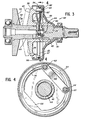
- a CVT pulley, constructed according to this invention is illustrated in Fig. 3 and is identified with the reference character 32, it being understood that the transmission comprises a pair of pulleys, one of which may be lesser in diameter than the other but substantially of the same construction. Therefore, only one pulley will be described in detail.
- the pulley 32 comprises a pair of generally conical flanges 34 and 36 with surfaces 38 and 40 defining a generally V-shaped space therebetween.
- Pulley flange 34 is press-fit at 42 onto a shaft 44, so as to be rotatable therewith.
- the shaft 44 is connected either to a prime mover or to a drivable means depending on whether or not it is a drive shaft or a driven shaft in a CVT, as explained with reference to Figs. 1 and 2.
- Flange 36 has an axial hub 46 axially slidable on shaft 44 toward and away from flange 34 to change the spacing of the flanges 34 and 36 and the space defined therebetween.
- the hub 46 radially positions the flange 36 on the shaft 44.
- a spider 48 having a hub 50 is press-fit onto the shaft 44 at 52, so as to be drivingly connected thereto.
- the spider 48 has a generally bell shape with an axially extending generally cylindrical flange 54 extending over a portion of pulley flange 36.
- a seal 56 received in a suitable groove 57 forms an hydraulic seal between the spider 48 and the pulley flange 36 yet it permits relative axial movement of the flange 36.
- a cavity 58 is defined by the pulley flange 36 and the spider 48 which can receive hydraulic fluid to urge the flange 36 toward the flange 34, the hydraulic fluid passing through suitable passages in the shaft 44 to the cavity 58.
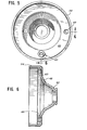
- a relatively flexible, and spring-like strap or strap-pack (if constructed of a plurality of sheet metal parts) 60 (see also Fig. 4) is positioned to pivot about axes generally parallel to the axis of the shaft 44 and is thus rotatably journaled by means of a rivet 62 to the pulley flange 36 and also by a rivet or pin 64 to the spider 48.
- a rivet 62 to the pulley flange 36 and also by a rivet or pin 64 to the spider 48.
- a depression 63 is formed in the spider 48. No special joint form is required because the joint need only permit slight rotation of the strap which occurs when there is an axial position change of the pulley flange, permitted by the flexing of the strap.
- the rivet 64 is received in a boss 65 secured (as illustrated in Figs.
- the strap which must flex axially, provides a positive drive between the spider 48 (and thus the shaft 44) and the pulley flange 36 while permitting axial movement of the pulley flange 36 toward and away from the pulley flange 34 and relative to the shaft 44.
- the strap or strap-pack thus must flex in transmitting engine torque to the pulley but does not buckle in its power transmission.
- the strap or the individual straps which constitute the strap-pack can be produced by stamping them from sheet metal. This arrangement described results in an inexpensive drive mechanism with many fewer problems than the conventional, expensive, key-keyway or ball-spline pulley flange-shaft drives.
- a counter-weight portion of the flange identified at 66, can be provided.
- multiple straps or packs of straps can be used if--desired and the number of straps in a pack can be adjusted depending on the torque capacity of the pulley.
- the particular location is chosen to provide a dynamically balanced arrangement.
- strap and strap-pack can mean one or more individual straps or an assembly of a plurality of straps, each of which is flexible to permit the flange movement desired.
- the subject invention provides a relatively inexpensive driving arrangement, avoiding the necessity for expensive machining of parts and avoiding the lubrication problems which can occur in conventional CVT drive arrangements.
Landscapes
- Engineering & Computer Science (AREA)
- General Engineering & Computer Science (AREA)
- Mechanical Engineering (AREA)
- Transmissions By Endless Flexible Members (AREA)
- Pulleys (AREA)
Applications Claiming Priority (2)
| Application Number | Priority Date | Filing Date | Title |
|---|---|---|---|
| US650022 | 1984-09-13 | ||
| US06/650,022 US4617004A (en) | 1984-09-13 | 1984-09-13 | Pulley strap drive |
Publications (2)
| Publication Number | Publication Date |
|---|---|
| EP0176256A1 true EP0176256A1 (fr) | 1986-04-02 |
| EP0176256B1 EP0176256B1 (fr) | 1988-11-09 |
Family
ID=24607150
Family Applications (1)
| Application Number | Title | Priority Date | Filing Date |
|---|---|---|---|
| EP85306069A Expired EP0176256B1 (fr) | 1984-09-13 | 1985-08-27 | Poulie variable pour courroie trapézoidale |
Country Status (8)
| Country | Link |
|---|---|
| US (1) | US4617004A (fr) |
| EP (1) | EP0176256B1 (fr) |
| JP (1) | JPS6174971A (fr) |
| KR (1) | KR860002673A (fr) |
| AU (1) | AU4653185A (fr) |
| BR (1) | BR8504401A (fr) |
| CA (1) | CA1243223A (fr) |
| DE (1) | DE3566146D1 (fr) |
Cited By (2)
| Publication number | Priority date | Publication date | Assignee | Title |
|---|---|---|---|---|
| EP0323035A1 (fr) * | 1987-12-28 | 1989-07-05 | Borg-Warner Automotive, Inc. | Transmission à courroie avec butée de sécurité contre couple de rotation inversé |
| EP0202801B1 (fr) * | 1985-05-16 | 1989-07-26 | Borg-Warner Corporation | Dispositif d'entraînement à poulie variable |
Families Citing this family (16)
| Publication number | Priority date | Publication date | Assignee | Title |
|---|---|---|---|---|
| DE3816357C1 (fr) * | 1988-05-13 | 1989-05-24 | Ford-Werke Ag, 5000 Koeln, De | |
| NL8900674A (nl) * | 1989-03-20 | 1990-10-16 | Doornes Transmissie Bv | Poelie. |
| US5407394A (en) * | 1993-05-05 | 1995-04-18 | Borg-Warner Automotive, Inc. | Guide for an adjustable pulley in a continuously variable transmission |
| JP3523114B2 (ja) * | 1999-02-25 | 2004-04-26 | 日産自動車株式会社 | 無段変速機用プーリの製造方法 |
| FR2792987A1 (fr) * | 1999-04-28 | 2000-11-03 | Gilbert Anssens | Variateur a flasques s'interpenetrant a haut rendement de rapports |
| US7500543B2 (en) * | 2000-01-24 | 2009-03-10 | Doran Paul J | Sheave with taper lock coupler |
| US6758111B2 (en) | 2001-01-26 | 2004-07-06 | Richard T. Buonauro | Continuously variable transmission |
| US20050049598A1 (en) * | 2003-08-29 | 2005-03-03 | West Hugh S. | Suture pulley for use with graft tensioning device |
| US20060058127A1 (en) * | 2004-08-24 | 2006-03-16 | Luk Lamellen Und Kupplungsbau Beteiligungs Kg | Belt-driven conical-pulley transmission, method for producing it, and motor vehicle having such a transmission |
| DE102005021866B4 (de) * | 2005-05-11 | 2016-01-14 | Zf Friedrichshafen Ag | Druckzuführung bei einem stufenlos verstellbaren Automatgetriebe, insbesondere einem Umschlingungsgetriebe |
| US8012050B2 (en) * | 2007-01-24 | 2011-09-06 | Bombardier Recreational Products Inc. | Snowmobile with improved drive train |
| JP4453740B2 (ja) * | 2007-10-25 | 2010-04-21 | トヨタ自動車株式会社 | ベルト式無段変速機のシャフト、無段変速機用固定側シーブ、その製造方法及び無段変速機 |
| JP2009224564A (ja) | 2008-03-17 | 2009-10-01 | Panasonic Corp | 配線基板とそれを用いた電子機器とそれらの誤接続検出装置 |
| US8998755B2 (en) | 2009-09-15 | 2015-04-07 | Consortium de Recherche BRP—Universite de Sherbrooke S.E.N.C. | Vehicle powertrain having a hydraulic continuously variable transmission |
| US10473195B2 (en) * | 2017-06-06 | 2019-11-12 | GM Global Technology Operations LLC | Continuously-variable transmission |
| CN111806123B (zh) * | 2020-06-05 | 2022-04-26 | 重庆电子工程职业学院 | 一种数学教学绘图装置 |
Citations (5)
| Publication number | Priority date | Publication date | Assignee | Title |
|---|---|---|---|---|
| US3393572A (en) * | 1965-03-26 | 1968-07-23 | Westerasmaskiner Ab | Variable pulley |
| US3868862A (en) * | 1973-05-14 | 1975-03-04 | Georges Henri Bessette | Expansible pulley with speed and torque responsive means |
| US3888130A (en) * | 1973-11-13 | 1975-06-10 | Leon Blanchette | Rotation responsive variable diameter pulley |
| US4010654A (en) * | 1974-12-14 | 1977-03-08 | Luk Lamellen Und Kupplungsbau Gmbh | Variable pulley part for a drive acting through a tension medium strand, such as a V-belt |
| US4386920A (en) * | 1977-09-08 | 1983-06-07 | Luk Lamellen Und Kupplungsbau Gmbh | Cone pulley |
Family Cites Families (5)
| Publication number | Priority date | Publication date | Assignee | Title |
|---|---|---|---|---|
| US1124966A (en) * | 1913-11-12 | 1915-01-12 | Edward P Stack | Coupling-link for engines. |
| US2273478A (en) * | 1939-01-18 | 1942-02-17 | Eric Locke | Variable speed device |
| BE788905A (fr) * | 1971-09-17 | 1973-03-15 | Metropolitan Tool & Prod | Perfectionnements relatifs aux tambours devideurs de cable |
| US4019345A (en) * | 1975-05-12 | 1977-04-26 | Kanto Special Steel Works, Ltd. | Flexible coupling for rotating shafts |
| US4365964A (en) * | 1980-10-29 | 1982-12-28 | Reliance Electric Company | Combination coupling and sheave |
-
1984
- 1984-09-13 US US06/650,022 patent/US4617004A/en not_active Expired - Fee Related
-
1985
- 1985-08-16 CA CA000488859A patent/CA1243223A/fr not_active Expired
- 1985-08-22 AU AU46531/85A patent/AU4653185A/en not_active Abandoned
- 1985-08-27 EP EP85306069A patent/EP0176256B1/fr not_active Expired
- 1985-08-27 DE DE8585306069T patent/DE3566146D1/de not_active Expired
- 1985-09-12 KR KR1019850006659A patent/KR860002673A/ko not_active Ceased
- 1985-09-12 BR BR8504401A patent/BR8504401A/pt unknown
- 1985-09-13 JP JP60203200A patent/JPS6174971A/ja active Pending
Patent Citations (5)
| Publication number | Priority date | Publication date | Assignee | Title |
|---|---|---|---|---|
| US3393572A (en) * | 1965-03-26 | 1968-07-23 | Westerasmaskiner Ab | Variable pulley |
| US3868862A (en) * | 1973-05-14 | 1975-03-04 | Georges Henri Bessette | Expansible pulley with speed and torque responsive means |
| US3888130A (en) * | 1973-11-13 | 1975-06-10 | Leon Blanchette | Rotation responsive variable diameter pulley |
| US4010654A (en) * | 1974-12-14 | 1977-03-08 | Luk Lamellen Und Kupplungsbau Gmbh | Variable pulley part for a drive acting through a tension medium strand, such as a V-belt |
| US4386920A (en) * | 1977-09-08 | 1983-06-07 | Luk Lamellen Und Kupplungsbau Gmbh | Cone pulley |
Cited By (2)
| Publication number | Priority date | Publication date | Assignee | Title |
|---|---|---|---|---|
| EP0202801B1 (fr) * | 1985-05-16 | 1989-07-26 | Borg-Warner Corporation | Dispositif d'entraînement à poulie variable |
| EP0323035A1 (fr) * | 1987-12-28 | 1989-07-05 | Borg-Warner Automotive, Inc. | Transmission à courroie avec butée de sécurité contre couple de rotation inversé |
Also Published As
| Publication number | Publication date |
|---|---|
| BR8504401A (pt) | 1986-07-08 |
| AU4653185A (en) | 1986-03-20 |
| KR860002673A (ko) | 1986-04-28 |
| CA1243223A (fr) | 1988-10-18 |
| DE3566146D1 (de) | 1988-12-15 |
| EP0176256B1 (fr) | 1988-11-09 |
| JPS6174971A (ja) | 1986-04-17 |
| US4617004A (en) | 1986-10-14 |
Similar Documents
| Publication | Publication Date | Title |
|---|---|---|
| US4617004A (en) | Pulley strap drive | |
| US4467670A (en) | Belt drive continuously-variable speed automatic transmission | |
| EP1234127B1 (fr) | Poulie de transmission variable de maniere continue | |
| US4740191A (en) | Power transmission system | |
| US4291790A (en) | Torque converter clutch and vibration damper | |
| CA1222399A (fr) | Poulie variatrice de vitesse par coulissement sur arbre cannele modifie pour entrainement a courroie | |
| US6213907B1 (en) | Co-axial single mode geared neutral traction transmission | |
| US4858492A (en) | Power transmission system | |
| GB2154678A (en) | Continuously variable transmission | |
| US4005609A (en) | Automatic variable speed transmission | |
| US4692130A (en) | Load block for chain-belt | |
| JPH06341500A (ja) | 無段変速装置 | |
| US4403976A (en) | Clutch for belt drive | |
| CA1067724A (fr) | Transmission motrice | |
| EP0164344B1 (fr) | Transmission variable en continu a deux plages | |
| EP0323035B1 (fr) | Transmission à courroie avec butée de sécurité contre couple de rotation inversé | |
| US4652250A (en) | Variable speed ratio drive | |
| EP0937911B1 (fr) | Transmission à changement de vitesses continue | |
| CA1255122A (fr) | Entrainement par poulie a couple variable | |
| WO1984001416A1 (fr) | Transmission variable et reversible | |
| EP0402177A2 (fr) | Dispositif de changement de vitesses | |
| US6863638B1 (en) | Drive ring CVT coupler | |
| KR0174168B1 (ko) | 무단 변속장치 | |
| JPH06264983A (ja) | ベルト式無段変速機 | |
| KR19980048325A (ko) | 벨트식 무단변속기 |
Legal Events
| Date | Code | Title | Description |
|---|---|---|---|
| PUAI | Public reference made under article 153(3) epc to a published international application that has entered the european phase |
Free format text: ORIGINAL CODE: 0009012 |
|
| AK | Designated contracting states |
Kind code of ref document: A1 Designated state(s): DE FR GB IT SE |
|
| 17P | Request for examination filed |
Effective date: 19860423 |
|
| 17Q | First examination report despatched |
Effective date: 19870721 |
|
| GRAA | (expected) grant |
Free format text: ORIGINAL CODE: 0009210 |
|
| AK | Designated contracting states |
Kind code of ref document: B1 Designated state(s): DE FR GB IT SE |
|
| PG25 | Lapsed in a contracting state [announced via postgrant information from national office to epo] |
Ref country code: SE Effective date: 19881109 |
|
| ITF | It: translation for a ep patent filed | ||
| REF | Corresponds to: |
Ref document number: 3566146 Country of ref document: DE Date of ref document: 19881215 |
|
| ET | Fr: translation filed | ||
| PG25 | Lapsed in a contracting state [announced via postgrant information from national office to epo] |
Ref country code: GB Effective date: 19890827 |
|
| PLBE | No opposition filed within time limit |
Free format text: ORIGINAL CODE: 0009261 |
|
| STAA | Information on the status of an ep patent application or granted ep patent |
Free format text: STATUS: NO OPPOSITION FILED WITHIN TIME LIMIT |
|
| 26N | No opposition filed | ||
| GBPC | Gb: european patent ceased through non-payment of renewal fee | ||
| PGFP | Annual fee paid to national office [announced via postgrant information from national office to epo] |
Ref country code: FR Payment date: 19920807 Year of fee payment: 8 |
|
| PGFP | Annual fee paid to national office [announced via postgrant information from national office to epo] |
Ref country code: DE Payment date: 19920828 Year of fee payment: 8 |
|
| ITTA | It: last paid annual fee | ||
| PG25 | Lapsed in a contracting state [announced via postgrant information from national office to epo] |
Ref country code: FR Effective date: 19940429 |
|
| PG25 | Lapsed in a contracting state [announced via postgrant information from national office to epo] |
Ref country code: DE Effective date: 19940503 |
|
| REG | Reference to a national code |
Ref country code: FR Ref legal event code: ST |