EP0176582B1 - Kraftfahrzeugleuchte und mit dieser versehene lampeneinheit für kraftfahrzeuge - Google Patents
Kraftfahrzeugleuchte und mit dieser versehene lampeneinheit für kraftfahrzeuge Download PDFInfo
- Publication number
- EP0176582B1 EP0176582B1 EP85902019A EP85902019A EP0176582B1 EP 0176582 B1 EP0176582 B1 EP 0176582B1 EP 85902019 A EP85902019 A EP 85902019A EP 85902019 A EP85902019 A EP 85902019A EP 0176582 B1 EP0176582 B1 EP 0176582B1
- Authority
- EP
- European Patent Office
- Prior art keywords
- bulb
- transparent glass
- lamp
- light rays
- exterior
- Prior art date
- Legal status (The legal status is an assumption and is not a legal conclusion. Google has not performed a legal analysis and makes no representation as to the accuracy of the status listed.)
- Expired
Links
- 239000011521 glass Substances 0.000 claims abstract description 67
- 239000000463 material Substances 0.000 claims description 10
- 230000003287 optical effect Effects 0.000 claims description 10
- 229920003023 plastic Polymers 0.000 claims description 10
- 239000004973 liquid crystal related substance Substances 0.000 claims description 9
- 230000011514 reflex Effects 0.000 claims description 6
- 239000007787 solid Substances 0.000 claims description 5
- 238000009877 rendering Methods 0.000 description 5
- 239000003086 colorant Substances 0.000 description 1
- 238000007496 glass forming Methods 0.000 description 1
- 238000005286 illumination Methods 0.000 description 1
- 230000002093 peripheral effect Effects 0.000 description 1
- 239000002966 varnish Substances 0.000 description 1
Images
Classifications
-
- F—MECHANICAL ENGINEERING; LIGHTING; HEATING; WEAPONS; BLASTING
- F21—LIGHTING
- F21S—NON-PORTABLE LIGHTING DEVICES; SYSTEMS THEREOF; VEHICLE LIGHTING DEVICES SPECIALLY ADAPTED FOR VEHICLE EXTERIORS
- F21S43/00—Signalling devices specially adapted for vehicle exteriors, e.g. brake lamps, direction indicator lights or reversing lights
- F21S43/20—Signalling devices specially adapted for vehicle exteriors, e.g. brake lamps, direction indicator lights or reversing lights characterised by refractors, transparent cover plates, light guides or filters
- F21S43/255—Filters
Definitions
- the present invention relates to motor vehicle lamps.
- Two conventional types of lamps are generally used in motor vehicles.
- the lamp includes a body, a bulb within the body and a transparent glass with a prismatic internal surface which receives light rays emitted by the bulb and focuses them outwardly into a beam having predetermined characteristics.
- the internal surface of the glass is not prismatic and the lamp includes a reflector surrounding the bulb for reflecting light rays emitted by the bulb and focusing them outwardly into a beam having predetermined characteristics.
- the present invention relates to both the above indicated types of motor vehicle lamps.
- the present invention relates to a motor vehicle lamp, comprising
- a motor vehicle lamp of the above type is known from DE-B-1259747.
- the lamp further includes an elliptical reflector surrounding the bulb, the center of the bulb and the central aperture of the internal reflective wall being located at the two focuses of such elliptical reflector, respectively.
- the lamp When the lamp is lit, light rays emitted by the bulb are first reflected by the elliptical reflector which directs the reflected rays through the central aperture of the internal reflective wall towards the transparent glass of the lamp. The latter focuses the received light rays outwardly into a beam having predetermined characteristics.
- the emitted light rays are coloured, even if the transparent glass is colourless.
- the use of an elliptical reflector insures that all light rays reflected by said reflector towards the outer transparent glass all across a single point, which is one of the focuses of the elliptical reflector.
- the central aperture at which the coloured filter is located can be very small. Therefore, when the bulb is off and the lamp is illuminated from the exterior, for example by sunlight or the lamps of another vehicle, the coloured filter is not visible. As a matter of fact, only a very small portion of the light rays coming from the exterior arrives exactly at the above mentioned small central aperture, wherein the filter is located.
- this known lamp solves the problem of allowing the emission of a coloured light beam even with a colourless transparent glass and rendering at the same time the inner coloured filter invisible when the bulb is off and the lamp is illuminated from the exterior.
- this known solution does not always prove to be satisfactory from the point of view of the lamp efficiency, due to the various changes in direction imparted to the light rays coming from the bulb and directed to the exterior.
- the object of the present invention is to provide a lamp which solves the problem of preventing the coloured filter within the lamp body from being visible from the exterior when the bulb is off and the lamp is illuminated from the exterior, and at the same time has a relatively simple and cheap structure.
- the present invention provides a motor vehicle lamp of the above indicated type, characterised by the combination of the following features:
- the central aperture of the internal reflective wall has a size sufficiently great to allow the whole internal surface of the transparent glass to be directly illuminated by the bulb when the latter is lit. This gives to the lamp a greater efficiency with respect to that of the prior art.
- the provision of diffusing lenses both on the internal surface of the transparent glass and on the internal reflective wall ensures that the light rays coming from the exterior are scattered in all directions within the lamp body and then again reflected in all direrctions by the internal reflective wall, thus preventing the coloured filter from being visible from the exterior. Therefore, a lamp of great efficiency and a simple structure is obtained while solving at the same time the problem of rendering the coloured filter invisible from outside.
- the present invention relates to a motor vehicle lamp, comprising
- a motor vehicle lamp of the above indicated type is known from FR-A-2476798.
- light rays emitted from the bulb are reflected by the reflector into a beam of predetermined characteristics.
- the use of a coloured filter allows the emission of a coloured beam even with a colourless transparent glass.
- the coloured filter is not visible since it is covered by an opaque cover.
- This cover has passages for the light rays emitted by the bulb, while the inner surface of the transparent glass has diffusing lenses designed to render minimum the quantity of light rays coming from the exterior which reach the surface of the coloured filter.
- the problem of rendering the coloured filter invisible from the outside is solved.
- the provision of the above mentioned opaque cover is relatively complicated and costly.
- the present invention reaches the above indicated object by providing a motor vehicle lamp of this second known type, characterised in that the lamp further includes a conical reflective wall enveloping said reflector and in that said reflector has a prismatic surface for reflecting light rays from the bulb to the exterior and for refracting light rays coming from the exterior of the lamp, with the exception of light rays coming from the exterior in a direction substantially parallel to the optical axis of the lamp, onto the internal reflective wall.
- the prismatic surface of the reflector is shaped so as to prevent the passage of light parallel to the optical axis of the lamp, the colour of the reflector is not visible in this direction. From all other directions, however, the colour is visible since the reflector then becomes a refractor.
- the emitted beam is relatively narrow about the optical axis and it is impossible for the colour of the conical, reflective wall to alter the characteristics of the beam.
- this observation is effected only in random directions different from that of the optical axis of the lamp.
- the diffusing lenses on the transparent glass scatter in all directions within the lamp body the light rays coming from the exterior, the scattered rays being then reflected in all directions by the prismatic reflector, thus rendering the coloured filter invisible from the outside.
- the invention also provides a light unit for motor vehicles, characterised in that it includes several lamps as specified above, having the body and the transparent glass in common.
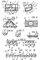
- a motor vehicle lamp generally indicated 1, comprises a body 2, for example of plastic material, a bulb 3 located within the body 2, and a transparent glass 4 also of plastic material and has, in known manner, a prismatic internal surface 5 for receiving light rays emitted by the bulb 3 and focusing them outwardly into a beam having predetermined characteristics.
- the body 2 of the lamp has, on its side opposite the transparent glass 4, a cover 6 with an aperture 7 for allowing illumination of the vehicle luggage compartment.
- a bulb holder, indicated 8, may be fixed to the body 2 as in the example of Fig. 1, or to the cover 6 as in the example of Fig. 2.
- the lamp illustrated in Fig. 2 has exactly the same structure as the light of Fig. 1 and differs therefrom solely in the shape of its various components.
- the two lamps illustrated in Fig. 1 and 2 may form part of a single rear light unit for motor vehicles, in which the lamp of Fig. 1 corresponds, for example, to the tail light of the vehicle and the lamp of Fig. 2 serves as a direction indicator.
- the same light unit may have a reversing light with a structure similar to those illustrated in Fig. 1 and 2.
- the transparent glass of the various lamps is constituted by a single element of plastic material, which has a prismatic surface 4 on its inner face in correspondence with each lamp in order to form a beam of predetermined characteristics.
- This prismatic surface formed on the inner face of the transparent glass in correspondence with each lamp has, in known manner, a central zone of refracting prisms 9 and a peripheral zone of totally reflecting prisms 10.
- a coloured filter 11 for example of glass or plastic material.
- the coloured filter 11 may be flat as illustrated in Fig. 1 and 2 or in the form of cap.
- the body 2 of the lamp includes a wall 12 located between the bulb 3 and the transparent glass 4.
- the wall 12 has an aperture 13a for allowing the passage of light from the bulb 3 which is coloured by the filter 11 and is directly incident on the inner surface of the transparent glass 4.
- the light rays outside the solid angle A through which the transparent glass 4 is visible from the centre of the bulb 3 do not pass through the aperture 13a.
- the use of the coloured filter 11 allows the use of a colourless transparent glass 4 even when the light emitted by the lamp must have a particular colour, for example red or yellow.
- those surface portions of the refracting prisms 9 which are not perpendicular to the general plane of the transparent glass 4 are shaped so as to define a series of diffusing lenses 13.
- the periopheral zone of the prismatic surface 5 includes flat zones 14 interposed between the totally reflecting prisms 10 and shaped so as to define a plurality of diffusing lenses 15 (see Fig. 6).
- Fig. 4 illustrates, by way of example, a frontal view of the internal surface of the transparent glass 4 with reference to the case in which the prisms 10 are disposed in concentric rings. Naturally, all the prisms 10 could also be arranged in the same direction, for example horizontally or vertically.
- the wall 16 is essentially in the form of a reflex reflector. It has one surface facing in the opposite direction from the transparent glass 4, which is constituted by a prismatic surface 17 comprising a series of trihedral prisms 18 with right vertices.
- the wall 17 has a series of diffusing lenses 19 on its surface facing the transparent glass 4. Consequently, the element 17 behaves as an imperfect reflex reflector. This means that it reflects light rays from the exterior of the lamp which are incident on its surface facing the transparent glass 4 in the opposite direction from which they come but with a certain degree of scattering of the light, as will be explained in detail below.
- the diffusing lenses 19 may be cylindrical or spherical lenses.
- the reflective wall 17 is shown in the appended drawings as a flat element, this wall could also be concave, for example conical, as will be explained with reference to the embodiment of Fig. 3.
- Fig. 5 relates to an embodiment in which the reflective wall 17 is constituted by an element of plastic material intended to be fixed to the wall 12 of the lamp body.
- the element 17 is formed as a layer of shiny or metallised coloured varnish (with microprisms in the form of pyramids with right vertices). It is also possible to mould the wall 12 of the lamp body from a coloured plastic material so that the wall can act as a reflective element. A further possibility is to provide for the use of a sheet of transparent plastic material of the colour which it is desired to impart to the transparent glass when the bulb is off and having a prismatic surface (with pyramidal prisms with rightvertices) made on its rear face by coining.
- a reflective screen for reflecting some of the light directed to the rear part of the lamp towards the transparent glass 4 is indicated 20.
- the coloured filter 11 is not visible from the exterior since the light (for example sunlight) which enters the lamp is reflected from the element 17 and scattered over the entire surface of the transparent glass.
- the light from the exterior which is incident on the coloured filter 11 passes therethrough and is dispersed in the rear part of the lamp.
- Fig. 5 light rays 21 are shown, by way of reference, which are directed parallel to the optical axis of the lamp. In passing through the transparent glass 4, the rays 21 are scattered by the diffusing lenses 13 and 15 (see Fig. 6 and 7). In Fig. 5 the light rays diffused respectively by the lenses 15 and the lenses 13 are indicated 22 and 23.
- a light ray 24 which is incident on the reflective wall 17 is reflected by the prisms on the rear surface of this wall and then scattered by the lenses 19 into a series of rays 25.
- the light rays reflected by the wall 17 are indicated 26. As illustrated, these light rays are scattered in various directions towards the transparent glass 4. Hence, the rays can be reflected by the wall 17 over the entire surface of the glass 4.
- the transparent glass although being colourless, takes on the colour of the reflecting elementA. It is thus possible to make the transparent glass assume, for example, the colour of the bodywork part (or bumper) adjacent thereto.
- the lamp has a liquid crystal element 27 in correspondence with the reflective wall 17, which can be switched between two operating states in which the liquid crystals are substantially transparent and substantially opaque, respectively.
- the electrical signal for switching the liquid crystals from the transparent state to the opaque state is generated at the moment when the lamp bulb is lit.
- the light coming from the exterior for example, from the headlights of a following motor vehicle
- the element 17 because the light is incident on the opaque liquid crystals
- the presence of the liquid crystal element 27 allows the reflective wall 17 to be made even with a strong colour since the disadvantage mentioned above is completely eliminated.
- the elements 17 and 27 may be formed from one coloured reflective film including a layer of liquid crystals.
- the film can be cut to the desired shape and may be flat or conical.
- a transparent glass may be formed in one colour or so as to include different zones of desired colours in correspondence with the various lamps.
- the light unit further includes a reflex reflector of the type illustrated in Fig. 7, having a dark, almost black apearance in sunlight.
- This reflex reflector is constituted by an element 28 moulded from plastic material of a red colour and fixed to a wall 29 having a black surface 30.
- One part of the internal surface of the reflector 28 has conventional prisms 31, while the remaining part is constituted by a series of flat surfaces 32 parallel to the external surface and distributed on horizontal, vertical or inclined lines.
- Fig. 3 illustrates a second embodiment of the lamp according to the present invention, in which the transparent glass 4 has a surface with diffusing lenses 33 while the reflective wall 17 is conical and surrounds the bulb 3.
- the light from the bulb is focused into a beam of predetermined characteristics by a reflector 35 of transparent plastic material having a prismatic surface 36.
- the light from the exterior which enters the lamp is refracted (with the exception of that directed parallel to the optical axis of the lamp) onto the reflective element 17, which operates in a similar manner ot that described with reference to Fig. 5.
- the prismatic surface of the reflector 35 is shaped so as to prevent the passage of light parallel to the optical axis of the lamp, however, so that the colour of the element 17 is not visible in this direction. From all other directions, however, the colour is visible since, as already mentioned, the reflector 35 then becomes a refractor. Hence, in the case of the embodiment of Fig. 3, it is not necessary to provide a liquid crystal element.
- the emitted beam is relatively narrow about the optical axis and it is impossible for the colour of the element 17 to alter in the characteristics of this beam.
- this observation is effected only in random directions different from that of the optical axis of the lamp.
Landscapes
- Engineering & Computer Science (AREA)
- General Engineering & Computer Science (AREA)
- Lighting Device Outwards From Vehicle And Optical Signal (AREA)
- Non-Portable Lighting Devices Or Systems Thereof (AREA)
Claims (5)
Applications Claiming Priority (2)
| Application Number | Priority Date | Filing Date | Title |
|---|---|---|---|
| IT6738484 | 1984-04-16 | ||
| IT8467384A IT1179912B (it) | 1984-04-16 | 1984-04-16 | Fanale per autoveicoli e gruppo ottico per autoveicoli includente tale fanale |
Publications (2)
| Publication Number | Publication Date |
|---|---|
| EP0176582A1 EP0176582A1 (de) | 1986-04-09 |
| EP0176582B1 true EP0176582B1 (de) | 1988-08-24 |
Family
ID=11301942
Family Applications (1)
| Application Number | Title | Priority Date | Filing Date |
|---|---|---|---|
| EP85902019A Expired EP0176582B1 (de) | 1984-04-16 | 1985-04-15 | Kraftfahrzeugleuchte und mit dieser versehene lampeneinheit für kraftfahrzeuge |
Country Status (6)
| Country | Link |
|---|---|
| US (1) | US4630184A (de) |
| EP (1) | EP0176582B1 (de) |
| BR (1) | BR8506702A (de) |
| DE (1) | DE3564615D1 (de) |
| IT (1) | IT1179912B (de) |
| WO (1) | WO1985004944A1 (de) |
Families Citing this family (16)
| Publication number | Priority date | Publication date | Assignee | Title |
|---|---|---|---|---|
| IT1219177B (it) * | 1988-04-05 | 1990-05-03 | Fiat Auto Spa | Fanale per autoveicoli e gruppo ottico per autoveicoli includente tale fanale |
| US4905125A (en) * | 1988-08-25 | 1990-02-27 | George Stefan | Anti reflex lamp |
| IT1223926B (it) * | 1988-11-22 | 1990-09-29 | Carello Spa | Procedimento per la produzione di fanali per veicoli |
| US5128848A (en) * | 1989-03-31 | 1992-07-07 | W.C. Heraeus Gmbh | Operating light |
| US4994947A (en) * | 1989-11-20 | 1991-02-19 | Ford Motor Company | Reflector and lighting fixture comprising same |
| WO1991011654A1 (fr) * | 1990-01-30 | 1991-08-08 | Nauchno-Proizvodstvennoe Obiedinenie Po Avtoelektronike I Avtotraktornomu Elektrooborudovaniju | Projecteur |
| US5954427A (en) * | 1997-11-05 | 1999-09-21 | Ford Motor Company | Automotive tail lamp with large rake angle |
| US6612728B2 (en) * | 2000-07-07 | 2003-09-02 | Truck-Lite Co., Inc. | Marker lamp with picture frame optics |
| JP4162935B2 (ja) * | 2002-07-04 | 2008-10-08 | 株式会社小糸製作所 | 車両用灯具 |
| CN101886765A (zh) * | 2010-07-26 | 2010-11-17 | 鸿富锦精密工业(深圳)有限公司 | Led面光源装置 |
| US9052497B2 (en) | 2011-03-10 | 2015-06-09 | King Abdulaziz City For Science And Technology | Computing imaging data using intensity correlation interferometry |
| US9099214B2 (en) * | 2011-04-19 | 2015-08-04 | King Abdulaziz City For Science And Technology | Controlling microparticles through a light field having controllable intensity and periodicity of maxima thereof |
| US20130265791A1 (en) | 2012-04-10 | 2013-10-10 | Ford Global Technologies, Llc | Vehicle light assembly with photon recycling |
| WO2013161164A1 (ja) * | 2012-04-27 | 2013-10-31 | ソニー株式会社 | 電球型光源装置及び透光性カバー |
| WO2016014785A1 (en) * | 2014-07-23 | 2016-01-28 | Myotek Pacific Corp. | Fog lamp lens and assembly |
| US20230167958A9 (en) * | 2020-11-17 | 2023-06-01 | Tan De Tech Co., Ltd. | Light guide structure |
Family Cites Families (13)
| Publication number | Priority date | Publication date | Assignee | Title |
|---|---|---|---|---|
| FR1014924A (fr) * | 1950-03-22 | 1952-08-25 | Pyb & Pharos Ets | Nouveau dispositif d'éclairage et de signalisation |
| US3264769A (en) * | 1960-12-07 | 1966-08-09 | George K C Hardesty | Illuminated fixed indicia indicating device |
| DE1259747B (de) * | 1962-07-24 | 1968-01-25 | Elastic Stop Nut Corp | Anordnung zum Verhindern von Phantomlicht in einer Signallichtanlage fuer Automobileod. dgl. |
| DE2209338A1 (de) * | 1972-02-28 | 1973-09-06 | Bosch Gmbh Robert | Beleuchtungssystem fuer kraftfahrzeuge |
| JPS4951176U (de) * | 1972-08-11 | 1974-05-07 | ||
| DE2244584A1 (de) * | 1972-09-12 | 1974-03-21 | Bosch Gmbh Robert | Kraftfahrzeugscheinwerfer |
| FR2476798A1 (fr) * | 1980-02-25 | 1981-08-28 | Cibie Projecteurs | Feu, notamment pour la signalisation de vehicules automobiles |
| DE3033096A1 (de) * | 1980-09-03 | 1982-04-08 | Robert Bosch Gmbh, 7000 Stuttgart | Vorrichtung zur gleichmaessigen ausleuchtung von schriftfeldern |
| US4441141A (en) * | 1981-03-16 | 1984-04-03 | Lo Anthony T S | Light reflector unit for a photographic camera |
| FR2503832B1 (fr) * | 1981-04-14 | 1986-04-04 | Cibie Projecteurs | Projecteur de vehicule automobile a fenetre de sortie etroite |
| US4443832A (en) * | 1981-09-29 | 1984-04-17 | Nissan Motor Co., Ltd. | Self-illuminating ornament for vehicles |
| US4450513A (en) * | 1982-01-25 | 1984-05-22 | Sterner Lighting Systems Incorporated | Lighting fixture for opposite direction reflection |
| FR2526522A1 (fr) * | 1982-05-04 | 1983-11-10 | Marchal Equip Auto | Perfectionnements aux feux pour vehicules automobiles |
-
1984
- 1984-04-16 IT IT8467384A patent/IT1179912B/it active
-
1985
- 1985-04-15 BR BR8506702A patent/BR8506702A/pt not_active IP Right Cessation
- 1985-04-15 WO PCT/EP1985/000166 patent/WO1985004944A1/en not_active Ceased
- 1985-04-15 DE DE8585902019T patent/DE3564615D1/de not_active Expired
- 1985-04-15 EP EP85902019A patent/EP0176582B1/de not_active Expired
- 1985-04-15 US US06/817,947 patent/US4630184A/en not_active Expired - Fee Related
Also Published As
| Publication number | Publication date |
|---|---|
| WO1985004944A1 (en) | 1985-11-07 |
| IT8467384A0 (it) | 1984-04-16 |
| EP0176582A1 (de) | 1986-04-09 |
| IT1179912B (it) | 1987-09-16 |
| DE3564615D1 (en) | 1988-09-29 |
| IT8467384A1 (it) | 1985-10-16 |
| BR8506702A (pt) | 1986-04-15 |
| US4630184A (en) | 1986-12-16 |
Similar Documents
| Publication | Publication Date | Title |
|---|---|---|
| EP0176582B1 (de) | Kraftfahrzeugleuchte und mit dieser versehene lampeneinheit für kraftfahrzeuge | |
| US5592578A (en) | Peripheral optical element for redirecting light from an LED | |
| US4577260A (en) | Vehicle lamp assemblies | |
| EP1005619B1 (de) | Doppelreflektierende linse | |
| JP4315516B2 (ja) | 表示ライトディスプレイ | |
| GB1598038A (en) | Reflector for lighting and/or indicator devices especially for vehicles | |
| JPH09180517A (ja) | 指示灯、特に多数の光源を備える自動車用補助停止灯 | |
| EP0649125B1 (de) | Vorrichtung zur verhinderung eines pseudo-leuchtphänomens in einer signallampe | |
| US4042818A (en) | Lamp assembly | |
| US4556928A (en) | Vehicle lamp assembly | |
| US4538216A (en) | Lighting apparatus | |
| EP0322370B1 (de) | Nebel-Heckleuchte für Kraftfahrzeuge | |
| US5556194A (en) | Vehicular lamp having glittering appearance | |
| JPS58184201A (ja) | 自動車用発光装置 | |
| EP0097449B1 (de) | Fahrzeugleuchte | |
| EP0193294A2 (de) | Signalleuchte für Fahrzeuge | |
| JPS636702A (ja) | 照明装置 | |
| JPS6288203A (ja) | 自動車用ランプ | |
| JPH036603B2 (de) | ||
| EP0886101A2 (de) | Leuchte für Kraftfahrzeuge | |
| RU2010339C1 (ru) | Секция светофора | |
| JPS5913121B2 (ja) | 車輛用灯具 | |
| JPH0314732Y2 (de) | ||
| JPS6312321B2 (de) | ||
| JPS6314802B2 (de) |
Legal Events
| Date | Code | Title | Description |
|---|---|---|---|
| PUAI | Public reference made under article 153(3) epc to a published international application that has entered the european phase |
Free format text: ORIGINAL CODE: 0009012 |
|
| AK | Designated contracting states |
Kind code of ref document: A1 Designated state(s): DE FR GB NL SE |
|
| 17P | Request for examination filed |
Effective date: 19851204 |
|
| 17Q | First examination report despatched |
Effective date: 19861223 |
|
| GRAA | (expected) grant |
Free format text: ORIGINAL CODE: 0009210 |
|
| AK | Designated contracting states |
Kind code of ref document: B1 Designated state(s): DE FR GB NL SE |
|
| REF | Corresponds to: |
Ref document number: 3564615 Country of ref document: DE Date of ref document: 19880929 |
|
| ET | Fr: translation filed | ||
| PLBE | No opposition filed within time limit |
Free format text: ORIGINAL CODE: 0009261 |
|
| STAA | Information on the status of an ep patent application or granted ep patent |
Free format text: STATUS: NO OPPOSITION FILED WITHIN TIME LIMIT |
|
| 26N | No opposition filed | ||
| PGFP | Annual fee paid to national office [announced via postgrant information from national office to epo] |
Ref country code: NL Payment date: 19930430 Year of fee payment: 9 |
|
| PGFP | Annual fee paid to national office [announced via postgrant information from national office to epo] |
Ref country code: GB Payment date: 19940316 Year of fee payment: 10 |
|
| PGFP | Annual fee paid to national office [announced via postgrant information from national office to epo] |
Ref country code: SE Payment date: 19940318 Year of fee payment: 10 |
|
| PGFP | Annual fee paid to national office [announced via postgrant information from national office to epo] |
Ref country code: DE Payment date: 19940406 Year of fee payment: 10 |
|
| PGFP | Annual fee paid to national office [announced via postgrant information from national office to epo] |
Ref country code: FR Payment date: 19940429 Year of fee payment: 10 |
|
| PG25 | Lapsed in a contracting state [announced via postgrant information from national office to epo] |
Ref country code: NL Effective date: 19941101 |
|
| NLV4 | Nl: lapsed or anulled due to non-payment of the annual fee | ||
| EAL | Se: european patent in force in sweden |
Ref document number: 85902019.0 |
|
| PG25 | Lapsed in a contracting state [announced via postgrant information from national office to epo] |
Ref country code: GB Effective date: 19950415 |
|
| PG25 | Lapsed in a contracting state [announced via postgrant information from national office to epo] |
Ref country code: SE Effective date: 19950416 |
|
| GBPC | Gb: european patent ceased through non-payment of renewal fee |
Effective date: 19950415 |
|
| PG25 | Lapsed in a contracting state [announced via postgrant information from national office to epo] |
Ref country code: FR Effective date: 19951229 |
|
| PG25 | Lapsed in a contracting state [announced via postgrant information from national office to epo] |
Ref country code: DE Effective date: 19960103 |
|
| EUG | Se: european patent has lapsed |
Ref document number: 85902019.0 |
|
| REG | Reference to a national code |
Ref country code: FR Ref legal event code: ST |