EP0176793A2 - Barre profilée de liaison - Google Patents
Barre profilée de liaison Download PDFInfo
- Publication number
- EP0176793A2 EP0176793A2 EP85111142A EP85111142A EP0176793A2 EP 0176793 A2 EP0176793 A2 EP 0176793A2 EP 85111142 A EP85111142 A EP 85111142A EP 85111142 A EP85111142 A EP 85111142A EP 0176793 A2 EP0176793 A2 EP 0176793A2
- Authority
- EP
- European Patent Office
- Prior art keywords
- profile
- connecting element
- bars
- recesses
- component
- Prior art date
- Legal status (The legal status is an assumption and is not a legal conclusion. Google has not performed a legal analysis and makes no representation as to the accuracy of the status listed.)
- Withdrawn
Links
Images


Classifications
-
- A—HUMAN NECESSITIES
- A47—FURNITURE; DOMESTIC ARTICLES OR APPLIANCES; COFFEE MILLS; SPICE MILLS; SUCTION CLEANERS IN GENERAL
- A47C—CHAIRS; SOFAS; BEDS
- A47C4/00—Foldable, collapsible or dismountable chairs
- A47C4/02—Dismountable chairs
- A47C4/028—Upholstered chairs, e.g. metal, plastic or wooden chairs
-
- A—HUMAN NECESSITIES
- A47—FURNITURE; DOMESTIC ARTICLES OR APPLIANCES; COFFEE MILLS; SPICE MILLS; SUCTION CLEANERS IN GENERAL
- A47B—TABLES; DESKS; OFFICE FURNITURE; CABINETS; DRAWERS; GENERAL DETAILS OF FURNITURE
- A47B96/00—Details of cabinets, racks or shelf units not covered by a single one of groups A47B43/00 - A47B95/00; General details of furniture
- A47B96/14—Bars, uprights, struts, or like supports, for cabinets, brackets, or the like
- A47B96/1416—Uprights receiving panels and brackets
-
- A—HUMAN NECESSITIES
- A47—FURNITURE; DOMESTIC ARTICLES OR APPLIANCES; COFFEE MILLS; SPICE MILLS; SUCTION CLEANERS IN GENERAL
- A47C—CHAIRS; SOFAS; BEDS
- A47C4/00—Foldable, collapsible or dismountable chairs
- A47C4/02—Dismountable chairs
Definitions
- the invention relates to a composite rod profile as a component for furnishing structures, in particular furniture.
- Profiles of this type usually have a substantially load-bearing function and are at the same time creative elements of the building structure, which is usually very difficult to reconcile under the condition of low material consumption and versatile application possibilities.
- the invention has for its object to provide a composite rod profile, which can be adapted to a wide variety of requirements with a simple design in terms of its strength and surface structure and can be connected to other components with high strength.
- a composite rod profile of the type mentioned in accordance with the invention in that the profile consists of at least two profile rods lying approximately parallel to one another and at least one separate connecting element used on their facing profile sides, which forms the profile rods with respect to the profile rods recesses running along the profile is set back and that the recesses are designed as receiving openings for connecting members of further components.
- the profile bars and the connecting elements can be used for the profile bars and the connecting elements, and while maintaining a uniform visual appearance for one and the same structure or for structures of a group of bar profiles with different strengths, can be achieved in that the cross sections of the profile bars and / or the connecting elements can be varied.
- a particularly high strength with slim overall cross-sections can be achieved in that the connecting element is inserted in, preferably in a common central plane, composite grooves of the respective profile bar, in particular U-shaped in cross section, and is permanently attached by gluing, gluing, toothing or the like .
- the profile bar For other areas of application, it is advantageously possible for the profile bar to have two or more lying in a central plane and / or at an angle to one another has offset composite grooves, each with at least one connecting element used or the like.
- the connecting elements can therefore be arranged in a row next to one another and / or in a star shape relative to one another.
- the profile can be produced essentially endlessly with high strength and then cut to the desired dimension by cutting to length if at least one connecting element essentially is limited in the form of strips and preferably has a thickness between the profiled bars that is at most slightly greater than the width of the, in particular rectangular, boundaries. Is composite grooves. If this thickness of the, for example flat rod-shaped, connecting element is equal to the width of the composite grooves, the connecting element can be continuously delimited in quadrangular cross-section.
- At least one profile rod and / or a connecting element is formed by a hollow profile, in particular a hollow chamber profile, so that high strength can be achieved on the one hand with low weight and on the other hand cavities for receiving supply lines, for fittings and similar are given.
- At least one profile bar and / or at least part of the connecting element consists of a wood-based material, such as plywood, plywood, solid wood or the like, the fiber course the profile bars on the one hand and the connecting elements on the other hand are selected differently and can thus be adapted to the respective requirements;
- different wood-based materials can be used for the profile bars and the connecting element or the connecting elements, for example for the solid wood profile bars and for the plywood, plywood or the like connecting element, which takes on essential supporting functions.
- the profile with otherwise the same external appearance so that the groove-like recess is undercut in cross-section, for example T-groove-shaped, dovetail-shaped or similar, and preferably its lateral boundary surfaces are formed exclusively by the profile bars and / or its base surface are formed exclusively by the connecting element.
- rails or positively locking profile grooves can be created, for example, for guiding sliding doors, sliding doors, roller shutter slats, drawers or the like.
- Both the cut-out recess which is delimited at right angles or approximately square, as well as the undercut recess, are advantageously suitable for accommodating a wide variety of other components, for example a concealed hinge, a rear wall, a side wall, a shelf, a shelf rail, of signs, of Row or place numbering, of picture plate plates, of row connecting elements, of armrests, writing plates, sound absorption elements, of busbars, cable ducts and Plug rails, from hanging plates at tables, from sealing profiles or brushes, from retractable base cabinets, from curtain rails, from flat canvas or sun protection parts, from front panels and side panels and much more.
- Both the parts inserted into the composite grooves and the parts into the cutouts can consist of a wide variety of materials, for example glass, aluminum, plastic and the like, and can also have a lattice structure, for example.
- the side surfaces of the recess are provided with form-locking members, in particular uniformly distributed over their length, preferably with abutment teeth, for example sawtooth-shaped raster teeth, so that, for example, a rubber-elastic supporting element is pre-tensioned between these side surfaces and is infinitely adjustable in height Holding intermediate floors or the like can be used.
- the bottom surface of the recess is expediently provided with form-locking members, in particular evenly distributed over its length, preferably at least one row of holes, which are at least partially directly in the connecting element and / or in a further rail rod inserted into the recess, for example one Shelf rail is provided.
- the connecting element for receiving the end of a component adjoining at an angle has a window-like plug opening, in particular only reaching as far as the side faces of the recess , of which at least two opposite boundary surfaces are designed as fastening surfaces, for example as clamping surfaces for the component braced by wedging, which is then clamped both on both sides of the connecting element to the facing profile surfaces of the profile bars, as well as to the associated opposite boundary surfaces of the insertion opening, and despite relatively small connection cross-sections, a connection of high strength is guaranteed.
- sections of the profile according to the invention form the stand supports of a four-legged chair, of which a front and a rear frame with their ends projecting laterally via a frame frame connecting them connect as a further component to the cutouts of the associated stand support profiles, these, frames also designed as flat bars expediently have a thickness which is exactly the same as the width of the recesses of the stand supports, that is to say exactly the same as the distance between the profile bars of the respective stand support.
- the ends of the rod profile according to the invention also form receiving plugs for the form-fitting arrangement of corresponding end pieces, which, depending on the requirements, can be designed for a wide variety of technical effects.
- at least one end of the profile can be provided with a further component in the form of an end piece, which has interlocking engaging plugs between the profile bars and in particular an end plate which is congruent with the end faces of the profile bars and covers the cutouts at the ends, so that a smooth surface finish of, for example, only achieved by a cut cut profile end.
- This or another trained end Component can, for example, have at least one connector for the clamp-like engagement at the end of the recesses of adjacent profiles, so that two profile sections lying parallel to one another or at a corresponding distance from one another are combined in a clamp-like manner by one or two of these components to form a dimensionally stable component can.
- the component provided with the plug or plugs can be designed in such a way that it can be secured against rotation, exchangeable, engaging in linearly adjoining profiles and arranged in a variety of other ways.
- this component may be a micro-jack, with a Leuchtkör he p for emergency lighting, or be configured as a reading lamp.
- a writing tablet can be designed to hang up a writing tablet, a tray, a writing support, a music stand, an infirmary, a knee bench, a footrest, a rotary eccentric, a card stand, a clothes rail, a bag holder, a magazine holder, a glass plate and much more.
- a particularly advantageous development of the subject matter of the invention consists in that at least one further component has a fastening element for the centered or guided engagement lying between the profile ends in at least one recess of at least one profile, preferably two fastening elements lying at an angle to one another and / or around one to the bottom surfaces of the recesses of the profiles to be connected, approximately perpendicular axis are pivotally mounted to one another.
- a fastening element for the centered or guided engagement lying between the profile ends in at least one recess of at least one profile, preferably two fastening elements lying at an angle to one another and / or around one to the bottom surfaces of the recesses of the profiles to be connected, approximately perpendicular axis are pivotally mounted to one another.
- the further component is suitable to connect two bar profiles to one another at a node, the two bar profiles being able to assume any angular position relative to one another when the two fastening members are pivotably mounted on one another.
- the further component for example when used for row seating, is advantageously also suitable as a label, for example for the seat number or the row of chairs, for example the end plate for the seat number and the outer surface of a plug for the row number.
- At least one further component can be designed as a stand, in particular as a floor screw bracket, floor glider, sliding curve, roller, height-adjustable leveling foot or the like, so that there is a gentle closure of the lower end of the bar profile.
- the profile according to the invention is advantageously suitable as a variable construction element because the connecting element forming an intermediate piece can be dimensioned in a wide variety of ways, for example with profile bars remaining the same.
- the two recesses on the two sides of the profile are suitable for solving many technical problems that occur in furniture and interior design, for example for centering, as a stop for a second part, for contrasting coloring, etc.
- the connecting element can, for example, be painted separately from the profile bars , after which the profile bars and the connecting element are assembled to the composite profile, so that there is a simple production even when the floor area the recess has a different color than the other surfaces of the profile.
- the connecting element can also be composed of layers of different materials in a sandwich construction or formed by two spaced-apart, for example strip-shaped, individual elements which are inserted in separate profiled grooves in each profile rod and which delimit a cavity between them, in which, for example, a cable harness for electrical power connections is integrated. Due to the advantages described, the profile is particularly suitable for the manufacture of tables, folding tables, chairs, armchairs, armchair groups, cupboards, showcases, shelves, desks, typewriter tables, lecterns, beds, loungers, auditorium chairs, containers, information signs and much more, as well as in the shop. and exhibition stand construction.
- a composite rod profile according to the invention has the same, approximately H-shaped cross-sections throughout its length, its cross-sectional extent parallel to the central plane 2 passing through the H-crosspiece, as a rule, at least twice is as large as parallel to the central plane 3 perpendicular to it.
- the profile On the longitudinal surfaces lying transversely to the central plane 3, the profile is part-circular, in the exemplary embodiment shown rounded in a semicircle, while the remaining edges, in particular the boundary edges of two groove-like recesses, are sharp-edged.
- the profile is both symmetrical to the central plane 2 and symmetrical to the central plane 3, that is to say preferably axially symmetrical to a longitudinal axis which lies in both central planes.
- the profile 1 consists essentially of three separate parts which are connected in a non-detachable manner by suitable means, such as, for example, gluing after they have been finished, that is to say also after they have been coated.
- Two of these parts are of identical design and form two profile bars 4 opposite one another on both sides of the central plane 3, the cross-sectional extent of which parallel to the central plane 2 is approximately the same or slightly smaller than their cross-sectional extent parallel to the central plane 3.
- These profile bars 4 form the part-circular rounded longitudinal edge surfaces 6 of the profile. Lying symmetrically to the central plane 2, a connecting element 5 is inserted between the profiled bars 4 in the form of a flat bar with an elongated cross section.
- This connecting element 5 which advantageously passes continuously over the length of the profiled bars 4, forms a spacer between the profiled bars 4, so that between them the two mutually identical groove-shaped recesses 7 lying on both sides of the connecting element 5 continuously pass through the entire length of the profile.
- each profiled rod has on its inner surface 9 facing the other profiled rod 4, flat and parallel to the central plane 3, a compound groove 8 which is symmetrical to the central plane 2 and which is completely filled in by the engaging section of the connecting element 5 and, in the exemplary embodiment shown, in the manner of a Rectangular groove is limited, the depth of which is greater than its width.
- the connecting element 5 thus engages in each profile rod 4 to a depth which corresponds to approximately half of its cross-sectional extent parallel to the central plane 2 and is approximately one third smaller than the width of the cutouts 7.
- the side surfaces of the composite grooves 8 are parallel to the central plane 2, while their bottom surfaces are perpendicular to it.
- the transition longitudinal edges 10 between the inner surfaces 9 or the side surfaces of the recesses 7 and the outer flank surfaces 12 of the profile bars 4 are sharp-edged in cross section at right angles, as are the inner projecting corner edges of the recesses 7, which are free due to the transition between the inner surfaces 9 and the lying flank surfaces of the connecting element 5 are formed, which form the bottom surfaces 13 of the recesses 7.
- the inner surfaces 9 of the profiled bars 4 form the side surfaces 14 of the recesses 7. Following the longitudinal edges 10, the flank surfaces 12 are flat, after which they merge into the rounded longitudinal edge surfaces 6.
- the central axis of the longitudinal edge surfaces 6 is thus approximately. in the bottom surface of the associated composite groove 8.
- Die Side sections 15 of the connecting element 5, which engage in the composite grooves 8, have the same thickness in the exemplary embodiment according to FIG. 1 as the remaining connecting element 5, that is to say as its section lying between the profiled bars 4, in such a way that the associated ones - Continuously and possibly even go through the outer surfaces of the connecting element 5 over its width.
- FIGS. 2 to 14 the same reference numerals as in FIG. 1 are used for corresponding parts, but with different letter indices.
- the profile 1a according to FIG. 2 has essentially the same profile bars 4a as the profile according to FIG. 1, but the section of the connecting element 5a lying between these profile bars 4a is thicker than in the exemplary embodiment according to FIG. 1.
- the strip sections 15a of the connecting element 5a engaging in the composite grooves However, they have the same thickness as in the exemplary embodiment according to FIG. 1 and are therefore slightly reduced in thickness compared to the central section.
- their outer surfaces associated with the side surfaces of the composite grooves 8a are provided with, for example, barb-shaped or sawtooth-shaped longitudinal teeth 16, so that they engage in a claw-like manner in the side surfaces of the composite grooves 8a under pretension and this results in a very stable connection.
- the profile bars 4b of the profile 1b according to FIG. 3 are rectangular or approximately square in cross-section, all the longitudinal edges of the profile bars being rounded approximately in a quarter circle, such that the longitudinal edges 10b associated with the recesses 7b are also rounded.
- the longitudinal edge surfaces 6b of the profile bars 4b which face away from one another are formed by flat surfaces which are parallel to the central plane 3b.
- the profile bars 4c can also be designed in cross section so that the recesses 7c are expanded approximately at an acute angle to their open sides in width, since the inner surfaces 9c on each side of the connecting element 5c converge toward the latter.
- the inner surfaces 9c merge via rounded sections into outer surfaces 12c, 6c of the profiled bars: 4c, which converge in a rounded triangle shape on their sides facing away from one another.
- cross-sectionally isosceles or equilateral profile bars 4d have flat outer surfaces which are formed by the inner surfaces 9d and the flank surfaces 12d, these outer surfaces merging into one another via rounded longitudinal edges 6d, 10d.
- the profile bars 4e can also be formed according to FIG. 6 by hollow profiles which expediently have a constant wall thickness over their cross section and a continuously closed wall.
- the connecting element 5f can also be composed of several parts, the division planes of which are expediently approximately parallel to the central plane 2f. These parts can be formed by the layers of plywood or plywood, by laminates in sandwich construction or the like. Furthermore, it is conceivable that gaps are left free between at least two parts of the connecting element 5f, which pass through the length of the connecting element 5f and thus form continuous cavities over its width and length.
- FIG. 8 shows a profile 1g which has three profile bars 4g, 4'g and two connecting elements 5g, all of which lie behind one another in cross section parallel to the central plane 2g.
- the two outer profile bars 4g correspond to the profile bars described and point to them
- Inner surfaces 9g each have a composite groove 8g, while the profile rod 4'g has a cross-sectional shape that differs from the profile rods 4g, in the exemplary embodiment shown a rectangular cross section, and each has a composite groove 8'g on its mutually facing longitudinal surfaces 9'g facing the inner surfaces 9g is.
- the composite grooves 8'g have a smaller depth than the composite grooves 8g, but the cross-sectional extent of the profile bar 4'g parallel to the central plane 2g is approximately the same as that of the profile bars 4g.
- the profile 1g has two recesses 7g lying next to one another and having the same cross section on each side.
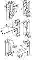
- FIG. 9 shows the attachment of a further component 25 to a profile according to the invention, in the exemplary embodiment shown on profile 1 according to FIG. 1;
- the further component 25 is, for example, a frame with a rectangular cross section made of wood or the like, the thickness of which is exactly the same as the width of the recesses 7.
- a plug-in opening 18 is introduced into the connecting element 5, the extent of which in the longitudinal direction of the profile 1 is equal to the cross-sectional height of the component 25 and the lateral boundary surfaces 19 of which lie in the plane of the respectively associated side surfaces 14 of the recesses 7, which lie on the same level with one another , so that there are continuous lateral fastening surfaces over the thickness of the profile 1 or between the flank surfaces 12.
- the component 25 is inserted from one side of the profile 1 until its end surface 20 is flush with the associated flank surfaces 12 of the profile 1.
- a flat, wedge-shaped wedge 21 is then driven into a corresponding wedge slot of the component 25 from the end face 20, which wedge is expedient at least approximately over the thickness of the profile 1 is sufficient and lies in the middle level 3.
- the component 25 is clamped uniformly against the side surfaces 14 of both cutouts 7 and against the boundary surfaces 19 of the plug-in opening 18 and thus against the connecting element 5, that is to say continuously over the entire thickness of the profile 1.
- the profile 1h according to FIG. 10 has a hollow chamber profile in the form of, for example, an extruded profile as the connecting element 5h, which is divided over the width of the connecting element 5h into a plurality of rectangularly delimited chambers that are completely closed to the outside except at the ends by partition walls.
- the chambers which are completely closed to one another between the ends of the connecting element 5h can be used for accommodating supply lines, for example electrical lines or the like.
- the profile 1i according to FIG. 11 has on the bottom surfaces 13i of both recesses 7i evenly distributed form-locking members over its length in the form of a row of holes 22 which lies in the middle of the width of the recesses 7i and is formed by holes which pass through the connecting element 5i.
- these form-locking members are not provided directly in the connecting member 5k, but are formed by a separate rail rod 23, which is inserted into the associated recess 7k.
- the rail rod 23 has, in the manner of a so-called shelf rail, elongated rectangular openings one above the other for optionally hanging support brackets on which shelf shelves can be placed.
- the crosspiece of the cross-sectionally U-shaped rail rod 23 is located so that the Support brackets with their hook-like hook-in members have space behind the rail rod 23, at a distance from the connecting element 5k, while the profile legs of the rail rod 23 rest against the side surfaces of the recess 7k and extend as far as the connecting element 5k.
- a three-track curtain rail is provided as an additional rail rod 23m, which essentially completely fills the associated recess 7m.
- the profile bars 4m in this embodiment are further apart than in most of the previously described profiles, the exposed central section of the connecting element 5m being correspondingly wider.
- FIG. 14 shows two identical profiles 1n lying parallel to one another with their flat sides, the recesses 7n of which are undercut in the manner of dovetail grooves.
- the facing boundary surfaces 9n of the profile bars 4n are provided at an obtuse angle V-shaped symmetrically to the central plane 2n.
- FIG. 14 also shows a further exemplary embodiment of a further component 26 which is intended for the end arrangement of two profiles 1n placed against one another in accordance with FIG. 14 in such a way that the two profiles 1n are fastened to one another in a clamp-like manner by this component.
- the further component 26 has a connection
- the end plate 24 is designed and arranged so that when the component 26 is inserted, it covers both end faces of the profiles 1n congruently and closes the recesses 7n at their ends.
- FIGS. 15 to 19 show further components 27 to 31 which have connecting members 38 to 42 for the guided engagement in a recess 7 of a profile 1 according to FIG. 1, which is located between the profile ends.
- the connecting members 38 to 42 essentially have in common that they fit into the recess 7 almost without play and are formed, for example, by a correspondingly dimensioned rectangular rod piece, which can be secured in the manner of a fastening member, for example by screws, relative to the connecting element 5.
- the embodiment according to FIG. 15 is a connecting piece for transverse and longitudinal profiles 1, only one of which is shown and which can be attached to this connecting piece at any point in its longitudinal direction.
- two identical connecting members are to be ver one to the bottom surfaces 13 of both binding profiles right-angled axis 48 pivotally arranged to each other, this axis 48 lies in the middle of the width of the bottom surfaces 13.
- the profiles 1 connected to one another via the component 27 can be set at an angle to one another pivoting about the axis 48.
- the connecting members 38 protrude only slightly above the flanks of the profile bars 4, so that the two interconnected profiles 1 only have the distance from one another that is required as a play. It is also conceivable to arrange the two connecting members 38 rigidly or fixably to one another at the desired angle, so that the two interconnected profiles 1 assume a precisely defined angle to one another.
- the connecting member 39 of the component 28 according to Figure 16 forms part of a tenon hinge, the hinge axis 49 is parallel to the profile 1 in the central plane 3 and within the associated recess 7, so that there is a concealed hinge, the other hinge part for the attachment of the Component to be pivoted, such as a door or the like protruding from the profile 1.
- the component 29 according to FIG. 17 is, for example, a writing surface for a chair, which is rigidly connected to the connecting element 40, which is designed similarly to the connecting element 38.
- the component 30 is designed as a floor mounting bracket, the bottom of which lies the angled limb projecting outwards beyond the profile with its underside in the plane of the lower end face of the profiled section 1 and the angled formed by the other angled limb closing member 41 is arranged completely in the associated recess 7.
- This component 30 is suitable, for example, as a panic protection for row seating, in which individual chairs are secured against slipping against the floor at greater intervals and the securing can nevertheless be easily released in an emergency.
- the pin passes through the horizontal angle leg and engages in a corresponding counter opening in the floor in such a way that it can only be disengaged by lifting the chair.
- the component 31 according to FIG. 19 is an armrest which is formed by the one, longer leg of the angular component 31, the other leg of which forms the associated connecting member 42.
- the profile 1p according to FIG. 20 has abutment teeth 50 on the side faces of one or both recesses 7p, which run through the entire length of the profile 1p.
- the recess 7p is assigned, for example, a rubber-elastic connecting member 43 which can be inserted into the recess with a prestress such that it is pressed into the abutment teeth 50 in a claw-like manner and is suitable for supporting a further component in the form of, for example, a table top 32.
- FIG. 21 shows an end piece 51, for example for a profile 1, which is not secured by engagement in the recesses 7, but rather engages directly in the connecting element 5 from the associated end face.
- the end piece 51 has a pin 52 protruding at a right angle at an end plate 24qu, for example in the form of a dowel pin, a screw pin or the like, which engages in a corresponding opening in the connecting member 5.
- Figure 22 shows a further component 33 in the form of an end piece, which has an end plate 24r and on both sides protruding over this connection members 44 in the form of plugs that two profiles 1 can be connected to one another in their longitudinal direction and the end plate 24r to each other facing end faces of both profiles covering or as a flat intermediate member.
- the connecting members 44 are adapted to a profile 1 according to FIG. 1 and are provided in alignment with one another on both sides of the end plate 24r, the connecting members 44 being able to be of different or the same length on both sides of the end plate 24r.
- FIG. 23 shows a further component 34, which, like the component 26 according to FIG. 14, is provided for connecting two parallel profiles.
- the connecting members 45 in the form of plugs adapted to the recesses 7 of the profile 1 are arranged in pairs such that the two profiles to be connected in clamp-like manner by the component 34 do not lie directly against one another but are at a predetermined distance from one another.
- the two end plates 24s are kept at a distance from one another via a connecting web 53.
- While the components 26 and 34 according to FIGS. 14 and 23 are designed such that they connect the associated profiles to one another in such a way that they are adjacent to one another in the direction of the central plane 3, the component 35 is designed such that the components connected by it Profiles 1 according to FIG. 24 lie adjacent to one another in the direction of the central plane 2.
- the component 35 engages with plug-like connecting members 46 from the lower ends of the profiles 1 in their recesses 7, the profiles 1 being able to form, for example, the legs or supports of a chair, table or the like and are at a corresponding distance from one another.
- the end plate 24t of the component 35 which extends through both profiles forms, for example, a sliding curve for the associated furniture.
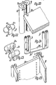
- the further component 36 according to FIG. 25 is, for example, the side walls of a retractable base cabinet, the associated edge zones of which form the connecting members 47, which fit into the cutouts 7 in the profiles 1. Immediately adjacent to the profiles 1, the side walls are connected to one another via a cross plate 54.
- FIG. 26 shows a chair 17 constructed using profiles according to the invention, the four stand supports 55, 56 of which are formed by sections of the profile 1 according to FIG. 1.
- the rear stand supports 55 are higher than the front stand supports 56 and carry a back support 58 above the seat part on a curved transverse frame 59.
- These ends 63 like the ends of the transverse frame 59 which are aligned with one another, are fastened in the two respective stand supports 55, 56 in accordance with the explanations with reference to FIG.
- the upper and lower ends of the stand supports 56 are covered with end pieces, at least one of which is used as a label carrier can be seen that its end plate 24u or the Au is ß enamide its outer plug 64 with a, for example, embossed lettering or numbering provided.
- the chair according to FIG. 27 differs from that according to FIG. 26 essentially only in that it is provided with armrests or armrests 31u, which are fastened with suitable fastening members in the ends of the cross frame 59, braced against the associated outer surfaces of the rear stand supports 55, and possibly suitable with adjacent chairs, such that only a common armrest is provided between adjacent chairs.
- the table 65 according to FIG. 28 has, for example, stand supports 66 which are made from profiles according to FIG. 8, the two outer profile webs 4g merging in the lower region into horizontal sections facing away from one another and carrying a section 67 of the connecting elements 5 projecting over their undersides, which forms the footprint of the table, for example in the form of a plastic glider.
- the table top 68 is provided in the manner of a edging with an edging which has a U-shaped profile bar 69 on the underside of the table top 68, a profile bar 70 which is angular in cross section at the top and which connects a flat strip-shaped connecting element 71 which extends from the upright angle leg of the upper profile bar 70 is overlapped on the outside, so that there is also a groove-shaped recess with a recessed bottom surface.
- the connecting element 5v can also have a star-shaped cross section and carry a profile bar 4v on each strip section 15v, in the exemplary embodiment shown five evenly distributed profile bars 4v.
- the lower ends of the profile bars 4v go in Stand arms 73 projecting radially from the connecting element 5v, each of which carries a roller 74 on the underside in the region of their free ends.
- this arrangement is provided to form a single-column swivel chair foot 72, the column of which stands in the central axis of the connecting element 5v.
- the profile 1w according to the invention can be subdivided in a simple manner into sections 75 lying at an angle to one another, the connecting element 5w being able to be formed in one piece by appropriate cutting or bending, so that even in such an embodiment very high strengths are achieved surrender.
- the sections of the profile bars 4w which adjoin one another at an angle abut at 76 at miter cut and, with their abutting end faces can also be directly connected to one another, for example by gluing.
Landscapes
- Life Sciences & Earth Sciences (AREA)
- Engineering & Computer Science (AREA)
- Wood Science & Technology (AREA)
- Mutual Connection Of Rods And Tubes (AREA)
- Connection Of Plates (AREA)
- Furniture Connections (AREA)
- Joining Of Building Structures In Genera (AREA)
- Assembled Shelves (AREA)
Applications Claiming Priority (2)
| Application Number | Priority Date | Filing Date | Title |
|---|---|---|---|
| DE19843436492 DE3436492A1 (de) | 1984-10-05 | 1984-10-05 | Verbund-stangenprofil |
| DE3436492 | 1984-10-05 |
Publications (2)
| Publication Number | Publication Date |
|---|---|
| EP0176793A2 true EP0176793A2 (fr) | 1986-04-09 |
| EP0176793A3 EP0176793A3 (fr) | 1986-09-10 |
Family
ID=6247135
Family Applications (1)
| Application Number | Title | Priority Date | Filing Date |
|---|---|---|---|
| EP85111142A Withdrawn EP0176793A3 (fr) | 1984-10-05 | 1985-09-04 | Barre profilée de liaison |
Country Status (3)
| Country | Link |
|---|---|
| US (1) | US4676469A (fr) |
| EP (1) | EP0176793A3 (fr) |
| DE (1) | DE3436492A1 (fr) |
Cited By (1)
| Publication number | Priority date | Publication date | Assignee | Title |
|---|---|---|---|---|
| US5766601A (en) * | 1990-08-08 | 1998-06-16 | University Of Massachusetts Medical Center | Cross-reactive influenza a immunization |
Families Citing this family (9)
| Publication number | Priority date | Publication date | Assignee | Title |
|---|---|---|---|---|
| US6412249B1 (en) | 1995-10-17 | 2002-07-02 | Boyer Building Products, Inc. | Wall stud |
| US6505449B1 (en) * | 2000-07-27 | 2003-01-14 | Composit Wood Specialties Ltd. | Structural element |
| US20030154660A1 (en) * | 2001-10-19 | 2003-08-21 | Michael Berkowicz | Connector for arranging modular seats in a non-linear array |
| US7017320B2 (en) * | 2002-10-02 | 2006-03-28 | Yuan-Kuan Chen | Metal tubes for guardrail |
| US6796101B2 (en) * | 2002-10-02 | 2004-09-28 | Yuan-Kuan Chen | Metal tubes for guardrail |
| US7523592B2 (en) * | 2005-05-20 | 2009-04-28 | Duracase Proprietary, Llc | Handrail assembly with panel and engaging sleeves |
| WO2011109868A1 (fr) * | 2010-03-10 | 2011-09-15 | Solid Racks Pty Limited | Système de support et console |
| WO2015190915A1 (fr) * | 2014-06-12 | 2015-12-17 | Alliance Contract Manufacturing Sdn Bhd | Ensemble support |
| US9655443B2 (en) * | 2014-07-16 | 2017-05-23 | American Glasscrafters, Inc. | Adjustable shelf support system for medicine cabinets |
Family Cites Families (22)
| Publication number | Priority date | Publication date | Assignee | Title |
|---|---|---|---|---|
| DE7120338U (de) * | 1971-09-02 | Mittermaier E | Aluminium Strangpressprofil zur Her stellung von T , Doppel T oder Kasten profilen zur Verwendung im Fahrzeug und Konstruktionsbau | |
| US919526A (en) * | 1908-07-03 | 1909-04-27 | Ralph Roy Belcher | Shelving construction. |
| US2336604A (en) * | 1940-11-05 | 1943-12-14 | Edward Walter Gordon | Detachable cantilever bracket structure |
| US3261585A (en) * | 1960-04-20 | 1966-07-19 | Victory Metal Mfg Company | Pilaster adapter |
| FI36324A (fi) * | 1964-08-11 | 1966-10-10 | Kooperativa Foerbundet | Stolpe för hyllkonstruktioner |
| US3335992A (en) * | 1965-11-23 | 1967-08-15 | Frazier Donald | Clamping brackets for a rack structure |
| DE1298253B (de) * | 1966-03-21 | 1969-06-26 | Sachau Helmuth Heinrich | Fachbodentraeger mit Klemmvorrichtung zur Hoehenverstellung an einem Hohlprofilpfosten |
| DE6948521U (de) * | 1969-12-16 | 1970-06-04 | Dieckmann Gmbh & Co Kg Erich | Aus mehreren profilen zusamengesetzte regalschiene. |
| CH507687A (de) * | 1970-05-15 | 1971-05-31 | Suter Adolf | Bauteilsatz zur Herstellung eines Anbaumöbels |
| FR2094260A5 (fr) * | 1970-06-15 | 1972-02-04 | Vincens Rene | |
| US3735548A (en) * | 1970-09-10 | 1973-05-29 | A Ferrari | Prefabricated self-supporting reinforced concrete shelving element for forming storage spaces |
| US3712015A (en) * | 1970-10-09 | 1973-01-23 | Gypsum Co | Integral stud and bracket standard for use in a wall construction |
| CH545941A (fr) * | 1971-11-23 | 1974-02-15 | ||
| SE7311226L (fr) * | 1973-08-17 | 1975-02-18 | Expo Nord Ab | |
| GB1503588A (en) * | 1975-07-03 | 1978-03-15 | Profiles & Tubes De L Est | Building frame structural elements and fixing members therefor |
| US4189459A (en) * | 1977-06-06 | 1980-02-19 | Jones Wilson M | Method of making a shelf support post |
| DE2730487A1 (de) * | 1977-07-06 | 1979-01-25 | Dustmann Dula Werk | Regalpfosten mit einhaengeschlitzen |
| DE7808705U1 (de) * | 1978-03-22 | 1978-09-14 | Dr. Heinz Kluge Nachf. Gmbh & Co, 4000 Duesseldorf | Profilstab |
| CH634625A5 (en) * | 1978-09-03 | 1983-02-15 | Ernst Koller | Profiled-bar-shaped structural element and building having profiled-bar-shaped structural elements |
| FR2470561A1 (fr) * | 1979-11-28 | 1981-06-12 | Gayet Georges | Profile en bois pour la realisation de meubles |
| DE8201879U1 (de) * | 1982-01-27 | 1982-06-16 | Wieland-Werke Ag, 7900 Ulm | Mehrteiliges, waermegedaemmtes metallprofil, insbesondere fuer fassaden od. dgl. |
| US4566231A (en) * | 1983-09-27 | 1986-01-28 | The Boeing Company | Vibration damping stiffener |
-
1984
- 1984-10-05 DE DE19843436492 patent/DE3436492A1/de not_active Withdrawn
-
1985
- 1985-09-04 EP EP85111142A patent/EP0176793A3/fr not_active Withdrawn
- 1985-09-19 US US06/777,672 patent/US4676469A/en not_active Expired - Fee Related
Cited By (1)
| Publication number | Priority date | Publication date | Assignee | Title |
|---|---|---|---|---|
| US5766601A (en) * | 1990-08-08 | 1998-06-16 | University Of Massachusetts Medical Center | Cross-reactive influenza a immunization |
Also Published As
| Publication number | Publication date |
|---|---|
| DE3436492A1 (de) | 1986-04-10 |
| EP0176793A3 (fr) | 1986-09-10 |
| US4676469A (en) | 1987-06-30 |
Similar Documents
| Publication | Publication Date | Title |
|---|---|---|
| DE3688977T2 (de) | System von trennwandplatten. | |
| DE3875822T2 (de) | Trennwand, insbesondere fuer bueros. | |
| EP0901332B1 (fr) | Systeme modulaire d'amenagement interieur | |
| DE2908153C2 (fr) | ||
| DE3200310A1 (de) | Gestell aus mehreren profilstaeben | |
| EP0176793A2 (fr) | Barre profilée de liaison | |
| DE3438364C1 (de) | Bausatz fuer individuell gestaltbare Moebelgestelle,wie Schauvitrinen,Verkaufstheken,Messemobiliar o.dgl. | |
| DE3047532A1 (de) | Regal- und schranksystem im baukastenprinzip | |
| EP0142659B1 (fr) | Eléments de construction en bois pour rayonnages, armoires | |
| DE1778336C3 (de) | Möbelsystem für den Zusammenbau von Kastenmöbeln | |
| DE2149177A1 (de) | Verbundgefuege geringen Gewichts | |
| DE3688113T2 (de) | Elementensatz fuer die einrichtung von ausstellungsraeumen, geschaeften und anderen orten. | |
| DE102021109616B4 (de) | Variables Möbelelement und modulares Möbelsystem aus mehreren Möbelelementen | |
| DE29508050U1 (de) | Verkleidungssystem | |
| EP0279418A2 (fr) | Latte profilée pour la construction d'un panneau conçu pour recevoir des articles à accrocher | |
| DE3625046A1 (de) | Profilelementesystem zum aufbau von rahmenteilen fuer theken, kabinen, kleiderstaender und dergl. | |
| DE4415037A1 (de) | Regalanordnung und/oder Schaugestell | |
| DE2438860A1 (de) | Regalfoermiges moebelstueck | |
| DE3600933A1 (de) | Zerlegbare stellwand, insbesondere fuer ausstellungen | |
| EP0784160B1 (fr) | Présentation de vente | |
| DE1941797U (de) | Nach dem baukastenprinzip aus vorgefertigten, in massen hergestellten elementen zusammengesetzter kuechenmoebelsatz. | |
| DE10300590A1 (de) | Möbelsystem mit plattenförmigen Bauelementen | |
| DE4430320C2 (de) | Möbelsystem für die Erstellung von Regalen, Schränken, Vitrinen und Tischen | |
| EP0363720A2 (fr) | Corps de meuble | |
| DE2445015A1 (de) | Einrichtungsgegenstaende |
Legal Events
| Date | Code | Title | Description |
|---|---|---|---|
| PUAI | Public reference made under article 153(3) epc to a published international application that has entered the european phase |
Free format text: ORIGINAL CODE: 0009012 |
|
| AK | Designated contracting states |
Kind code of ref document: A2 Designated state(s): AT BE DE FR GB NL |
|
| PUAL | Search report despatched |
Free format text: ORIGINAL CODE: 0009013 |
|
| AK | Designated contracting states |
Kind code of ref document: A3 Designated state(s): AT BE DE FR GB NL |
|
| 17P | Request for examination filed |
Effective date: 19860821 |
|
| 17Q | First examination report despatched |
Effective date: 19871120 |
|
| STAA | Information on the status of an ep patent application or granted ep patent |
Free format text: STATUS: THE APPLICATION IS DEEMED TO BE WITHDRAWN |
|
| 18D | Application deemed to be withdrawn |
Effective date: 19890427 |
|
| RIN1 | Information on inventor provided before grant (corrected) |
Inventor name: ROTERMUND, HERMANN Inventor name: LEIENDECKER, ARNO Inventor name: WIESMANN, HERBERT L. |