EP0176826A2 - Méthode et appareil pour la mesure de transmission spectrale à double faisceau - Google Patents
Méthode et appareil pour la mesure de transmission spectrale à double faisceau Download PDFInfo
- Publication number
- EP0176826A2 EP0176826A2 EP85111475A EP85111475A EP0176826A2 EP 0176826 A2 EP0176826 A2 EP 0176826A2 EP 85111475 A EP85111475 A EP 85111475A EP 85111475 A EP85111475 A EP 85111475A EP 0176826 A2 EP0176826 A2 EP 0176826A2
- Authority
- EP
- European Patent Office
- Prior art keywords
- sample
- photodetector
- measurement
- illumination
- directing
- Prior art date
- Legal status (The legal status is an assumption and is not a legal conclusion. Google has not performed a legal analysis and makes no representation as to the accuracy of the status listed.)
- Withdrawn
Links
Images

Classifications
-
- G—PHYSICS
- G01—MEASURING; TESTING
- G01N—INVESTIGATING OR ANALYSING MATERIALS BY DETERMINING THEIR CHEMICAL OR PHYSICAL PROPERTIES
- G01N21/00—Investigating or analysing materials by the use of optical means, i.e. using sub-millimetre waves, infrared, visible or ultraviolet light
- G01N21/17—Systems in which incident light is modified in accordance with the properties of the material investigated
- G01N21/59—Transmissivity
- G01N21/5907—Densitometers
-
- G—PHYSICS
- G01—MEASURING; TESTING
- G01J—MEASUREMENT OF INTENSITY, VELOCITY, SPECTRAL CONTENT, POLARISATION, PHASE OR PULSE CHARACTERISTICS OF INFRARED, VISIBLE OR ULTRAVIOLET LIGHT; COLORIMETRY; RADIATION PYROMETRY
- G01J1/00—Photometry, e.g. photographic exposure meter
- G01J1/10—Photometry, e.g. photographic exposure meter by comparison with reference light or electric value provisionally void
- G01J1/20—Photometry, e.g. photographic exposure meter by comparison with reference light or electric value provisionally void intensity of the measured or reference value being varied to equalise their effects at the detectors, e.g. by varying incidence angle
- G01J1/34—Photometry, e.g. photographic exposure meter by comparison with reference light or electric value provisionally void intensity of the measured or reference value being varied to equalise their effects at the detectors, e.g. by varying incidence angle using separate light paths used alternately or sequentially, e.g. flicker
- G01J1/36—Photometry, e.g. photographic exposure meter by comparison with reference light or electric value provisionally void intensity of the measured or reference value being varied to equalise their effects at the detectors, e.g. by varying incidence angle using separate light paths used alternately or sequentially, e.g. flicker using electric radiation detectors
-
- G—PHYSICS
- G01—MEASURING; TESTING
- G01J—MEASUREMENT OF INTENSITY, VELOCITY, SPECTRAL CONTENT, POLARISATION, PHASE OR PULSE CHARACTERISTICS OF INFRARED, VISIBLE OR ULTRAVIOLET LIGHT; COLORIMETRY; RADIATION PYROMETRY
- G01J1/00—Photometry, e.g. photographic exposure meter
- G01J1/10—Photometry, e.g. photographic exposure meter by comparison with reference light or electric value provisionally void
- G01J1/16—Photometry, e.g. photographic exposure meter by comparison with reference light or electric value provisionally void using electric radiation detectors
- G01J2001/161—Ratio method, i.e. Im/Ir
-
- G—PHYSICS
- G01—MEASURING; TESTING
- G01N—INVESTIGATING OR ANALYSING MATERIALS BY DETERMINING THEIR CHEMICAL OR PHYSICAL PROPERTIES
- G01N21/00—Investigating or analysing materials by the use of optical means, i.e. using sub-millimetre waves, infrared, visible or ultraviolet light
- G01N21/17—Systems in which incident light is modified in accordance with the properties of the material investigated
- G01N21/59—Transmissivity
- G01N21/5907—Densitometers
- G01N2021/598—Features of mounting, adjusting
- G01N2021/5992—Double pass
Definitions
- This invention relates in general to optical measuring equipment and, more specifically, to dual-beam spectral transmission measurements.
- Information about material characteristics such as color, absorption of harmful UV rays, indications of a medical condition, thickness, polarization, etc., can all be obtained by such measurements. Measurements of material transmittance at one or more wavelengths are called spectral transmission measurements.
- a typical laboratory transmission spectrophotometer utilizing the dual-beam ratio technique uses a light source to provide the necessary energy over the appropriate band of wavelengths.
- the light is directed to a section of the instrument called the "monochromator", which separates the light into its component wavelengths.
- This wavelength separation usually called dispersion, can be accomplished by a prism or diffraction grating or combination, contained within the monochromator.
- Another means of achieving wavelength separation is through the use of narrowband optical filters.
- the beam of light Upon emerging from the monochromator, the beam of light would impinge upon a rotating beam alternator or splitter.
- This device could be a continuously rotating disc, with one half mirrored, and the other half containing an aperture. The purpose of this device is to create two optical paths through which light is alternately passed. One path is formed as a result of reflection from the mirrored portion, and the other path is formed as a result of transmission through the aperture.
- sample path or beam
- reference path or beam
- the reference path be as similar to the sample path as possible. Ideally, all components of the sample path should also be present in the reference path. The only difference should be the presence of the sample in the sample path. Just as the sample beam is used to gather information about the sample, the reference beam contains information about the instrument. It is not correct to assume that any change in signal level in the sample path is due to just the sample. Changes in lamp efficiencies, either due to aging or power supply drift, optical-mechanical movement, changes in detector sensitivity or electronic gain changes can all influence the strength of the detected signal.
- an additional technique called “dark correction” is often applied to both beams of a dual-beam instrument. During each cycle of the beam alternator, there is a time in which the detector receives no light. The "dark" signal is subtracted from both the sample and reference beams, thus eliminating offsets in the electronics, stray light or background thermal radiation.
- Optical measurements are commonly used in process measurement applications for the monitoring and control of industrial processes. Such measurements are common in the production of textiles, paper, printed materials, plastics and petrochemicals.
- Dual beaming is not limited to transmission instruments.
- US patent 4 097 743 there is described an instrument to measure moisture.
- This instrument utilizes the dual beam ratio technique for making infrared spectral reflection measurements on a sample to determine its moisture content.
- Two light paths are obtained from a light source with the aid of two separate mirrors. These light paths are directed to a rotating filter wheel. This wheel contains two filters which are alternately exposed to the light paths to form a reference and a sample beam.
- the filtered sample beam then impinges on the sample.
- the reflected light from the sample is directed to the detector.
- the same detector alternately sees the filtered reference signal as well.
- This instrument has the disadvantage that the light beams that make up the sample and reference path are obtained from two different areas of the lamp. This makes the two paths unequally sensitive to lamp of filament motion. In addition, two separate mirrors are used to create the two paths. This also could lead to differences in the optical paths.
- a reference beam may be incorporated into a transmittance spectrophotometer by placing a mirror behind the sample, such that the transmitted light of the sample beam is redirected through the sample.
- the light ends up on the source side of the sample, and so does the detector. Since the light source and detector are no longer separated by the sample, a reference path is easily obtained. Furthermore, the "double pass" of light through the sample doubles the sensitivity of the spectrophotometer to changes in transmittance of the sample.
- FIG. 1 shows a block diagram of a typical prior art dual-beam laboratory spectrophotometer.
- Light source (1) provides the necessary radiant energy to-make the spectral measurement.
- the light source often contains more than one type of lamp to cover the desired spectral range.
- a light source (1) such as a deuterium lamp, can also be used for internal wavelength calibration of an instrument because it emits an intense amount of energy at a known specific wavelength.
- the appropriate optics direct the light to the section of the instrument which separates or isolates the light into discrete wavelengths.
- This section of the instrument is called a monochromator (2). It often has an entrance and exit slit with a grating or gratings, prism or combinations thereof to disperse the light into discrete wavelengths. It may also consist of a wheel of optical filters.
- the isolated wavelengths exit the monochromator (2) and impinge upon a beam alternator and/or chopping mechanism (3).
- the beam alternator (3) performs the function of creating a measurement path (4), a reference path (5) and usually a period when all energy is blocked so that a dark reading can be taken to zero out electronic source of error such as offsets.
- the beam alternator (3) can be a rotating disc (not shown) with a mirrored section to divert the beam to the sample compartment (6) to form the measurement path (4).
- the disc can also contain an aperture that allows the beam to pass into the sample compartment (6) and form the reference path (5).
- the disc would also have an opaque section to completely block the energy to allow time for a dark measurement to be made.
- the sample compartment (6) is usually of sufficient size as to allow the user to place samples, transmission cells, etc. in either or both of the two beams to accomplish the measurement.
- the measurement beam (4) and the reference beam (5) impinge upon the appropriate optics to be combined alternately at the detector (7) and then to be processed by the electronics (8).
- This typical arrangement using a relatively small sample compartment, and for which the light source (1) and detector (7) are on opposite sides of the sample, makes the measurement of large or on-line samples impractical.
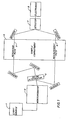
- Figure 2 shows a preferred embodiment of an instrument of the present invention that overcomes these problems and still allows stable "dual-beam" measurements to be made.
- the optical arrangement shown in Figure 2 is one possible embodiment of an apparatus that could be used to make on-line, non-contact, non-destructive dual-beam transmission measurements on a moving web.
- a light source (9) provides optical radiation over the full spectral range required by the instrument. For visible (0.4 to 0.7 ⁇ m) and near infrared (0.7 to 2.7 ⁇ m) applications, a tungsten filament lamp is preferably used as the light source (9).
- a regulated power supply (10) provides a constant source of current to ensure a stable output from the light source (9).
- a collection lens (11) is used to gather light emitted by the source (9), and direct it through an optical filter (12) located in a rotating filter wheel (13).
- the filter (12) is used to isolate the band of wavelengths at which the transmittance measurement is to be made.
- the filter (12) is usually a multilayer interference filter which can isolate a narrow band of wavelengths (e.g., less than 0.01 wm).
- the filter wheel (13) contains a number of such filters in order to effect transmittance measurements at multiple wavelengths.
- filters there are other methods of isolating narrow bands of wavelength. Among these are a moving prism or grating or tilting interference filter.
- One further alternative would be an acousto-optic tunable filter.
- the filter wheel (13) rotates at constant speed, driven by a motor (14). As each filter (12) moves into the beam of light (15) that is transmitted through the collection lens (11), it transmits its own narrow band of wavelengths. The intensity of light transmitted through each filter (12) increases as the filter moves into the beam (15), reaches a maximum when it is centered with respect to the beam , and then decreases as it moves out of the beam.
- the beam splitter (24) resides between the filter wheel (13) or dispersion device and lens (17) which directs the measurement beam to the sample (18).
- the beam splitter (24) may be a piece of glass or other such material tilted at an angle such that the reflection off the surface or surfaces is directed toward the lens (25) and forms the reference path. This type of beam splitter is preferably coated so that anywhere from 4% to 30% of the measurement beam intensity is directed into the reference path.
- the beam splitter (24) may be the polarizing element.
- An additional polarizing element can be placed in the sample beam after it has passed through the sample to act as a polarization analyzer. After the measurement beam passes through the beam splitter (24) it emerges from lens (17) and then onto the sample (18). The beam then passes through the sample (18) for the first time to a backing mirror (23). This mirror (23) reflects the beam back through the sample (18) at an angle for a second pass.
- the beam is then collected by lens (22) and directed to detector (19).
- the reference beam created by the beam splitter (24) is directed by the lens (25) to detector (19).
- a shutter mechanism (26) is disposed between lenses (22) and (25) and the detector (19). It alternately blocks either the reference beam or the measurement beam from detector (19), allowing the remaining beam to hit the detector (19).
- the detector (19) can be one of a number of photosensitive devices, including, but not limited to, silicon, germanium, lead sulfide, lead selenide, indium antimonide, mercury cadmium telluride, photomultiplier tubes or pyroelectric materials.
- the signals from the detector (19) are processed by system electronics (20) for use by a computer (21) to calculate parameters related to the material.
- This configuration can also be used for laboratory off-line measurements.
- This configuration of a measurement and a reference beam allows the technique of dual beaming to be designed into an instrument.
- the filter wheel (13) or monochromator can alternatively be located between the shutter mechanism (26) and the detector (19).
- broadband light is transmitted through both sample and reference paths, and wavelengths are isolated just before the detector (19).
- This arrangement is not preferred, for several reasons. Firstly, the use of broadband illumination can cause unwanted heating of the sample (18) or system optical elements, such as beam splitter (24) or backing mirror (23). Thermal radiation emitted by a heated sample or optical component can interfere with the desired measurement.
Landscapes
- Physics & Mathematics (AREA)
- General Physics & Mathematics (AREA)
- General Health & Medical Sciences (AREA)
- Chemical & Material Sciences (AREA)
- Analytical Chemistry (AREA)
- Biochemistry (AREA)
- Life Sciences & Earth Sciences (AREA)
- Health & Medical Sciences (AREA)
- Immunology (AREA)
- Pathology (AREA)
- Spectroscopy & Molecular Physics (AREA)
- Investigating Or Analysing Materials By Optical Means (AREA)
- Spectrometry And Color Measurement (AREA)
Applications Claiming Priority (2)
| Application Number | Priority Date | Filing Date | Title |
|---|---|---|---|
| US65420984A | 1984-09-24 | 1984-09-24 | |
| US654209 | 1984-09-24 |
Publications (2)
| Publication Number | Publication Date |
|---|---|
| EP0176826A2 true EP0176826A2 (fr) | 1986-04-09 |
| EP0176826A3 EP0176826A3 (fr) | 1987-09-02 |
Family
ID=24623905
Family Applications (1)
| Application Number | Title | Priority Date | Filing Date |
|---|---|---|---|
| EP85111475A Withdrawn EP0176826A3 (fr) | 1984-09-24 | 1985-09-11 | Méthode et appareil pour la mesure de transmission spectrale à double faisceau |
Country Status (2)
| Country | Link |
|---|---|
| EP (1) | EP0176826A3 (fr) |
| JP (1) | JPS6189543A (fr) |
Cited By (6)
| Publication number | Priority date | Publication date | Assignee | Title |
|---|---|---|---|---|
| EP0251225A3 (fr) * | 1986-06-27 | 1990-02-14 | J. Hirschmann Gerätebau GmbH & Co.KG | Appareil pour former l'image d'un objet sur un transducteur électro-optique |
| WO1996024833A1 (fr) * | 1995-02-08 | 1996-08-15 | Daniel Jonathan Seeman | Procede et systeme de controle d'un materiau a tester |
| EP0802430A3 (fr) * | 1996-04-18 | 1999-06-23 | Sick AG | Capteur opto-électronique |
| US6452717B1 (en) | 1999-02-05 | 2002-09-17 | Sumitomo Electric Industries, Ltd. | Fiber optic amplifier |
| WO2020033163A1 (fr) * | 2018-08-06 | 2020-02-13 | Thermo Electron Scientific Instruments Llc | Monochromateur avec réduction de la lumière parasite |
| CN114383539A (zh) * | 2021-12-16 | 2022-04-22 | 天津大学 | 一种激光分束与折叠光路系统 |
Families Citing this family (5)
| Publication number | Priority date | Publication date | Assignee | Title |
|---|---|---|---|---|
| JPH02156136A (ja) * | 1988-12-07 | 1990-06-15 | Power Reactor & Nuclear Fuel Dev Corp | 分光分析装置 |
| DE3940386A1 (de) * | 1989-12-06 | 1991-06-13 | Minnesota Mining & Mfg | Vorrichtung zum messen der transmission filmartiger folien und dergleichen |
| AT408488B (de) * | 1999-12-22 | 2001-12-27 | Scan Messtechnik Gmbh | Miniaturisiertes spektrometer |
| JP4774186B2 (ja) * | 2000-08-18 | 2011-09-14 | 東京エレクトロン株式会社 | 偏光を削減する小スポット分光測定器具 |
| JP6414257B2 (ja) * | 2017-03-16 | 2018-10-31 | 株式会社Ihi | 濃度測定装置及び濃度測定方法 |
Family Cites Families (7)
| Publication number | Priority date | Publication date | Assignee | Title |
|---|---|---|---|---|
| JPS5933204B2 (ja) * | 1976-01-30 | 1984-08-14 | 株式会社日立製作所 | 二光束分光光度計 |
| JPS5466190A (en) * | 1977-11-04 | 1979-05-28 | Hitachi Ltd | Two luminous flux spectrophotometer |
| JPS55116217A (en) * | 1979-03-02 | 1980-09-06 | Hitachi Ltd | Display unit |
| GB2045923B (en) * | 1979-03-05 | 1983-01-26 | Pye Electronic Prod Ltd | Spectrophotometer |
| JPS582641U (ja) * | 1981-06-29 | 1983-01-08 | 株式会社島津製作所 | 分光光度計 |
| JPS5899733A (ja) * | 1981-12-08 | 1983-06-14 | Mitsubishi Electric Corp | 濁度計 |
| DD207984A1 (de) * | 1982-03-01 | 1984-03-21 | Hartmut Heinz | Verfahren zur bestimmung der wellenlaenge, wellenzahl oder frequenz |
-
1985
- 1985-09-11 EP EP85111475A patent/EP0176826A3/fr not_active Withdrawn
- 1985-09-24 JP JP21203485A patent/JPS6189543A/ja active Pending
Cited By (8)
| Publication number | Priority date | Publication date | Assignee | Title |
|---|---|---|---|---|
| EP0251225A3 (fr) * | 1986-06-27 | 1990-02-14 | J. Hirschmann Gerätebau GmbH & Co.KG | Appareil pour former l'image d'un objet sur un transducteur électro-optique |
| WO1996024833A1 (fr) * | 1995-02-08 | 1996-08-15 | Daniel Jonathan Seeman | Procede et systeme de controle d'un materiau a tester |
| EP0802430A3 (fr) * | 1996-04-18 | 1999-06-23 | Sick AG | Capteur opto-électronique |
| US6091071A (en) * | 1996-04-18 | 2000-07-18 | Sick Ag | Opto-electronic sensor |
| US6452717B1 (en) | 1999-02-05 | 2002-09-17 | Sumitomo Electric Industries, Ltd. | Fiber optic amplifier |
| WO2020033163A1 (fr) * | 2018-08-06 | 2020-02-13 | Thermo Electron Scientific Instruments Llc | Monochromateur avec réduction de la lumière parasite |
| US11067445B2 (en) | 2018-08-06 | 2021-07-20 | Thermo Electron Scientific Instruments Llc | Monochromator with stray light reduction |
| CN114383539A (zh) * | 2021-12-16 | 2022-04-22 | 天津大学 | 一种激光分束与折叠光路系统 |
Also Published As
| Publication number | Publication date |
|---|---|
| EP0176826A3 (fr) | 1987-09-02 |
| JPS6189543A (ja) | 1986-05-07 |
Similar Documents
| Publication | Publication Date | Title |
|---|---|---|
| EP2188604B1 (fr) | Spectromètre pour mesurer la matière d'un échantillon en mouvement et procédé correspondant | |
| US4081215A (en) | Stable two-channel, single-filter spectrometer | |
| US4822169A (en) | Measuring assembly for analyzing electromagnetic radiation | |
| US6870619B1 (en) | Spectrometer and method for measuring optical spectrum | |
| US3853407A (en) | Multiple path spectrophotometer method and apparatus | |
| US5751418A (en) | Spectrometry and optical method and apparatus for obtaining a stable spectrum with use of an informationless spectrum contained therein | |
| US5952660A (en) | Method of identifying post consumer or post industrial waste carpet utilizing a hand-held infrared spectrometer | |
| US5920069A (en) | Apparatus for automatic identification of gas samples | |
| JPH0580615B2 (fr) | ||
| JPS589362B2 (ja) | 赤外線多層フイルム膜厚測定方法及びその測定装置 | |
| WO1997028428A1 (fr) | Etalon programmable destine a un appareil et procede de mesure non invasive de composes optiquement absorbants | |
| CA2061352A1 (fr) | Systeme d'etalonnage automatique pour spectrophotometre | |
| CA2479334A1 (fr) | Analyseur haute vitesse utilisant le rayonnement infrarouge proche transmis a travers les echantillons epais d'un materiau optiquement dense | |
| GB2128359A (en) | Double-beam spectrophotometer | |
| US5305077A (en) | High-resolution spectroscopy system | |
| US4577105A (en) | Method of determining masses of absorbing components of a sample in a test volume and a device for implementation of this method | |
| JPS6189543A (ja) | デユアルビームスペクトル透過率の測定方法及び装置 | |
| JPH0580981B2 (fr) | ||
| WO2006058741A1 (fr) | Spectrophotometre | |
| EP3913339B1 (fr) | Spectrophotometre | |
| US4838691A (en) | Method and apparatus for determining calibration accuracy of a scientific instrument | |
| Landa | High‐energy spectrophotometer for rapid constituent analysis in the range of 0.25–2.4 μm | |
| EP0091535A2 (fr) | Spectrophotomètre avec étalonnage en longueur d'ondes | |
| JP4486805B2 (ja) | 分光分析装置 | |
| CA1184652A (fr) | Analyseur optique a monochromateur a reseau pour l'infrarouge proche |
Legal Events
| Date | Code | Title | Description |
|---|---|---|---|
| PUAI | Public reference made under article 153(3) epc to a published international application that has entered the european phase |
Free format text: ORIGINAL CODE: 0009012 |
|
| AK | Designated contracting states |
Kind code of ref document: A2 Designated state(s): CH DE FR GB LI |
|
| 17P | Request for examination filed |
Effective date: 19860911 |
|
| PUAL | Search report despatched |
Free format text: ORIGINAL CODE: 0009013 |
|
| RHK1 | Main classification (correction) |
Ipc: G01J 3/42 |
|
| AK | Designated contracting states |
Kind code of ref document: A3 Designated state(s): CH DE FR GB LI |
|
| STAA | Information on the status of an ep patent application or granted ep patent |
Free format text: STATUS: THE APPLICATION IS DEEMED TO BE WITHDRAWN |
|
| 18D | Application deemed to be withdrawn |
Effective date: 19880303 |
|
| RIN1 | Information on inventor provided before grant (corrected) |
Inventor name: KISHNER, STANLEY J. Inventor name: KRAVETZ, ALAN G. |