EP0176894A2 - Fabrication d'une lentille torique - Google Patents
Fabrication d'une lentille torique Download PDFInfo
- Publication number
- EP0176894A2 EP0176894A2 EP85111957A EP85111957A EP0176894A2 EP 0176894 A2 EP0176894 A2 EP 0176894A2 EP 85111957 A EP85111957 A EP 85111957A EP 85111957 A EP85111957 A EP 85111957A EP 0176894 A2 EP0176894 A2 EP 0176894A2
- Authority
- EP
- European Patent Office
- Prior art keywords
- lens
- curve
- cross
- axis
- angle
- Prior art date
- Legal status (The legal status is an assumption and is not a legal conclusion. Google has not performed a legal analysis and makes no representation as to the accuracy of the status listed.)
- Granted
Links
Images


Classifications
-
- B—PERFORMING OPERATIONS; TRANSPORTING
- B24—GRINDING; POLISHING
- B24B—MACHINES, DEVICES, OR PROCESSES FOR GRINDING OR POLISHING; DRESSING OR CONDITIONING OF ABRADING SURFACES; FEEDING OF GRINDING, POLISHING, OR LAPPING AGENTS
- B24B13/00—Machines or devices designed for grinding or polishing optical surfaces on lenses or surfaces of similar shape on other work; Accessories therefor
- B24B13/04—Machines or devices designed for grinding or polishing optical surfaces on lenses or surfaces of similar shape on other work; Accessories therefor grinding of lenses involving grinding wheels controlled by gearing
- B24B13/043—Machines or devices designed for grinding or polishing optical surfaces on lenses or surfaces of similar shape on other work; Accessories therefor grinding of lenses involving grinding wheels controlled by gearing using cup-type grinding wheels
Definitions
- the present invention relates to methods and apparatus for generating toric surfaces, and particularly for grinding of ophthalmic lenses having toric surfaces.
- the invention has as its principal object to provide improved methods and apparatus for the control of toric lens cutting machines which utilize cup-shaped cutter wheels. Such wheels are rotated or swept about an axis perpendicular to the lens axis.
- the curve generated in the plane perpendicular to the sweep axis known herein as the base curve, and whether the lens is concave or convex, are determined by the location of the sweep axis with respect to the lens (forward of the lens for a concave lens and to the rear of the lens for a convex lens).
- the base curve as is desired for a true toric surface, is an arc of a circle whose curvature is determined by the distance between the sweep axis and the center of the lens surface.
- the curve in the direction orthogonal to the base curve, or equivalently in the direction parallel to the sweep axis, is known herein as the cross curve.
- the angle of orientation of the cutter wheel determines the power of the cross curve.
- Such cross curves for reasons inherent in the geometry of the grinding machine, are generated with errors commonly known as "elliptical errors".
- the cross curve which is cut deviates from the true circular arc which is ideally desired.
- the cross curve is closer in shape to an elliptical arc than to a circular one, but its actual shape is in fact more complicated than an elliptical arc.
- the invention provides methods and apparatus whereby toric lenses can be cut on such grinding machines with cup-shaped cutter wheels at high speed and at low cost.
- the invention is especially suitable for ophthalmic lens grinding purposes, it may also be applied wherever the generation of toric surfaces is called for.
- base and cross curve used herein differ from the terminology commonly used in the ophthalmic industry where the cross and base curves are, respectively, the curves with smaller and larger radius. The terminology is, however, minos identical for/surfaces cut in accordance with this invention.
- Toric lens grinding machines which utilize cup-shaped cutter wheels have been in use for some time. Such machines and their operation are described in US Patent Nos. 2,548,418 issued April 10, 1951, 2,633,675 issued April 7, 1953, 2,724,218 issued November 22, 1955, 2,806,327 issued September 17, 1957, 3,289,355 issued December 12, 1966, 3,492,764 issued February 2, 1970, 3,624,969 issued December 7, 1971, and 3,790,875 issued February 5, 1974. Digital controls for such machines are described in the above-mentioned US Patent 3,790,875. This patent also mentions the known technique of adjusting for elliptical error by the use of a "correction factor", i.e.
- a correction is made in the angular orientation of the cutter wheel to obtain a cross curve lens power (D c ) which is incremented as a function of the difference between the cross curve and base curve powers by an amount equal to f(D B -D C ) where f is a positive number.
- D c cross curve lens power
- f a positive number.
- the selection of a suitable value of f is determined by trial and error and depends upon the experience of the manufacturing optician. Sometimes, especially when there is a large difference between D and DB' the elliptical error is large enough to cause lens fracture in the subsequent smoothing stage. Sometimes several sweeps of the cutter wheel unit are used, with the lens progressively moved along its optic axis towards the cutter, in order not to remove excessive material during each cut. However only the final cut affects the shape of the curve which is generated, and this shape contains elliptical errors which can only be partially compensated for by the above-mentioned correction factor.
- a third approach described in US Patent 3,117,396 issued January 14, 1964 proposes the elimination of the problem by the use of a large number of cutter wheels which do not have a conventional cup-shaped cutting surface, but instead are shaped so that they supposedly cut an exact (circular) cross curve without elliptical error and without adversely affecting the base curve.
- a large collection of cutter wheels is needed, which must be frequently dressed and maintained in order to accomplish the purpose of doing away with elliptical error.
- the invention provides for the generation of toric surfaces and particularly of a lens having a toric surface with base and cross curvatures of different radii.
- a cutter unit having a cutter wheel which rotates about an axis perpendicular to the axis of the lens, and preferably a cup-shaped cutter wheel, is used. These rotations are referred to as sweeps.
- a plurality of such sweeps is used to make a plurality of cuts.
- the location of the cutter wheel with respect to the lens and the orientation of the cutter wheel are changed prior to each cut in the cuts made during sweeps subsequent to the initial cut, the elliptical error in different portions of the cross curve being thereby reduced.
- This provides a toric surface in which the elliptical error is minimized with a few cuts and without cutting into the surface of the lens which would introduce errors or require additional smoothing to achieve the requisite toric surface.
- FIG. 12 there is shown a cup-shaped cutter wheel 20 having a nose 10.
- the cutter wheel is mounted on a spindle 22 which is rotated about the axis of the wheel, indicated as the x axis in FIG. 12, by a motor 24.
- the cutter wheel 20, its spindle 22 and motor 24 constitute the cutter unit or cutter assembly.
- This unit is mounted, as explained in greater detail in the above-referenced patent, on a headslide 27 which can slide along a headstock 26 so that the center F of the nose remains on the headstock center line HCL.
- the headstock is pivotally mounted on the machine base 28 for rotation about a vertical axis PP'.
- This axis PP' is along the center line of a tailstock 30 on which the lens to be cut (shown in the form of a lens blank 32) is mounted.
- the center line of the tailstock is the optical axis x' of the lens.
- the tailstock 30 is mounted in a tailstock slide 34. It will be appreciated that the apparatus so far described is viewed from the top and the various center lines lie in a plane perpendicular to the rotation or sweep axis PP' and through the meridian of the lens 32.
- the tailstock 30 is shown as being stationary while the cutting unit rotates about the axis PP', it will be appreciated that the tool may be stationary and the lens rotated about the axis P P '; however the use of a rotating tool is conventional and is preferred. Further information respecting the design of the toric lens grinding machine, so far as its cutting tool assembly, headstock, tailstock and mechanisms for adjusting and rotating same are concerned, will be found in the above-referenced Patent 3,790,875.
- the positions of the sweep axis PP' and the cutting unit are shown for the cutting of convex or plus lenses. The positions of these units and the axis PP' for the cutting of concave or negative lenses will be apparent from the above-referenced Patent 3,790,875.
- Motors 40, 42, 44 and 46 are used to actuate the components of the cutting machine.
- the motors are typically stepper motors.
- Motor 44 is connected through a rotation drive such as a gear box to the shaft which rotates the headstock 26 about the sweep axis PP'.
- the motor 40 has an output through a linear drive (e.g., a lead screw) to translate the cutter unit along the headstock center line HCL.
- the motor 42 has an output through a rotation drive, such as a gear box, to tilt or incline the cutter unit x axis with respect to the headstock center line. This center line passes through the sweep axis PP' and the center F of the nose 10.
- the nose is semicircular in cross section and is a half torus of major radius from 0 to F; 0 being the intersection of the base line 21 through the center F of the nose 10 and the axis of rotation x of the cutter wheel 20.
- the tailstock 30 is driven by the stepper motor 46 through a linear drive, such as a lead screw.
- Digital to step converters (DSC) 48, 50, 52 and 54 translate control signals from digital circuitry which sets the angle of inclination 8 and moves the tailstock 30 so as to displace the lens by distances ⁇ prior to successive sweeps.
- An output is obtained from the rotation drive to the headstock 26, which sweeps the headstock about the vertical axis PP', to a sweep counter 56.
- An input device 58 such as a keyboard, inputs the values of the base curve power D B , the cross curve power D C , the refractive index of the lens n, the sign of the lens, and a wear factor W f to a command store 60. However, before being stored in the command store 60, the input values of D B and D C are adjusted by refractive index correction logic 70 to correspond to a reference refractive index n 0 (e.g. 1.523). This enables the machine to operate with lens materials having various refractive indices.
- the command store has memory for the digital signals for each of the commands and applies them to address a memory 64 which stores digital signals corresponding to different orientation angles 6 and different displacements A for a range of values of base curve power D B and cross curve power D C .
- adjustment values ⁇ corresponding to the nose wear factor as discussed hereinafter, especially with reference to FIG. 5A.
- the values of ⁇ and ⁇ which are used are selected, depending upon which of the three sweeps is to be carried out, by means of the sweep counter 56. In the event that
- interpolation logic 68 is used.
- the interpolation logic carries out conventional bilinear interpolation to obtain values of 8 and ⁇ which are weighted in accordance with the proximity of the selected intermediate values ( DC , D B ) from the closest points (D C , D B ) thereto at which the values of ⁇ and ⁇ are stored in the memory 64.
- the outputs from the store 64 are passed through nose wear correction logic 72.
- the output of the logic 72 which like the logic components 68 and 70 interposes no correction or interpolation if none is required, produces digital signals corresponding to the D B and D C curve powers.
- the D B curve power is determined by a signal representing the base radius R B (see Eqn. (4) below) and the D C curve power is determined by a signal representing the angle 8.
- the R B and ⁇ signals will adjust the location of the cutter tool along the x axis and the location of the tailstock 30 with respect to the pivot or sweep axis PP', by application of appropriate digital signals to the DSCs 48 and 54.
- the command store 60 initiates the sweeps of the headstock 26 through the DSC 52, the stepper motor 44 and its rotation drive. On subsequent sweeps different values are inputted to the DSCs 50 and 54 to adjust the angle 8 and the location of the lens relative to the cutter unit. Accordingly, with only a few sweeps, the lens 32 can be cut with a minimum of elliptical error.
- the system described may also be used for a cutter unit which is mounted on an xy table and which is permitted to rotate thereon about a vertical axis through an angle ⁇ .
- the cutter unit may be made to execute sweeps or rotations about the axis PP' geometrically equivalent to the rotations described above.
- the inclinations 8 are then set by the ⁇ stepper motor prior to each sweep and the displacements A may be set by the x or y stepper motor prior to each sweep rather than by motion of the tailstock.
- Translation logic will be needed for each of the x and y stepper motors which drive the table. Such logic is conventionally utilized with xy tables, as are used in plotters and computer aided machine tools. Similar logic is used for the ⁇ stepper motor.
- FIG. 12 may of course be implemented in a computer program of a digital computer to carry out the functions herein described.
- This computer will have a memory 80 (see FIG. 13) containing the parameters 8 and A for successive sweeps at different combinations of D C less than D B for a plus lens and D c greater than D B for a minus lens. Only these two cases are needed since the base and cross curves are at 90 decrees to each other, and the lens may simply be rotated 90 degrees to provide the conjugate relationships of D B to D C .
- the table values in the memory are generated by a computer 82, preferably off-line, which calculates families of lens surface curves at successive cutter inclinations 8 and outputs successive 8 and A settings appropriate for generating accurate toric surfaces at each of 11 D C values at each base curve power value D B , 11 of which may also be provided.
- a computer 82 preferably off-line, which calculates families of lens surface curves at successive cutter inclinations 8 and outputs successive 8 and A settings appropriate for generating accurate toric surfaces at each of 11 D C values at each base curve power value D B , 11 of which may also be provided.
- the cutter unit 84 represents the headstock 26, headslide 27 and the cutter wheel unit mounted thereon, together with its drives and stepper motors.
- the lens unit 86 represents the tailstock 30 and its drive and stepper motor.
- the computer controller 88 fetches the values from memory as dictated by the input device 90 and performs the interpolation, refractive index correction and cutter wear correction routines, if required.
- the computer outputs the ⁇ , ⁇ and R B control signals as well as the sweep control signals which command the sweeps.
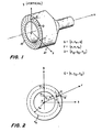
- FIGS. 1 through 11 In order to calculate the actual cross curve cut by a single sweep of the cup tool, and define parameters specifying an appropriate series of sweeps, reference is made now to FIGS. 1 through 11. We shall first describe in detail how a plus curve is calculated; it will become apparent that a minus curve is calculated in a very similar fashion.
- FIG. 1 is a perspective diagram of the cup tool showing a coordinate system Oxyz embedded in the tool.
- FIG. 1 is schematic and is not drawn to scale.
- Ox is the axis of spin of the cutter wheel and lies in the horizontal plane.
- Oy is the vertical axis and passes through the point G.
- Oz is the other axis in the horizontal plane and passes through the point F.
- the points F and G both lie on a circle of radius r W , which will be termed the wheel radius, and center O.
- An exemplary point D on the cutting surface will have coordinates (x D , y D , z D ) relative to the coordinate system Oxyz.
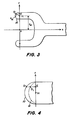
- FIG. 3 shows a cross section of the cutter wheel in the plane containing the horizontal axis Ox and the radial line Or passing through E.
- the point H lies on the above-mentioned circle of radius r w which passes through F and G.
- the cross section of the nose 10 is circular with radius r N .
- this method is not restricted to the nose cross section being circular, as it is possible to determine x D from y D and z D in other cases as well.
- the point D on the cutting surface would be located, instead, at D 1 .
- the distance x D would then be equal to (-D 1 E).
- the curve 12 is measured, digitized and stored as a look-up table in a computer memory, thereby giving the distance D 1 E as a function of radius r D .
- the curve can also be approximated as an analytic function such as an ellipse.
- FIG. 5 shows a cross section of the tool in this horizontal plane, with the vertical axis positioned relative to the tool in a configuration suitable for generating a plus surface.
- P is positioned in what we shall term the "nominal" position for generating a surface of base and cross radii, R B and R C respectively; the line PF is set at an angle 8 to the cutter axis Ox where and P is taken to be a distance R B from the nearest point on the cutter, I.
- the points F, I and P lie on a straight line and P is positioned at a distance R B +r N from the reference point F.
- the shape of the cross curve (in the vertical plane) will be seen to depend on the angle 9.
- a series of sweeps of the cutter about the vertical axis through P (PP' in FIG. 12) with different but appropriately selected values of 8
- a very close approximation to the true cross curve (a circle of radius R C ) will be generated. It is found that, in order for benefit to be made from the use of such a series of sweeps, a plus lens should be cut with RC > R B , as indicated in FIG. 5, and a minus lens should be cut with R B > R C , as indicated in FIG. 11.
- the intersection of the vertical rotation axis (PP' in FIG. 12) with this plane is the point P', which has coordinates (x P , y D , z P ).
- the curve 20 generated in this plane is a circle of radius P'D' where D' is the point on curve 18 closest to P'.
- points on curve 18 such as D, lying between M and N, are scanned. It is convenient to scan a series of values z D , lying between the distances KN and KM; the unknown coordinate x is found from Eqns. (1) and (2), or from Eqn. (1) and a digitized nose cross section, as discussed above.
- the distance P'D is given from Pythagoras' Theorem by By scanning sufficient values z D' the distance P'D' can be found to any desired degree of accuracy.
- FIG. 7 The form of the cross curve generated in the vertical plane containing the axis of rotation (PP') of the cutter wheel and the center of the lens surface R is shown in FIG. 7.
- Distance P'D' in FIG. 6 is distance R y in FIG. 7.
- Curve (a) is the desired circle of radius R C .
- Vertical and horizontal axes in this plane are indicated as Ry' and Rx' respectively.
- the point S on curve (a) at height y is given by since, by Pythagoras' Theorem applied to triangle UWS, It is desired that as much glass as possible be removed from the left of curve (a), but without removing any glass from the right of curve (a).
- the distance ⁇ may be calculated to any desired degree of accuracy by calculating the error at a sufficiently large number of heights y' and setting A to be the largest such error.
- Cutting curve (c) would have the undesirable effect of cutting to the right of the lens surface (curve (a)), to a maximum error depth of ⁇ , which error would have to be corrected for at a subsequent smoothing stage in the manufacture of the lens. It is easy to see that if a relative displacement between the lens and the cutting assembly is made prior to the sweep at angle ⁇ ', as can easily be effected by withdrawing the lens a distance ⁇ along the tailstock slide, the effective cutting curve will be the curve (c'), obtained by translating the curve (c) a distance A to the left in FIG. 8. The curve (c') will touch the correct curve (a) at the height y l , and provide a close approximation to the correct curve (a) in the vicinity of y l .
- each curve indicates the error, i.e. the deviation from the true cross curve or equivalently the thickness of glass remaining to be cut, as a function of the distance y' above (or below) the center of the lens.
- Curve 1 generated by the first sweep, corresponds to the curve (b) of FIG. 7, and is determined by the ⁇ given by E qn. (3).
- Curve 3 is next obtained by calculating a number of curves with modified angles ⁇ ' corresponding to values of D C ' between D C and D B , and selecting from these a curve which gives an acceptably small error (0.06 mm here) at the edge of the lens (35 mm here).
- the remaining curve, curve 2 may be obtained by calculating intermediate curves with diopter values D C ' between D C1 and D C3 until the errors y L ' and y R ' at the intersections with curves 1 and 3 respectively are equal.
- FIG. 14 is a schematic drawing of a convex surface generated by these three cuts 1-3, illustrating how the desired true curve 39 is approximated and showing the glass remaining after the three cuts as the shaded area.
- Curve 3 could be selected to have zero error on the edge.
- FIG. 10 An example of the use of 5 sweeps is shown in FIG. 10 for the same lens.
- the vertical scale here has been expanded by a factor of 10 in comparison with FIG. 9. Again the shaded area indicates the resultant error, i.e. glass remaining and needing to be removed.
- Adjustments to the relative positions of the lens and the cutter assembly are made as for plus curves to ensure that no glass is cut beyond the exact surface of the lens; in both cases the displacements are in the direction that moves the lens away from the cutter.
- the tables are stored in a Programmable Read-Only Memory (PROM) in a microprocessor controlling the lens-generating machine, and standard interpolation techniques (e.g. bilinear interpolation) are then used to interpolate the appropriate parameters for the lens surface being ground, as explained above in connection with FIGS. 12 and 13.
- PROM Programmable Read-Only Memory
- standard interpolation techniques e.g. bilinear interpolation
- microprocessor controlling the lens-generating machine periodically during the life of the cutter.
- One practical way to compensate for cutter wear is to store two sets of tables in the PROM, one for a true nose cross section and one for a representative well-worn cross section.
- the microprocessor may calculate the parameters ⁇ i , ⁇ i and ⁇ i from each set of tables, and take a weighted average of each of these parameters dependent on the estimated degree of wear which may be periodically set into the microprocessor by the operator.
- the refractive index needs to be known (see Eqn. (4)). Rather than store one set of tables for each refractive index, it is preferable to store a single set of tables for a reference refractive index n 0 (e.g. 1.523); then, when specified diopter values are desired for a lens material of a different refractive index, n l say, these specified diopter values are first subject to an elementary adjustment, namely multiplication by the factor (n 0 -1)/(n 1 -1), before making use of the tables.
- n 0 e.g. 1.523
Landscapes
- Engineering & Computer Science (AREA)
- Mechanical Engineering (AREA)
- Grinding And Polishing Of Tertiary Curved Surfaces And Surfaces With Complex Shapes (AREA)
- Materials For Medical Uses (AREA)
- Eyeglasses (AREA)
Priority Applications (1)
| Application Number | Priority Date | Filing Date | Title |
|---|---|---|---|
| AT85111957T ATE58857T1 (de) | 1984-10-05 | 1985-09-20 | Torische linsenerzeugung. |
Applications Claiming Priority (2)
| Application Number | Priority Date | Filing Date | Title |
|---|---|---|---|
| US06/658,343 US4574527A (en) | 1984-10-05 | 1984-10-05 | Toric lens generating |
| US658343 | 1996-06-05 |
Publications (3)
| Publication Number | Publication Date |
|---|---|
| EP0176894A2 true EP0176894A2 (fr) | 1986-04-09 |
| EP0176894A3 EP0176894A3 (en) | 1988-07-20 |
| EP0176894B1 EP0176894B1 (fr) | 1990-12-05 |
Family
ID=24640858
Family Applications (1)
| Application Number | Title | Priority Date | Filing Date |
|---|---|---|---|
| EP85111957A Expired - Lifetime EP0176894B1 (fr) | 1984-10-05 | 1985-09-20 | Fabrication d'une lentille torique |
Country Status (5)
| Country | Link |
|---|---|
| US (1) | US4574527A (fr) |
| EP (1) | EP0176894B1 (fr) |
| JP (1) | JPS6190864A (fr) |
| AT (1) | ATE58857T1 (fr) |
| DE (1) | DE3580821D1 (fr) |
Cited By (3)
| Publication number | Priority date | Publication date | Assignee | Title |
|---|---|---|---|---|
| EP0453094A3 (en) * | 1990-04-18 | 1992-04-01 | Pilkington Visioncare Inc. | Lens grinding method and apparatus |
| US5181345A (en) * | 1990-04-18 | 1993-01-26 | Coburn Optical Industries, Inc. | Lens grinding method and apparatus |
| FR2687598A1 (fr) * | 1992-02-26 | 1993-08-27 | Cmvm International | Machine et procede pour generer par meulage une surface quelconque de lentille optique ou ophtalmique. |
Families Citing this family (14)
| Publication number | Priority date | Publication date | Assignee | Title |
|---|---|---|---|---|
| US4989316A (en) * | 1987-03-09 | 1991-02-05 | Gerber Scientific Products, Inc. | Method and apparatus for making prescription eyeglass lenses |
| EP0305471B1 (fr) * | 1987-03-13 | 1993-12-29 | The Gleason Works | Outil rotatif de dressage, procede et appareil de dressage de meules convexes |
| US5085007A (en) * | 1989-09-11 | 1992-02-04 | Coburn Optical Industries | Toric lens fining apparatus |
| US5217335A (en) * | 1990-04-24 | 1993-06-08 | National Optronics, Inc. | Plastic lens generator and method |
| US5231587A (en) * | 1990-07-12 | 1993-07-27 | Loh Optical Machinery, Inc. | Computer controlled lens surfacer |
| US5052153A (en) * | 1990-09-06 | 1991-10-01 | Wiand Ronald C | Cutting tool with polycrystalline diamond segment and abrasive grit |
| US5210695A (en) * | 1990-10-26 | 1993-05-11 | Gerber Optical, Inc. | Single block mounting system for surfacing and edging of a lens blank and method therefor |
| DE19529786C1 (de) * | 1995-08-12 | 1997-03-06 | Loh Optikmaschinen Ag | Verfahren und Werkzeug zur Erzeugung einer konkaven Oberfläche an einem Brillenglasrohling |
| US5957637A (en) * | 1997-11-13 | 1999-09-28 | Micro Optics Design Corp. | Apparatus and method for generating ultimate surfaces on ophthalmic lenses |
| FR2823143B1 (fr) * | 2001-04-10 | 2003-07-04 | Essilor Int | Outil torique de polissage d'une surface optique d'une lentille, et procede de polissage d'une surface atorique au moyen d'un tel outil |
| US20060011617A1 (en) * | 2004-07-13 | 2006-01-19 | Ricardo Covarrubias | Automated laser cutting of optical lenses |
| US8665160B2 (en) | 2011-01-31 | 2014-03-04 | Apple Inc. | Antenna, shielding and grounding |
| US8587939B2 (en) | 2011-01-31 | 2013-11-19 | Apple Inc. | Handheld portable device |
| US8911280B2 (en) * | 2011-01-31 | 2014-12-16 | Apple Inc. | Apparatus for shaping exterior surface of a metal alloy casing |
Family Cites Families (19)
| Publication number | Priority date | Publication date | Assignee | Title |
|---|---|---|---|---|
| US2548418A (en) * | 1947-12-19 | 1951-04-10 | American Optical Corp | Surfacing machine |
| US2589488A (en) * | 1948-11-19 | 1952-03-18 | Shuron Optical Co Inc | Lens grinding method and machine |
| US2633675A (en) * | 1950-06-10 | 1953-04-07 | American Optical Corp | Surfacing machine |
| US2724218A (en) * | 1953-08-19 | 1955-11-22 | American Optical Corp | Surfacing machines |
| US2806327A (en) * | 1954-03-03 | 1957-09-17 | Orin W Coburn | Lens grinder |
| US3117396A (en) * | 1961-01-17 | 1964-01-14 | American Optical Corp | Lens grinding apparatus and method |
| US3289355A (en) * | 1963-04-22 | 1966-12-06 | Coburn Mfg Company Inc | Automatic lens grinding machine |
| US3399496A (en) * | 1965-05-12 | 1968-09-03 | Textron Inc | Machine for generating toric surfaces |
| US3492764A (en) * | 1967-03-28 | 1970-02-03 | American Optical Corp | Lens generating method |
| GB1290685A (fr) * | 1969-10-16 | 1972-09-27 | ||
| US3624969A (en) * | 1970-07-15 | 1971-12-07 | American Optical Corp | Lens generating apparatus |
| US3790875A (en) * | 1970-11-27 | 1974-02-05 | Autoflow Eng Ltd | Digital to analogue converter |
| US3824742A (en) * | 1972-07-07 | 1974-07-23 | Itek Corp | Toric surface generating method and apparatus |
| US4068413A (en) * | 1975-10-02 | 1978-01-17 | Suddarth Jack M | Adjustable lens grinding apparatus |
| DE2659489A1 (de) * | 1976-12-30 | 1978-07-13 | Prontor Werk Gauthier Gmbh | Maschine zum fraesen asphaerischer, insbesondere torischer flaechen von optischen glaesern, beispielsweise brillenglaeser |
| DK338978A (da) * | 1977-08-02 | 1979-02-03 | Automated Optics | Kontaktlinse samt fremgangsmaade og maskine til fremstilling af saadanne linser |
| US4271636A (en) * | 1979-09-21 | 1981-06-09 | American Optical Corporation | Lens generating apparatus |
| US4264249A (en) * | 1979-08-24 | 1981-04-28 | American Optical Corporation | Toric surface generator |
| FR2528748A1 (fr) * | 1982-06-18 | 1983-12-23 | Essilor Int | Machine pour usiner des surfaces courbes |
-
1984
- 1984-10-05 US US06/658,343 patent/US4574527A/en not_active Expired - Lifetime
-
1985
- 1985-09-20 DE DE8585111957T patent/DE3580821D1/de not_active Expired - Lifetime
- 1985-09-20 AT AT85111957T patent/ATE58857T1/de not_active IP Right Cessation
- 1985-09-20 EP EP85111957A patent/EP0176894B1/fr not_active Expired - Lifetime
- 1985-10-03 JP JP60219281A patent/JPS6190864A/ja active Pending
Cited By (4)
| Publication number | Priority date | Publication date | Assignee | Title |
|---|---|---|---|---|
| EP0453094A3 (en) * | 1990-04-18 | 1992-04-01 | Pilkington Visioncare Inc. | Lens grinding method and apparatus |
| US5181345A (en) * | 1990-04-18 | 1993-01-26 | Coburn Optical Industries, Inc. | Lens grinding method and apparatus |
| FR2687598A1 (fr) * | 1992-02-26 | 1993-08-27 | Cmvm International | Machine et procede pour generer par meulage une surface quelconque de lentille optique ou ophtalmique. |
| WO1993016842A1 (fr) * | 1992-02-26 | 1993-09-02 | C.M.V.B. International | Machine et procede pour generer par meulage une surface quelconque de lentille optique ou ophtalmique |
Also Published As
| Publication number | Publication date |
|---|---|
| US4574527A (en) | 1986-03-11 |
| ATE58857T1 (de) | 1990-12-15 |
| JPS6190864A (ja) | 1986-05-09 |
| EP0176894B1 (fr) | 1990-12-05 |
| DE3580821D1 (de) | 1991-01-17 |
| EP0176894A3 (en) | 1988-07-20 |
Similar Documents
| Publication | Publication Date | Title |
|---|---|---|
| EP0176894B1 (fr) | Fabrication d'une lentille torique | |
| US4989316A (en) | Method and apparatus for making prescription eyeglass lenses | |
| US3913274A (en) | Method and apparatus for making integrated multifocal lenses | |
| CN100372648C (zh) | 抛光的设备和方法 | |
| US4768308A (en) | Universal lens polishing tool, polishing apparatus and method of polishing | |
| US5139005A (en) | Universal dressing roller and method and apparatus for dressing cup-shaped grinding wheels | |
| US4947715A (en) | Method and apparatus for cutting an aspheric surface on a workpiece | |
| EP0518640B1 (fr) | Procédé et dispositif pour chanfreiner l'encoche d'une plaquette | |
| EP0370788B1 (fr) | Procédé et dispositif pour tailler une surface asphérique sur une pièce | |
| JPH07256547A (ja) | レンズ縁取システム | |
| JPH0487701A (ja) | 非球面レンズの製造装置 | |
| KR100659433B1 (ko) | 비구면 가공 방법, 비구면 형성 방법 및 비구면 가공 장치 | |
| US5107628A (en) | Method of fabricating article having aspheric figure and tool for use in carrying out the method | |
| US4264249A (en) | Toric surface generator | |
| JPH0516980B2 (fr) | ||
| US6712675B1 (en) | Method for grinding at least one surface on a cutting knife used in machining, use of said method and grinding wheel used to carry out said method | |
| JPH05509043A (ja) | 長手方向に湾曲した歯のギヤの歯を形成する方法 | |
| US4686796A (en) | Method and apparatus for improved polishing of turbine blades | |
| US3902277A (en) | Method and apparatus for generating toric surfaces by the use of a peripheral surfacing tool | |
| US5042935A (en) | Blanks for making prescription eyeglass lenses | |
| JPH07100288B2 (ja) | レンズ研削方法及びそのための装置 | |
| US5181345A (en) | Lens grinding method and apparatus | |
| EP0453094B1 (fr) | Méthode et appareil de meulage de lentilles | |
| EP0628896B1 (fr) | Processus de commande conique d'une machine pour usiner le bord des lentilles | |
| US8845390B2 (en) | Predictive calculation method for calculating a simulated shape of an engagement ridge to be arranged on the edge face of an ophthalmic lens of a pair of eyeglasses, and a method of beveling |
Legal Events
| Date | Code | Title | Description |
|---|---|---|---|
| PUAI | Public reference made under article 153(3) epc to a published international application that has entered the european phase |
Free format text: ORIGINAL CODE: 0009012 |
|
| AK | Designated contracting states |
Kind code of ref document: A2 Designated state(s): AT BE CH DE FR GB IT LI LU NL SE |
|
| 17P | Request for examination filed |
Effective date: 19861009 |
|
| PUAL | Search report despatched |
Free format text: ORIGINAL CODE: 0009013 |
|
| AK | Designated contracting states |
Kind code of ref document: A3 Designated state(s): AT BE CH DE FR GB IT LI LU NL SE |
|
| 17Q | First examination report despatched |
Effective date: 19890516 |
|
| RAP3 | Party data changed (applicant data changed or rights of an application transferred) |
Owner name: CRAXTON, ROBERT S. |
|
| GRAA | (expected) grant |
Free format text: ORIGINAL CODE: 0009210 |
|
| AK | Designated contracting states |
Kind code of ref document: B1 Designated state(s): AT BE CH DE FR GB IT LI LU NL SE |
|
| PG25 | Lapsed in a contracting state [announced via postgrant information from national office to epo] |
Ref country code: SE Free format text: THE PATENT HAS BEEN ANNULLED BY A DECISION OF A NATIONAL AUTHORITY Effective date: 19901205 Ref country code: NL Effective date: 19901205 Ref country code: LI Effective date: 19901205 Ref country code: IT Free format text: LAPSE BECAUSE OF FAILURE TO SUBMIT A TRANSLATION OF THE DESCRIPTION OR TO PAY THE FEE WITHIN THE PRESCRIBED TIME-LIMIT;WARNING: LAPSES OF ITALIAN PATENTS WITH EFFECTIVE DATE BEFORE 2007 MAY HAVE OCCURRED AT ANY TIME BEFORE 2007. THE CORRECT EFFECTIVE DATE MAY BE DIFFERENT FROM THE ONE RECORDED. Effective date: 19901205 Ref country code: FR Effective date: 19901205 Ref country code: CH Effective date: 19901205 Ref country code: BE Effective date: 19901205 Ref country code: AT Effective date: 19901205 |
|
| REF | Corresponds to: |
Ref document number: 58857 Country of ref document: AT Date of ref document: 19901215 Kind code of ref document: T |
|
| REF | Corresponds to: |
Ref document number: 3580821 Country of ref document: DE Date of ref document: 19910117 |
|
| REG | Reference to a national code |
Ref country code: CH Ref legal event code: PL |
|
| EN | Fr: translation not filed | ||
| NLV1 | Nl: lapsed or annulled due to failure to fulfill the requirements of art. 29p and 29m of the patents act | ||
| PG25 | Lapsed in a contracting state [announced via postgrant information from national office to epo] |
Ref country code: LU Free format text: LAPSE BECAUSE OF NON-PAYMENT OF DUE FEES Effective date: 19910930 |
|
| PLBE | No opposition filed within time limit |
Free format text: ORIGINAL CODE: 0009261 |
|
| STAA | Information on the status of an ep patent application or granted ep patent |
Free format text: STATUS: NO OPPOSITION FILED WITHIN TIME LIMIT |
|
| 26N | No opposition filed | ||
| REG | Reference to a national code |
Ref country code: GB Ref legal event code: 732E |
|
| REG | Reference to a national code |
Ref country code: GB Ref legal event code: IF02 |
|
| PGFP | Annual fee paid to national office [announced via postgrant information from national office to epo] |
Ref country code: GB Payment date: 20020801 Year of fee payment: 18 |
|
| PGFP | Annual fee paid to national office [announced via postgrant information from national office to epo] |
Ref country code: DE Payment date: 20021118 Year of fee payment: 18 |
|
| PG25 | Lapsed in a contracting state [announced via postgrant information from national office to epo] |
Ref country code: GB Free format text: LAPSE BECAUSE OF NON-PAYMENT OF DUE FEES Effective date: 20030920 |
|
| PG25 | Lapsed in a contracting state [announced via postgrant information from national office to epo] |
Ref country code: DE Free format text: LAPSE BECAUSE OF NON-PAYMENT OF DUE FEES Effective date: 20040401 |
|
| GBPC | Gb: european patent ceased through non-payment of renewal fee |
Effective date: 20030920 |