EP0177149A1 - Dispositif ourleur - Google Patents
Dispositif ourleur Download PDFInfo
- Publication number
- EP0177149A1 EP0177149A1 EP85305852A EP85305852A EP0177149A1 EP 0177149 A1 EP0177149 A1 EP 0177149A1 EP 85305852 A EP85305852 A EP 85305852A EP 85305852 A EP85305852 A EP 85305852A EP 0177149 A1 EP0177149 A1 EP 0177149A1
- Authority
- EP
- European Patent Office
- Prior art keywords
- hem
- cloth
- roll
- free roll
- hemming
- Prior art date
- Legal status (The legal status is an assumption and is not a legal conclusion. Google has not performed a legal analysis and makes no representation as to the accuracy of the status listed.)
- Granted
Links
- 238000009957 hemming Methods 0.000 title claims abstract description 43
- 238000009958 sewing Methods 0.000 claims abstract description 27
- 239000004744 fabric Substances 0.000 claims description 127
- 238000005452 bending Methods 0.000 claims description 17
- 238000007493 shaping process Methods 0.000 abstract 1
- 230000000630 rising effect Effects 0.000 description 3
- 230000002093 peripheral effect Effects 0.000 description 2
- 241000724413 Agrostis mertensii Species 0.000 description 1
- 238000007664 blowing Methods 0.000 description 1
- 238000010276 construction Methods 0.000 description 1
- 230000000694 effects Effects 0.000 description 1
- 238000003780 insertion Methods 0.000 description 1
- 230000037431 insertion Effects 0.000 description 1
- 230000000750 progressive effect Effects 0.000 description 1
- 238000007790 scraping Methods 0.000 description 1
Images


Classifications
-
- D—TEXTILES; PAPER
- D05—SEWING; EMBROIDERING; TUFTING
- D05B—SEWING
- D05B33/00—Devices incorporated in sewing machines for supplying or removing the work
-
- D—TEXTILES; PAPER
- D05—SEWING; EMBROIDERING; TUFTING
- D05B—SEWING
- D05B35/00—Work-feeding or -handling elements not otherwise provided for
- D05B35/02—Work-feeding or -handling elements not otherwise provided for for facilitating seaming; Hem-turning elements; Hemmers
Definitions
- This invention relates to a hemming apparatus for sewing machine, more particularly, to an aiding apparatus for hemming which is designed to bend the cloth into S-letter form prior to hem folding attachment and then to guide it to the hem folding attachment.
- US Patent No. 3,786,768 discloses an apparatus furnished with an apparatus for prefolding the hem prior to the supply to a hem folding attachment.
- Said apparatus is applicable only to hemming of tubular workpiece. It is designed to set a tubular workpiece on the apparatus and circulate, apply to the apparatus to form an S-letter shaped fold on the hem, followed by driving the sewing machine to circulate once more the workpiece to effect hemming. According to it, it is necessary to form first an S-letter shaped prefold all over the hem. Accordingly, it is not possible to carry out hemming simultaneously with feeding the cloth into the apparatus and bending it into S-form.
- folding the hem into S-letter form is also made by pushing the hem toward the center of the cloth from the hem.
- the cloth on the hem side comes to shift gradually toward the center of the cloth, so that the edge of cloth is deviated toward the left of the lower folding edge E of the cloth and the product value is reduced.
- the apparatus comprises a free roll which is rotatably axially supported and on which the hem of cloth is placed, a position setting means which is to guide the side edge of the cloth fed on a free roll and to design the upper side folding width of the hem which is folded into S-letter form to a length from the position-setting means to the left upper end of the free roll, a cloth fitting means for fitting the cloth drooping from the left upper end of the free roll to the left side surface of the roll and designing the folding width of the underside to a length from the cloth fitting position to the left upper end of the roll, and under guide plate lying between the free roll and the hem folding attachment, and a base guide which is arranged on said under guide plate at a suitable distance from the under guide plate and inserted between the cloths lying on the upper side of the hem which is folded into S-letter form from the outer side of the cloth
- hemming can be performed in the same manner as in an ordinary sewing operation by simply placing the hem of cloth on a free roll, setting the position with a position setting means, applying the S-formed initial end of hem to a hem folding attachment through an under guide plate and a base guide to set, starting the sewing machine, and feeding the cloth in a manner that the side edge of the cloth runs along the position setting means.
- the position setting means includes a ring to be fitted to the free roll, a line to be indicated on the peripheral surface of the free roll in a circumferential direction, and a guide which is independent from the free roll and is fitted to a suitable fixed object, etc., of which the ring and guide are preferably so made as position adjustable in the axial direction of the free roll and thereby the folding width of the cloth hem is made controllable.
- the base guide is preferably so made as being selectable between the working position and the non-working position, guiding the folding end of the cloth at the working position, and allowing the application and the detachment of the hem at the non-working position.
- the base guide advances and retreats in a transverse direction and so as to simplify the mechanism to actuate it. In carrying out hemming of the tubular workpiece, it is necessary for the circulated sewing initial portion not to be caught by the base guide. By allowing the base guide to advance and retract in a transverse direction, escaping from the cloth layers is facilitated.
- the free roll is preferably made possible to retreat to a position not working on the cloth while not in use.
- the cloth fitting means in some cases of this invention has a function to be in contact with the upper surface of the hem and bend the cloth in S-letter form, and is made of, for example, a resilient wire by bending.
- this fitting means is situated selectable to a working position of coming into springy contact with the end surface of the free roll in conjunction with the above mentioned base guide and to a non-working position which is alienated from the end surface of the free roll, thereby making it easy to carry out application and detachment of hem in a non-working position, and, in the preferred embodiment, the fitting means is adjustable for the engaging position to the free roll, and thereby the folding width of the hem being made adjustable.
- the holder In order to adjust the engaging position, the holder is made slidable and stopped at a suitable position with a screw. Other means may be employed.
- Another object of the present invention is, in bending the hem in S-letter form, to prevent the edge of the cloth from sliding from the lower folded end to the cloth side (toward the center of the cloth) and not to have the lower folded end protrude to the right side of the edge of cloth.
- it is designed to hold the hem with a cloth fitting plate qnd give frictional resistance to the movement of the hem to the peripheral side of cloth.
- the cloth fitting means comprises a bent cloth fitting plate, the end portion of it for contacting the cloth being bent downward and folded back in J-letter cross-sectional shape nearly along the later detailed diagonal line , said bent cloth fitting plate being used in combination with said free roll, position setting means, under guide plate, and base guide, and then said end portion is allowed to enter gradually deep under the base guide toward the hem folding attachment.
- the bent cloth fitting plate pushes the cloth into the space between the under guide plate and the base guide, so that said resilient wire is unnecessary.
- the bent cloth fitting plate as well as the base guide prefferably be made selectable between the working position and the non-working position. Especially, it is desirable for them to be made not to hinder setting the hem at the non-working position, and their selections to be made by the operating mechanism common to that applicable to the base guide and the cloth fitting means so as to simplify the mechanism.
- hem folding attachment is made selectable between the working position and non-working position as in the known device, it is desired to be so contrived as not to cause the hem shift to the cloth side and cause the cloth edge slide toward the cloth side leftward of the lower folded end in changing over from the non-working position to the working position in the same manner as above.
- the present invention is also characterized in that, of the U-shaped folder section and the tongue shaped second folder section to be combined with said section which are furnished with the hem folding attachment of USP 3,786,768, the second folder section is omitted, and the U-shaped folding section is rendered to move reciprocally in horizontal direction and to rise and fall, so that, when changed over to the working position, it is advanced and then let fall from the upright position, or advanced while falling down from the upright condition, and after it is laid down on the hem, it is retracted and inserted between the lower layers hem which is folded S-shape.
- the folder section is moved in reverse manner to the above, i.e., advanced, and after it slides out between the folded cloth, it retreats while rising up.
- the hem is prefolded and applied to the hem folding attachment, and, after lowering the presser foot, the sewing machine is immediately started to carry out hemming.
- a further feature of the present invention is to have arranged a pair of rolls, one of which being a driving roll, behind the bed of the sewing machine in such manner that one roll can be brought into contact with or detached from the other, so that a certain amount of cloth can be fed with the hem held between the two rolls.
- the cloth is gradually folded in deep between the under guide plate and the base guide.
- the problem here is that there is a tendency for the folding amount of cloth to become unnecessarily large, because the lower folded end shifts to the right side of the needle drop point of the sewing machine under the feeding action of the sewing machine.
- the side periphery of the under guide plate on the cloth side provided between the bed of the sewing machine and the free roll is biased in the left oblique direction to the needle drop point of the sewing machine against the cloth feeding direction, so that the cloth drooping therefrom is squeezed with the edge of the plate to give resistance to the tendency for the cloth to shift on the plate toward the direction of being folded in. Further, by inclining the under guide plate in such manner that its bed side is positioned appropriately higher than the free roller side, the aforesaid squeezing action is enhanced.
- an air pipe is disposed on the under guide plate and air is blown onto the cloth in a direction reverse to the folding in direction through several nozzles or slits provided on the cloth side.
- the edge of the under guide plate is inclined and an air pipe is disposed on the plate.
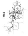
- a known hem folding attachment shown as a whole by A on the front side of the seam forming zone.
- an aiding apparatus for hemming for prefolding the hem into S-shape prior to hemming.
- the aiding apparatus for hemming shown as a whole by B comprises a free roll 19 rotatably axially supported at a suitable position in the slot 17 of the arm 15, a guide ring 13 engaged externally from said free roll 19 and fixed in a manner that its position is adjustable in an axial direction, and a cloth guide apparatus C lying between said free roll 19 and bed 11.
- the cloth guide apparatus C comprises further a.bent resilient wire 27 which is supported at an end of the bell shaped lever 21 with a screw 23 with its bending portion 25 being in spring contact with the end surface of said free roll at the working position, an under guide plate 29 which extends from the vicinity of the spring contact position of said bending portion 25 to the upper surface of the bed with its left side lateral periphery being gradually widened in left oblique direction to the hem feeding direction, an L-shaped base guide 35 which is provided over the under guide plate 29 at a suitable space with the plate 29, a cloth fitting plate 37 which is supported at an end of said bell shaped lever 21 in the same manner as the resilient wire 27 and designed to press over the bending portion of the bent cloth hem, and a cloth edge guide 39 fixed to the right end portion of the base guide 35 and designed to guide the edge of free end of cloth.
- the bell shaped lever 21 is asially supported at its middle part by a movable bracket 31. Between the other end of it and a pin 47 projected from a holder 45 which is position-adjustably settled to a fixed bracket 41 with a screw 43, a spring 49 is applied. By said spring 49, the bell shaped lever 21 is forced to rotate clockwise as shown in Fig. 3A and 3B, and the stoppage of its rotation is made by a pin 51.
- the working rod 55 is set back from the condition shown in Fig. 3B.
- the movable bracket 31 retreats, and the base guide 35 retreats with the cloth edge guide 39 to the non-working position which does not engage with the cloth W.
- the retraction of the movable bracket 31 causes anticlockwise pivoting of the bell shaped lever 21 centering on a pin 52 by engagement with the pin 51, thereby holding up cloth fitting plate 37 over the under guide plate 29 (Fig. 3A).
- the beginning end part of the cloth W is folded into S-letter shape and set to the hem folding attachment A, and the side edge of cloth is applied to the guide ring 13 on the free roll 9, after which the working rod 55 is advanced.
- the base guide 35 and the cloth edge guide 39 advances to the working position, reverse to the above, and the cloth fitting plate 37 presses the bending portion of the cloth W in a manner to cover above the base guide, and also the bending end 25 of the resilient wire 27 lightly presses the cloth W to the side edge surface of the free roll 19 (Fig. 4).
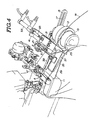
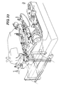
- Fig. 6 and Fig. 7 show another embodiments of this invention.
- the same numerals have been attached to the ones having the same construction as the above embodiments.
- a hem folding attachment A having the cross-sectional shape of U is axially fitted to an end of the slider 62.
- the bracket 64 is fixed and on the bracket 64 the air cylinder 63 and the piston rod 67 of the air cylinder 65 are connected. It is made to reciprocate at right angles to the cloth feeding direction.
- the hem folding attachment A is also connected through a piston rod 69 of the air cylinder 63 and a link 71, and rises and falls by the air cylinder 63. The rising and falling of the hem folding attachment takes place either when the hem folding attachment is at the most advanced position or according to its reciprocation.
- Aiding apparatus B for hemming comprises the guide ring 13, the free roll 19, and a cloth guide apparatus C.
- the free roll 19 is changed over between the working position as shown in Fig. 6 in which the hemming is made and the non-working position receded sideways of the working position.
- the cloth guide apparatus C comprises an under guide plate 29 on which an air pipe 59 is disposed, a base guide 35 which is fitted to a movable bracket 79 which advances and recedes in a direction of crossing at right angles with the feeding direction by means of the air cylinder 77 and furnished with a cloth edge guide 39, and a bent cloth fitting plate 83 which is formed by a curved plate which can reciprocate in a direction crossing at right angles to the feeding direction and can rise and fall, its one side toward the center of the cloth being formed by bending into a J-letter cross-sectional shape along the feeding direction, and being bent further inwardly nearly along the diagonal line connecting a side end of the plate 83 near said hem folding attachment A which enters into the space under said base guide 35 and a lower end of the plate 83 near said free roll 19 which is bent downwardly (Fig.
- a bending end 81 of said plate 83 is formed gradually wider toward the hem folding attachment A, being located on a line connecting the right end of the hem folding attachment A and the left end of the free roll 19.
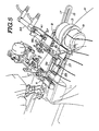
- a turn holder 85 is pivotally fitted to a link 89 fitted to an L-shaped angle plate holder 87 which is supported by a movable bracket 79.
- an end of the wire 93 is connected to a pin 91 at the middle part of the turn holder 85 .
- a collar 101 is fixed to the other projecting end of the wire 93 which extends through the stopper 99 fitted to the end of the working rod 97.
- the bed 11 is also provided at its rear part with a pair of roll comprising a feed roll 109 and a driving roll 111.
- the feed roll 109 is rotatably axially supported by the bed.
- the driving roll 111 is rotatably axially supported at the end of the working rod 117 of the air cylinder 115, and is situated changeable for its position between the working position pushed to the feed roll 109 and the non-working position separated from the feed roll 109 by the advance and retraction of the working rod 117.
- the driving roll 111 connected with the belt 121 is driven by the motor 119.
- the base guide 35, bent cloth fitting plate 83, hem folding attachment A and driving roll 111 are respectively set to the non-working positions and the presser foot 107 is set to the lifted state, under which conditions the hem of cloth is applied over to the free roll 19 and the feed roll 109 and then led under the presser foot 107, and its position setting is made by aligning the cloth end along the guide ring 13 (Fig. 8).
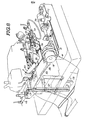
- the base guide 35 is advanced to the working position above the under guide plate 29, and thereafter or simultaneously therewith, the bent cloth fitting plate 83 is advanced and turned over to the working position.
- the cloth W is pushed into a space between the under guide plate 29 and the base guide 35, and the driving roll 111 is advanced to press the hem to the feed roll 109 (Fig. 9).
- the hem holding attachment A advances in an erected state, lies flat on the cloth, at the most advanced position (Fig. 10) retreats by a designed amount from there to the working position and U-shaped folding top of it enters into the space of the S-letter formed bent portion of the cloth.
- the driving roll 111 is driven to rotate by the motor 119 to have the hem circulate by a suitable amount.
- the hem is successively bent in S-letter form (Fig. 14).
- the motor 119 is stopped to stop cloth feeding (Fig. 11).
- the driving roll 111 is detached from the feed roll 109 and the presser foot 107 is lowered to drive the sewing machine.
- hemming is made, and when the hems circulate and the initial hemming portion comes to the free roll 19, the base guide 35 and the bent cloth fitting plate 83 is retracted to the non-working position (Fig. 12).
- the hem folding attachment A is also changed over to the non-working position and the hemming is completed all over the hem of the cloth.
- Lifting and lowering of the presser foot 107, driving or stopping of the motor 119, changeover of base guide, bent cloth fitting plate, and hem folding attachment A, stoppage of sewing machine operation, etc. as above are either effected by the worker's pedal operation or automatically by the known sequence control apparatus.
Landscapes
- Engineering & Computer Science (AREA)
- Textile Engineering (AREA)
- Sewing Machines And Sewing (AREA)
Applications Claiming Priority (4)
| Application Number | Priority Date | Filing Date | Title |
|---|---|---|---|
| JP127179/84 | 1984-08-21 | ||
| JP12717984U JPS6141672U (ja) | 1984-08-21 | 1984-08-21 | ミシンの裾引き補助装置 |
| JP15794684U JPS6321253Y2 (fr) | 1984-10-18 | 1984-10-18 | |
| JP157946/84 | 1984-10-18 |
Publications (2)
| Publication Number | Publication Date |
|---|---|
| EP0177149A1 true EP0177149A1 (fr) | 1986-04-09 |
| EP0177149B1 EP0177149B1 (fr) | 1989-03-15 |
Family
ID=26463194
Family Applications (1)
| Application Number | Title | Priority Date | Filing Date |
|---|---|---|---|
| EP85305852A Expired EP0177149B1 (fr) | 1984-08-21 | 1985-08-16 | Dispositif ourleur |
Country Status (3)
| Country | Link |
|---|---|
| US (1) | US4640206A (fr) |
| EP (1) | EP0177149B1 (fr) |
| DE (1) | DE3568808D1 (fr) |
Cited By (3)
| Publication number | Priority date | Publication date | Assignee | Title |
|---|---|---|---|---|
| GB2209770A (en) * | 1987-09-12 | 1989-05-24 | Hams Corp | Sewing threefold hem in trouser leg |
| EP0460468A1 (fr) * | 1990-05-25 | 1991-12-11 | Texpa-Arbter Maschinenbaugesellschaft mbH | Dispositif pour relier automatiquement le début et la fin d'un ourlet d'un matériau textile circulaire |
| CN112048840A (zh) * | 2020-09-09 | 2020-12-08 | 福恩达机器人(昆山)有限公司 | 一种双层折边定位装置 |
Families Citing this family (6)
| Publication number | Priority date | Publication date | Assignee | Title |
|---|---|---|---|---|
| IT1231885B (it) * | 1987-10-09 | 1992-01-15 | Rockwell Rimoldi Spa | Macchina per cucire polifunzionale. |
| US5622129A (en) * | 1995-10-20 | 1997-04-22 | Jet Sew Technologies, Inc. | Pneumatic tensioning arm for automated sewing machine |
| US5622128A (en) * | 1995-10-20 | 1997-04-22 | Jet Sew Technologies, Inc. | Fabric tensioning system and separator plate for automated sewing machine |
| CN103215761A (zh) * | 2013-04-25 | 2013-07-24 | 张家港华夏帽业有限公司 | 一种双针喇叭吹圆顶制帽夹具 |
| CN106120181A (zh) * | 2016-08-22 | 2016-11-16 | 达利(中国)有限公司 | 一种服装面料气助式下折边卷边器 |
| CN114351393B (zh) * | 2022-01-17 | 2023-09-01 | 安徽东锦高科新材料有限公司 | 一种大尺寸布料收边用布料整平装置 |
Citations (7)
| Publication number | Priority date | Publication date | Assignee | Title |
|---|---|---|---|---|
| US1391876A (en) * | 1918-09-04 | 1921-09-27 | Thomas Carter & Sons Inc | Strip-guide for sewing-machines |
| US1816627A (en) * | 1927-01-04 | 1931-07-28 | Albert H Weis | Elastic strip attachment for sewing machines |
| US3089441A (en) * | 1960-12-09 | 1963-05-14 | Singer Mfg Co | Automatic sewing machines |
| US3786768A (en) * | 1971-10-20 | 1974-01-22 | Union Special Machine Co | Automatic hemming apparatus |
| US3890911A (en) * | 1974-04-11 | 1975-06-24 | Usm Corp | Automatic hemming machine |
| DE2608154A1 (de) * | 1975-02-28 | 1976-09-09 | Lindeman Ab Aino | Verfahren zum befestigen eines taues an den randmaschen eines fischernetzes oder dergleichen sowie vorrichtung zum durchfuehren des verfahrens |
| FR2526819A1 (fr) * | 1982-05-15 | 1983-11-18 | Union Special Gmbh | Dispositif de couture pour la realisation d'un ourlet aveugle sur des pieces en forme de tuyau souple |
Family Cites Families (4)
| Publication number | Priority date | Publication date | Assignee | Title |
|---|---|---|---|---|
| US3752100A (en) * | 1971-10-20 | 1973-08-14 | Union Special Machine Co | Hem folding attachment |
| US3865058A (en) * | 1973-05-30 | 1975-02-11 | Automatech Ind | Method and apparatus for forming and joining hems, particularly on tubular articles |
| IT1002362B (it) * | 1973-12-27 | 1976-05-20 | Virginio Rimoldi E C Spa | Guida apribile per applicare agli indumenti le cinture elastiche ad anello |
| US4055127A (en) * | 1976-03-12 | 1977-10-25 | Union Special Corporation | Hem folding attachment |
-
1985
- 1985-08-16 EP EP85305852A patent/EP0177149B1/fr not_active Expired
- 1985-08-16 DE DE8585305852T patent/DE3568808D1/de not_active Expired
- 1985-08-20 US US06/767,408 patent/US4640206A/en not_active Expired - Fee Related
Patent Citations (7)
| Publication number | Priority date | Publication date | Assignee | Title |
|---|---|---|---|---|
| US1391876A (en) * | 1918-09-04 | 1921-09-27 | Thomas Carter & Sons Inc | Strip-guide for sewing-machines |
| US1816627A (en) * | 1927-01-04 | 1931-07-28 | Albert H Weis | Elastic strip attachment for sewing machines |
| US3089441A (en) * | 1960-12-09 | 1963-05-14 | Singer Mfg Co | Automatic sewing machines |
| US3786768A (en) * | 1971-10-20 | 1974-01-22 | Union Special Machine Co | Automatic hemming apparatus |
| US3890911A (en) * | 1974-04-11 | 1975-06-24 | Usm Corp | Automatic hemming machine |
| DE2608154A1 (de) * | 1975-02-28 | 1976-09-09 | Lindeman Ab Aino | Verfahren zum befestigen eines taues an den randmaschen eines fischernetzes oder dergleichen sowie vorrichtung zum durchfuehren des verfahrens |
| FR2526819A1 (fr) * | 1982-05-15 | 1983-11-18 | Union Special Gmbh | Dispositif de couture pour la realisation d'un ourlet aveugle sur des pieces en forme de tuyau souple |
Cited By (6)
| Publication number | Priority date | Publication date | Assignee | Title |
|---|---|---|---|---|
| GB2209770A (en) * | 1987-09-12 | 1989-05-24 | Hams Corp | Sewing threefold hem in trouser leg |
| US4947771A (en) * | 1987-09-12 | 1990-08-14 | Hams Corporation | Sewing machine |
| GB2209770B (en) * | 1987-09-12 | 1991-08-21 | Hams Corp | Sewing machine |
| EP0460468A1 (fr) * | 1990-05-25 | 1991-12-11 | Texpa-Arbter Maschinenbaugesellschaft mbH | Dispositif pour relier automatiquement le début et la fin d'un ourlet d'un matériau textile circulaire |
| US5271347A (en) * | 1990-05-25 | 1993-12-21 | Francisco Carreras Fontcuberta | Process and associated apparatus for joining automatically the beginning and the end of a hem in a circular textile material |
| CN112048840A (zh) * | 2020-09-09 | 2020-12-08 | 福恩达机器人(昆山)有限公司 | 一种双层折边定位装置 |
Also Published As
| Publication number | Publication date |
|---|---|
| DE3568808D1 (en) | 1989-04-20 |
| EP0177149B1 (fr) | 1989-03-15 |
| US4640206A (en) | 1987-02-03 |
Similar Documents
| Publication | Publication Date | Title |
|---|---|---|
| US4098204A (en) | Apparatus for stretch-sewing a hem in tubular fabric | |
| US4114544A (en) | Apparatus for forming loops on a garment | |
| EP0177149B1 (fr) | Dispositif ourleur | |
| JPS58138480A (ja) | 衣服の筒状部分の自由端を自動的に縁縫いする装置 | |
| US4800830A (en) | Hemmer seamer assembly | |
| KR100985685B1 (ko) | 자수 미싱 | |
| US5131336A (en) | Waist part cloth guiding device for a sewing machine | |
| CN111663253B (zh) | 圆状物面料的卷边缝制缝纫机 | |
| HU180824B (en) | Shoe industrial sewing-machine for compacting cut pieces particularly moccasin ones by means of flange seam | |
| JPH08257276A (ja) | ミシン装置 | |
| US3481292A (en) | Hemming device | |
| CN210596535U (zh) | 一种用于缝合压线机的翻边机构 | |
| US4922842A (en) | Hemmer seamer assembly | |
| CN105133200B (zh) | 一种用于鞋舌加工的织带机 | |
| JPH0714364B2 (ja) | スライドフアスナ−端部への保護テ−プの供給,縫着方法および装置 | |
| US4972787A (en) | Hemmer seamer assembly | |
| US4896619A (en) | Hemmer seamer assembly | |
| US4903623A (en) | Hemmer seamer assembly | |
| US3322081A (en) | Material stitching and guiding machine | |
| US5199364A (en) | Sewing machine having two bordering guides movable vertically and horizontally respectively, for applying ribbon like trimmings to a work piece | |
| US2256792A (en) | Apparatus for making trimmings | |
| US2170948A (en) | Sewing machine | |
| JPS6321253Y2 (fr) | ||
| US4722289A (en) | Sewing machine | |
| US2863407A (en) | Spiral sewing machine |
Legal Events
| Date | Code | Title | Description |
|---|---|---|---|
| PUAI | Public reference made under article 153(3) epc to a published international application that has entered the european phase |
Free format text: ORIGINAL CODE: 0009012 |
|
| AK | Designated contracting states |
Kind code of ref document: A1 Designated state(s): DE FR GB IT |
|
| 17P | Request for examination filed |
Effective date: 19860908 |
|
| 17Q | First examination report despatched |
Effective date: 19871202 |
|
| GRAA | (expected) grant |
Free format text: ORIGINAL CODE: 0009210 |
|
| AK | Designated contracting states |
Kind code of ref document: B1 Designated state(s): DE FR GB IT |
|
| ITF | It: translation for a ep patent filed | ||
| REF | Corresponds to: |
Ref document number: 3568808 Country of ref document: DE Date of ref document: 19890420 |
|
| ET | Fr: translation filed | ||
| PLBE | No opposition filed within time limit |
Free format text: ORIGINAL CODE: 0009261 |
|
| STAA | Information on the status of an ep patent application or granted ep patent |
Free format text: STATUS: NO OPPOSITION FILED WITHIN TIME LIMIT |
|
| 26N | No opposition filed | ||
| ITTA | It: last paid annual fee | ||
| PGFP | Annual fee paid to national office [announced via postgrant information from national office to epo] |
Ref country code: FR Payment date: 19940615 Year of fee payment: 10 |
|
| PGFP | Annual fee paid to national office [announced via postgrant information from national office to epo] |
Ref country code: GB Payment date: 19940804 Year of fee payment: 10 |
|
| PGFP | Annual fee paid to national office [announced via postgrant information from national office to epo] |
Ref country code: DE Payment date: 19940930 Year of fee payment: 10 |
|
| PG25 | Lapsed in a contracting state [announced via postgrant information from national office to epo] |
Ref country code: GB Effective date: 19950816 |
|
| GBPC | Gb: european patent ceased through non-payment of renewal fee |
Effective date: 19950816 |
|
| PG25 | Lapsed in a contracting state [announced via postgrant information from national office to epo] |
Ref country code: FR Effective date: 19960430 |
|
| PG25 | Lapsed in a contracting state [announced via postgrant information from national office to epo] |
Ref country code: DE Effective date: 19960501 |
|
| REG | Reference to a national code |
Ref country code: FR Ref legal event code: ST |