EP0177238A1 - Courroie à maillons - Google Patents
Courroie à maillons Download PDFInfo
- Publication number
- EP0177238A1 EP0177238A1 EP85306750A EP85306750A EP0177238A1 EP 0177238 A1 EP0177238 A1 EP 0177238A1 EP 85306750 A EP85306750 A EP 85306750A EP 85306750 A EP85306750 A EP 85306750A EP 0177238 A1 EP0177238 A1 EP 0177238A1
- Authority
- EP
- European Patent Office
- Prior art keywords
- links
- belt
- pulley
- block
- flanges
- Prior art date
- Legal status (The legal status is an assumption and is not a legal conclusion. Google has not performed a legal analysis and makes no representation as to the accuracy of the status listed.)
- Granted
Links
Images
Classifications
-
- F—MECHANICAL ENGINEERING; LIGHTING; HEATING; WEAPONS; BLASTING
- F16—ENGINEERING ELEMENTS AND UNITS; GENERAL MEASURES FOR PRODUCING AND MAINTAINING EFFECTIVE FUNCTIONING OF MACHINES OR INSTALLATIONS; THERMAL INSULATION IN GENERAL
- F16G—BELTS, CABLES, OR ROPES, PREDOMINANTLY USED FOR DRIVING PURPOSES; CHAINS; FITTINGS PREDOMINANTLY USED THEREFOR
- F16G5/00—V-belts, i.e. belts of tapered cross-section
- F16G5/16—V-belts, i.e. belts of tapered cross-section consisting of several parts
- F16G5/18—V-belts, i.e. belts of tapered cross-section consisting of several parts in the form of links
-
- F—MECHANICAL ENGINEERING; LIGHTING; HEATING; WEAPONS; BLASTING
- F16—ENGINEERING ELEMENTS AND UNITS; GENERAL MEASURES FOR PRODUCING AND MAINTAINING EFFECTIVE FUNCTIONING OF MACHINES OR INSTALLATIONS; THERMAL INSULATION IN GENERAL
- F16G—BELTS, CABLES, OR ROPES, PREDOMINANTLY USED FOR DRIVING PURPOSES; CHAINS; FITTINGS PREDOMINANTLY USED THEREFOR
- F16G5/00—V-belts, i.e. belts of tapered cross-section
- F16G5/16—V-belts, i.e. belts of tapered cross-section consisting of several parts
Definitions
- Variable pulley transmissions for transferring torque from an input or drive shaft to an output or driven shaft have been used for some time.
- a first pulley constructed of a pair of flanges is mounted on the input shaft such that at least one of its flanges is axially movable with respect to its other flange.
- a second, similarly constructed and adjustable pulley is mounted on the output shaft.
- a flexible belt connects the two pulleys to transfer torque therebetween when the input shaft is driven.
- the effective diameter of one pulley is changed and, simultaneously, the effective diameter of the other pulley is changed in the opposite direction, the drive ratio between the input and output shafts is adjusted in a smooth, continuous manner.
- Flexible metal belts for use with CVTs are generally of two varieties, those referred to as "push” belts and those referred to as “pull” belts.
- An example of a push belt is described in Van Doorne et al U.S. patent No. 3,720,113 and an example of a pull belt is described in Cole, Jr. et al U.S. patent No. 4,313,730.
- the Van Doorne et al belt comprises an endless carrier constructed of a plurality of nested metal bands and an endless array of load blocks longitudinally movable along the carrier. Each block has edge surfaces frictionally engaging the pulley flanges of a pulley transmission to transmit torque between the pulleys.
- et al utilizes an endless chain as the carrier, the sets of links of which are pivotably interconnected by pivot means, shown as round pins.
- pivot means shown as round pins.
- Generally trapezoidal (when viewed from the front) load blocks encircle the links; however the load blocks are constrained against longitudinal movement along the chain by the pivot means.
- the push belt as described is relatively expensive to manufacture because the nested carrier bands are precisely matched to each other. Such a belt must be installed and/or replaced as a complete, endless loop, and thus disassembly of parts of the pulley transmission is required, not only for the initial assembly, but also for replacement due to failure of one or more load blocks or one or more of its carrier bands.
- the pull belt offers a less expensive alternative to the push belt. No precise matching of carrier parts is required.
- the belt can be assembled with a finite length, positioned around the pulleys, and the ends of the belt then are connected by a pivot member to make an endless belt. Thus disassembly of the pulleys is not required either for initial installation or for replacement of a belt.
- Load blocks have a tendency to rock or tilt with respect to the carrier, especially when entering the pulley.
- the edge surfaces may engage the pulley flanges slightly askew to a radial line.
- the block's "window” or “windows”, i.e., the opening or openings in which the carrier is located are made with _square defining edges, as is customary when the blocks are stamped from sheet metal, the tilting of the blocks causes the top and/or the bottom window defining edges to dig into and damage the carrier, thus weakening the carrier and seriously affecting its ability to transmit torque. The damage to the carrier leads to its premature failure.
- One approach to solving this problem and not yet proven is to make the top and bottom window defining surfaces from front to back slightly round or arcuate. This procedure adds to the manufacturing costs of the belt.
- Load blocks for use with either carrier system have been constructed with generally flat, planar, pulley- flange-engaging edge surfaces. These surfaces are, at times, joined to the top and bottom surfaces of the blocks by curved surfaces of small radii which have no effect on block-pulley contact. Load blocks, during their torque transmitting operation, are pulled inwardly of each pulley and are thus subjected to transversely applied compressive loads which unduly stresses the blocks and which can lead to their failure.
- a modified load block is used to construct a CVT belt.
- the invention will be described with reference to a pull type belt such as taught, by way of example, in Cole et al, previously referred to, and the complete belt assembly will be referred to as a "chain-belt.”
- the load block used for descriptive purposes is a multi-windowed block, as described and claimed in a co-pending application of Cole et al, Serial No. 485,781, filed April 4, 1983. It will become apparent that the load block of this invention has broad applications, and is not limited to environments such as the Cole et al references.
- the pulley- flange-engaging edge surfaces of each block are "crowned” or rounded, or curved, as contrasted to conventional flat surfaces generally provided on the block edges.
- “Crowned” means that the block edge surfaces, which engage the pulley flanges, are curved or arcuate along a substantial portion of their length. They present a convex surface to the pulley flanges.
- crowning the flange-contacting edge surfaces of the blocks produces an initial point contact with the adjacent portions of the pulley flanges, but because of the side-to-side compressive load on the blocks, in reality the crowned block surfaces are distorted and thus contact the flange surfaces over a significant area which is much greater than the initial point contact.
- the undesirable, initial tilting or rocking of the blocks with respect to the pulley flanges can be at least partially, if not entirely, eliminated by selecting a particular location of the points on the block sides which initially contact the pulley. It has been found that an effective location of the initial block contact point on the edge surfaces lies on a horizontal centerline of the block's window or windows.
- the center of the curve of the block's edges lies on a line intersecting the initial contact point and defining with the centerline an angle substantially that of the angle of the pulley flange.
- the radius dimension of the crowned edge surface is approximately five times the width of the block, or more, i.e., a dimension far in excess of any other dimension of the block.
- the major portion of the block's side edges are crowned; in another form of block, only a substantial portion of the side edges are crowned with the remainder cut away, so as not to contact the pulley flanges.
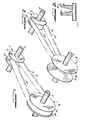
- Figs. 1 and 2 of the drawings illustrate a continuously variable transmission (CVT) in an underdrive and an overdrive ratios.
- a first pulley 11 is connected to a shaft 13 and a second pulley 15 is connected to a shaft 17.
- One shaft is a drive shaft and the other shaft is a driven shaft.
- a continuous, flexible belt 19 interconnects the pulleys 11 and 15.
- flange 21 of pulley 11 is made axially movable with respect to flange 23, and correspondingly, flange 27 of pulley 15 is axially movable with respect to flange 25.
- both flanges of a pulley may be axially movable with respect to each other, but generally this is not necessary to effect the changes in the drive ratios between the pulleys and their respective shafts.
- the flange angle that is, the angle defined by a line on the flange surface which intersects a line perpendicular to the pulley shaft, is designated O in Fig. 2A.
- the flange angle is the same for each pulley 11 and 15.
- Various types of controls may be used to effect the changes in drive ratio but these are not within the purview of this invention and need no further reference.
- the side surfaces or edges 29 of the continuous, flexible belt 19 frictionally engage the pulley flanges when transmitting torque from the drive pulley to the driven pulley.
- a chain-belt As mentioned previously, one type of drive belt to interconnect the pulleys is referred to as a chain-belt.
- This invention is directed to an improvement in this type of belt, although the inventive concept can be used with other types of flexible belts using drive blocks to frictionally engage the flanges of the pulleys of a pulley transmission.
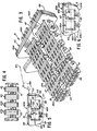
- Figs. 3 and 4 illustrate various features of a chain-belt 31 (only a segment of a complete, endless belt being shown) constructed according to this invention.
- the chain-belt 31 has a carrier comprising metal links 33 economically stamped from sheet metal and arranged in sets 35 and 37 which are interleaved with one another.
- a "set" of links is those links which are grouped transversely together.
- each set 35 and 37 includes two subsets 35A, 35B and 37A, 37B, spaced apart from each other for reasons that will become apparent.
- Each link 33 defines a pair of spaced apertures 39, each aperture being adjacent to an end of the link, and the apertures in a set of links are transversely aligned with one another.
- the apertures at one end of a set of links are transversely aligned with those at one end in the interleaved set, so that a pivot means 41 can be passed therethrough.
- the pivot means defines an axis about which the next adjacent links pivot and in illustrated as a pin and rocker joint. A preferred form of pin and rocker is described and claimed in a copending application of Cole, Serial No.
- pivot means are each illustrated as a pin and rocker, it should be understood that other forms of pivot means, such as the conventional round pin, can be used without departing from the invention.
- a plurality of load or drive blocks 43 are used.
- the load blocks 43 illustrated are each constructed of a plurality of plates 43A which can economically be stamped from sheet metal. They can be of one piece construction if desired.
- Fig. 5 illustrates in more detail one form of load block plate 43A constructed according to this invention.
- a load block is positioned to encircle a set of links between pivot means and the block defines, in the illustrated form, a pair of centrally located windows 45A and 45B separated by a strut 47.
- Each load block has a pair of side or edge surfaces 49 for engaging the pulley flanges.
- Blocks are generally trapezoidal in shape when viewed from the front as illustrated in Fig. 5, and are also sometimes referred to as being generally V-shaped.
- the edge surfaces 49 of the block are joined to the top and bottom surfaces 51 and 53 by curved surfaces 55 and 57 of very small radii to avoid sharp edges.
- one problem of conventional chain-belts is the tilting or rocking of load blocks when they enter a pulley, sometimes causing at least one edge of the window to dig into the chain links, weakening the links and ultimately causing failure of the chain-belt.
- the side or edge surfaces 49 of the blocks 43 are "crowned.”
- the initial contact points of the side edges of the blocks and the pulleys are preferably located with reference to a horizontal line 59 through the windows of the blocks.
- “Crowned” means to convexly curve the surfaces 49, with the radius of curvature thereof of a length far in excess of any other dimension of the block itself.
- the radius of curvature can be of a magnitude far in excess of the width (that dimension of the block from side-to-side and across the block from points 65 to 65 as shown in Fig. 5) dimension of the block. Values in the range of one-half of a reference value to five times a reference value are considered in the same magnitude as the reference value. Accordingly used herein and in the appended claims, a magnitude greater is from five to fifty times (or more) the reference value.
- a radius of curvature of 8 inches for blocks 1.25 inches wide has been successfully tested.
- the pulley-engaging surfaces are curved between the surfaces 55 and 57, but are not curved along the thickness of the block, i.e., from front 61 to back 63.
- the initial pulley contact points 65 preferably are located on a horizontal line 59 through the windows 45A, 45B.
- the center 67 of the arc defining the left edge 49 is located on a line 69 intersecting the edge 49 and the line 59 at the point 65 at the block edge, and likewise, but not shown, the center 67 of the arc defining the right edge 49 is located at the intersection of lines 69 and 59 at the right hand point 65 on the block edge 49.
- the line 69 and the centerline 59 define angle 0 which is equal to the flange angle as shown in Fig. 2, while the center 67 is shown for left-hand surface 49, a similar center 67 is used to generate right-hand surface 49.
- the crowned edge surfaces 49A do not extend completely between the surfaces 55A and 57A.
- surfaces 49A are relieved to form the set-back surfaces 71, either during formation of the plates, after being formed, or after the parts are assembled.
- Surfaces 71 are set-back so they do not contact the pulley flanges.
- the upper surfaces of the blocks can be such as to not contact the pulley flanges.
- the links, pivot means and blocks are preferably made of steel and the links and pivot means are generally hardened.
- the load or drive blocks can be of one piece construction or laminated of a plurality of stamped elements. They may also be produced by powdered metal techniques.
- the load blocks in a chain-belt constructed according to this invention have shown significantly improved life than straight sided blocks under similar test conditions.
Landscapes
- Engineering & Computer Science (AREA)
- General Engineering & Computer Science (AREA)
- Mechanical Engineering (AREA)
- Transmissions By Endless Flexible Members (AREA)
- Devices For Conveying Motion By Means Of Endless Flexible Members (AREA)
Applications Claiming Priority (2)
| Application Number | Priority Date | Filing Date | Title |
|---|---|---|---|
| US06/656,282 US4622025A (en) | 1984-10-01 | 1984-10-01 | Chain-belt |
| US656282 | 1984-10-01 |
Publications (2)
| Publication Number | Publication Date |
|---|---|
| EP0177238A1 true EP0177238A1 (fr) | 1986-04-09 |
| EP0177238B1 EP0177238B1 (fr) | 1988-06-08 |
Family
ID=24632399
Family Applications (1)
| Application Number | Title | Priority Date | Filing Date |
|---|---|---|---|
| EP85306750A Expired EP0177238B1 (fr) | 1984-10-01 | 1985-09-23 | Courroie à maillons |
Country Status (5)
| Country | Link |
|---|---|
| US (1) | US4622025A (fr) |
| EP (1) | EP0177238B1 (fr) |
| JP (1) | JPS6184436A (fr) |
| CA (1) | CA1255119A (fr) |
| DE (1) | DE3563252D1 (fr) |
Cited By (3)
| Publication number | Priority date | Publication date | Assignee | Title |
|---|---|---|---|---|
| EP0257646A3 (en) * | 1986-08-28 | 1988-06-29 | Bando Chemical Industries, Ltd. | V belt with blocks |
| EP1134452A3 (fr) * | 2000-02-24 | 2001-10-04 | Borg-Warner Automotive K. K. | Element de liaison pour une chaíne de transmission à variation continue avec boulon étagé |
| WO2016082133A1 (fr) * | 2014-11-26 | 2016-06-02 | GM Global Technology Operations LLC | Transmission à variation continue |
Families Citing this family (23)
| Publication number | Priority date | Publication date | Assignee | Title |
|---|---|---|---|---|
| GB2190169B (en) * | 1986-04-30 | 1989-11-29 | Nissan Motor | Power transmission belt |
| JPS62258240A (ja) * | 1986-04-30 | 1987-11-10 | Nissan Motor Co Ltd | Vベルト |
| JPH0781613B2 (ja) * | 1986-11-04 | 1995-09-06 | アイシン・エィ・ダブリュ株式会社 | 駆動用無端ベルト |
| JPS63303240A (ja) * | 1987-05-29 | 1988-12-09 | Aisin Warner Ltd | 伝動用無端ベルト |
| US4871344A (en) * | 1987-09-24 | 1989-10-03 | Toyota Jidosha Kabushiki Kaisha | Power transmission chain belt |
| JPH01238767A (ja) * | 1987-10-26 | 1989-09-22 | Toyota Motor Corp | ベルト式無段変速機用プーリ |
| US5073154A (en) * | 1987-10-28 | 1991-12-17 | Borg-Warner Corporation | Chain-belt |
| US5009631A (en) * | 1987-10-28 | 1991-04-23 | Borg-Warner Automotive, Inc. | CVT chain-belt |
| US4911682A (en) * | 1987-10-28 | 1990-03-27 | Borg-Warner Automotive, Inc. | Cambered pin CVT chain belt |
| JPH0276944A (ja) * | 1988-09-10 | 1990-03-16 | Daido Kogyo Co Ltd | 動力伝達装置 |
| US5167587A (en) * | 1991-06-24 | 1992-12-01 | Borg-Warner Automotive Transmission & Engine Components Corporation | Chain-belt |
| US5061226A (en) * | 1990-03-20 | 1991-10-29 | Borg-Warner Automotive Transmission & Engine Components Corporation | Chain-belt |
| US5090948A (en) * | 1990-03-20 | 1992-02-25 | Borg-Warner Automotive Transmission & Engine Components Corporation | Chain belt power transmission |
| US5263903A (en) * | 1990-03-20 | 1993-11-23 | Borg-Warner Automotive Transmission & Engine Components Corporation | Chain-belt |
| US4993999A (en) * | 1990-03-20 | 1991-02-19 | Borg-Warner Automotive, Inc. | Chain-belt |
| US5147251A (en) * | 1991-06-13 | 1992-09-15 | Borg-Warner Automotive Transmission & Engine Components Corporation | Chain design |
| JP3692837B2 (ja) | 1999-06-22 | 2005-09-07 | 日産自動車株式会社 | ベルト式無段変速機 |
| CN1190607C (zh) * | 1999-08-19 | 2005-02-23 | 西南师范大学 | 组合式传动带 |
| NL1027685C2 (nl) * | 2004-12-08 | 2006-06-09 | Bosch Gmbh Robert | Drijfriem voor een transmissie met gebombeerde poelieschijven. |
| JP4887371B2 (ja) * | 2005-11-08 | 2012-02-29 | ロベルト ボッシュ ゲゼルシャフト ミト ベシュレンクテル ハフツング | プーリおよび駆動ベルトを持つ変速機 |
| DE112012006666T5 (de) * | 2012-07-06 | 2015-03-19 | Honda Motor Co., Ltd. | Element für metallischen Riemen |
| WO2014019699A1 (fr) * | 2012-08-03 | 2014-02-06 | Iwis Motorsysteme Gmbh & Co. Kg | Articulation destinée à des chaînes à douilles ou à rouleaux et réduisant le frottement et l'usure |
| JP6190743B2 (ja) * | 2014-03-24 | 2017-08-30 | 本田技研工業株式会社 | 無段変速機のリンクプレートチェーン |
Citations (8)
| Publication number | Priority date | Publication date | Assignee | Title |
|---|---|---|---|---|
| FR743438A (fr) * | 1933-03-29 | |||
| US3016755A (en) * | 1958-12-20 | 1962-01-16 | Reimers Getriebe Kg | Link chain for infinitely variable pulley gear transmissions |
| DE1960350A1 (de) * | 1969-12-02 | 1971-06-09 | Volkswagenwerk Ag | Keilriemen fuer Getriebe mit stufenlos veraenderbarem UEbersetzungsverhaeltnis |
| US3720113A (en) * | 1971-04-06 | 1973-03-13 | Doorne H Van | Flexible continuous power transmission means |
| GB2071806A (en) * | 1980-03-17 | 1981-09-23 | Borg Warner | Metal chain belt |
| EP0109202A1 (fr) * | 1982-11-17 | 1984-05-23 | Borg-Warner Corporation | Chaîne de transmission de puissance |
| FR2540953A1 (fr) * | 1983-02-15 | 1984-08-17 | Renault | Cavalier de courroie a maillons poussants |
| EP0125751A1 (fr) * | 1983-04-18 | 1984-11-21 | Borg-Warner Corporation | Chaîne-courroie |
Family Cites Families (6)
| Publication number | Priority date | Publication date | Assignee | Title |
|---|---|---|---|---|
| US3138034A (en) * | 1960-06-11 | 1964-06-23 | Reimers Getriebe Kg | Link chain for transmitting power by friction for infinitely variable gears |
| DE1294130B (de) * | 1964-11-25 | 1969-04-30 | Piv Antrieb Reimers Kg Werner | Laschenkette fuer stufenlos verstellbare Kegelscheibenumschlingungsgetriebe |
| CH451616A (de) * | 1965-07-29 | 1968-05-15 | Reimers Getriebe Ag | Verfahren zur Herstellung eines Zugmittelstranges aus einstückigen metallischen Kettengliedern für Kegelscheibenumschlingungsgetriebe und nach dem Verfahren hergestellter Zugmittelstrang |
| JPS5249019U (fr) * | 1975-10-03 | 1977-04-07 | ||
| DE2949061A1 (de) * | 1979-12-06 | 1981-06-11 | Helmut 3006 Burgwedel Körner | Gliederkette |
| DE3413384C2 (de) * | 1984-04-10 | 1986-05-07 | P.I.V. Antrieb Werner Reimers GmbH & Co KG, 6380 Bad Homburg | Laschenkette für stufenlos verstellbare Kegelscheibengetriebe |
-
1984
- 1984-10-01 US US06/656,282 patent/US4622025A/en not_active Expired - Fee Related
-
1985
- 1985-09-23 EP EP85306750A patent/EP0177238B1/fr not_active Expired
- 1985-09-23 DE DE8585306750T patent/DE3563252D1/de not_active Expired
- 1985-10-01 CA CA000491950A patent/CA1255119A/fr not_active Expired
- 1985-10-01 JP JP60219004A patent/JPS6184436A/ja active Pending
Patent Citations (8)
| Publication number | Priority date | Publication date | Assignee | Title |
|---|---|---|---|---|
| FR743438A (fr) * | 1933-03-29 | |||
| US3016755A (en) * | 1958-12-20 | 1962-01-16 | Reimers Getriebe Kg | Link chain for infinitely variable pulley gear transmissions |
| DE1960350A1 (de) * | 1969-12-02 | 1971-06-09 | Volkswagenwerk Ag | Keilriemen fuer Getriebe mit stufenlos veraenderbarem UEbersetzungsverhaeltnis |
| US3720113A (en) * | 1971-04-06 | 1973-03-13 | Doorne H Van | Flexible continuous power transmission means |
| GB2071806A (en) * | 1980-03-17 | 1981-09-23 | Borg Warner | Metal chain belt |
| EP0109202A1 (fr) * | 1982-11-17 | 1984-05-23 | Borg-Warner Corporation | Chaîne de transmission de puissance |
| FR2540953A1 (fr) * | 1983-02-15 | 1984-08-17 | Renault | Cavalier de courroie a maillons poussants |
| EP0125751A1 (fr) * | 1983-04-18 | 1984-11-21 | Borg-Warner Corporation | Chaîne-courroie |
Cited By (5)
| Publication number | Priority date | Publication date | Assignee | Title |
|---|---|---|---|---|
| EP0257646A3 (en) * | 1986-08-28 | 1988-06-29 | Bando Chemical Industries, Ltd. | V belt with blocks |
| US4813920A (en) * | 1986-08-28 | 1989-03-21 | Bando Chemical Industries, Ltd. | V belt with blocks |
| EP1134452A3 (fr) * | 2000-02-24 | 2001-10-04 | Borg-Warner Automotive K. K. | Element de liaison pour une chaíne de transmission à variation continue avec boulon étagé |
| WO2016082133A1 (fr) * | 2014-11-26 | 2016-06-02 | GM Global Technology Operations LLC | Transmission à variation continue |
| US10428914B2 (en) | 2014-11-26 | 2019-10-01 | GM Global Technology Operations LLC | Continuously variable transmission |
Also Published As
| Publication number | Publication date |
|---|---|
| US4622025A (en) | 1986-11-11 |
| DE3563252D1 (en) | 1988-07-14 |
| CA1255119A (fr) | 1989-06-06 |
| EP0177238B1 (fr) | 1988-06-08 |
| JPS6184436A (ja) | 1986-04-30 |
Similar Documents
| Publication | Publication Date | Title |
|---|---|---|
| US4622025A (en) | Chain-belt | |
| EP0127266B1 (fr) | Courroie de transmission à maillons | |
| EP0127270B1 (fr) | Courroie de transmission à maillons | |
| US4507106A (en) | Power transmission chain | |
| EP0125751B1 (fr) | Chaîne-courroie | |
| US4708701A (en) | Chain-belt | |
| US4580999A (en) | Metal chain-belt | |
| EP0127255B1 (fr) | Courroie de transmission à maillons | |
| US4386922A (en) | Power transmission chain belt | |
| US4569671A (en) | Metal chain-belt | |
| US4581000A (en) | Load block for chain-belt | |
| US5007883A (en) | Chain-belt | |
| US4553953A (en) | Chain-belt | |
| US4692130A (en) | Load block for chain-belt | |
| US5026332A (en) | Chain-belt | |
| US5090948A (en) | Chain belt power transmission | |
| CA2062532C (fr) | Courroie articulee | |
| EP0448210B1 (fr) | Courroie à maillons | |
| US4943266A (en) | Metal chain belt | |
| EP0183428B1 (fr) | Courroie métallique à maillons | |
| US20020151399A1 (en) | Compression belt for CVT having a crowned strut edge wherein the radius is determined by the maximum allowable contact stress and is located so that the contact point remains close to the rocking radius of the struts |
Legal Events
| Date | Code | Title | Description |
|---|---|---|---|
| PUAI | Public reference made under article 153(3) epc to a published international application that has entered the european phase |
Free format text: ORIGINAL CODE: 0009012 |
|
| AK | Designated contracting states |
Kind code of ref document: A1 Designated state(s): DE FR GB NL |
|
| 17P | Request for examination filed |
Effective date: 19860527 |
|
| 17Q | First examination report despatched |
Effective date: 19861215 |
|
| GRAA | (expected) grant |
Free format text: ORIGINAL CODE: 0009210 |
|
| AK | Designated contracting states |
Kind code of ref document: B1 Designated state(s): DE FR GB NL |
|
| REF | Corresponds to: |
Ref document number: 3563252 Country of ref document: DE Date of ref document: 19880714 |
|
| ET | Fr: translation filed | ||
| PLBE | No opposition filed within time limit |
Free format text: ORIGINAL CODE: 0009261 |
|
| STAA | Information on the status of an ep patent application or granted ep patent |
Free format text: STATUS: NO OPPOSITION FILED WITHIN TIME LIMIT |
|
| 26N | No opposition filed | ||
| PGFP | Annual fee paid to national office [announced via postgrant information from national office to epo] |
Ref country code: GB Payment date: 19920810 Year of fee payment: 8 |
|
| PGFP | Annual fee paid to national office [announced via postgrant information from national office to epo] |
Ref country code: FR Payment date: 19920917 Year of fee payment: 8 |
|
| PGFP | Annual fee paid to national office [announced via postgrant information from national office to epo] |
Ref country code: DE Payment date: 19920925 Year of fee payment: 8 |
|
| PGFP | Annual fee paid to national office [announced via postgrant information from national office to epo] |
Ref country code: NL Payment date: 19920930 Year of fee payment: 8 |
|
| PG25 | Lapsed in a contracting state [announced via postgrant information from national office to epo] |
Ref country code: GB Effective date: 19930923 |
|
| PG25 | Lapsed in a contracting state [announced via postgrant information from national office to epo] |
Ref country code: NL Effective date: 19940401 |
|
| NLV4 | Nl: lapsed or anulled due to non-payment of the annual fee | ||
| GBPC | Gb: european patent ceased through non-payment of renewal fee |
Effective date: 19930923 |
|
| PG25 | Lapsed in a contracting state [announced via postgrant information from national office to epo] |
Ref country code: FR Free format text: LAPSE BECAUSE OF NON-PAYMENT OF DUE FEES Effective date: 19940531 |
|
| PG25 | Lapsed in a contracting state [announced via postgrant information from national office to epo] |
Ref country code: DE Effective date: 19940601 |
|
| REG | Reference to a national code |
Ref country code: FR Ref legal event code: ST |