EP0177254A2 - Verfahren und Vorrichtung zum Schützen eines vorgeformten, vorragenden Anhängsels während des Kunststoffgiessens - Google Patents
Verfahren und Vorrichtung zum Schützen eines vorgeformten, vorragenden Anhängsels während des Kunststoffgiessens Download PDFInfo
- Publication number
- EP0177254A2 EP0177254A2 EP85306807A EP85306807A EP0177254A2 EP 0177254 A2 EP0177254 A2 EP 0177254A2 EP 85306807 A EP85306807 A EP 85306807A EP 85306807 A EP85306807 A EP 85306807A EP 0177254 A2 EP0177254 A2 EP 0177254A2
- Authority
- EP
- European Patent Office
- Prior art keywords
- mold core
- box
- tubing
- mold
- molded product
- Prior art date
- Legal status (The legal status is an assumption and is not a legal conclusion. Google has not performed a legal analysis and makes no representation as to the accuracy of the status listed.)
- Withdrawn
Links
Images


Classifications
-
- B—PERFORMING OPERATIONS; TRANSPORTING
- B29—WORKING OF PLASTICS; WORKING OF SUBSTANCES IN A PLASTIC STATE IN GENERAL
- B29C—SHAPING OR JOINING OF PLASTICS; SHAPING OF MATERIAL IN A PLASTIC STATE, NOT OTHERWISE PROVIDED FOR; AFTER-TREATMENT OF THE SHAPED PRODUCTS, e.g. REPAIRING
- B29C45/00—Injection moulding, i.e. forcing the required volume of moulding material through a nozzle into a closed mould; Apparatus therefor
- B29C45/14—Injection moulding, i.e. forcing the required volume of moulding material through a nozzle into a closed mould; Apparatus therefor incorporating preformed parts or layers, e.g. injection moulding around inserts or for coating articles
-
- A—HUMAN NECESSITIES
- A61—MEDICAL OR VETERINARY SCIENCE; HYGIENE
- A61F—FILTERS IMPLANTABLE INTO BLOOD VESSELS; PROSTHESES; DEVICES PROVIDING PATENCY TO, OR PREVENTING COLLAPSING OF, TUBULAR STRUCTURES OF THE BODY, e.g. STENTS; ORTHOPAEDIC, NURSING OR CONTRACEPTIVE DEVICES; FOMENTATION; TREATMENT OR PROTECTION OF EYES OR EARS; BANDAGES, DRESSINGS OR ABSORBENT PADS; FIRST-AID KITS
- A61F6/00—Contraceptive devices; Pessaries; Applicators therefor
- A61F6/02—Contraceptive devices; Pessaries; Applicators therefor for use by males
- A61F6/04—Condoms, sheaths or the like, e.g. combined with devices protecting against contagion
-
- B—PERFORMING OPERATIONS; TRANSPORTING
- B29—WORKING OF PLASTICS; WORKING OF SUBSTANCES IN A PLASTIC STATE IN GENERAL
- B29C—SHAPING OR JOINING OF PLASTICS; SHAPING OF MATERIAL IN A PLASTIC STATE, NOT OTHERWISE PROVIDED FOR; AFTER-TREATMENT OF THE SHAPED PRODUCTS, e.g. REPAIRING
- B29C41/00—Shaping by coating a mould, core or other substrate, i.e. by depositing material and stripping-off the shaped article; Apparatus therefor
- B29C41/02—Shaping by coating a mould, core or other substrate, i.e. by depositing material and stripping-off the shaped article; Apparatus therefor for making articles of definite length, i.e. discrete articles
- B29C41/20—Shaping by coating a mould, core or other substrate, i.e. by depositing material and stripping-off the shaped article; Apparatus therefor for making articles of definite length, i.e. discrete articles incorporating preformed parts or layers, e.g. moulding inserts or for coating articles
-
- B—PERFORMING OPERATIONS; TRANSPORTING
- B29—WORKING OF PLASTICS; WORKING OF SUBSTANCES IN A PLASTIC STATE IN GENERAL
- B29C—SHAPING OR JOINING OF PLASTICS; SHAPING OF MATERIAL IN A PLASTIC STATE, NOT OTHERWISE PROVIDED FOR; AFTER-TREATMENT OF THE SHAPED PRODUCTS, e.g. REPAIRING
- B29C70/00—Shaping composites, i.e. plastics material comprising reinforcements, fillers or preformed parts, e.g. inserts
- B29C70/68—Shaping composites, i.e. plastics material comprising reinforcements, fillers or preformed parts, e.g. inserts by incorporating or moulding on preformed parts, e.g. inserts or layers, e.g. foam blocks
-
- B—PERFORMING OPERATIONS; TRANSPORTING
- B29—WORKING OF PLASTICS; WORKING OF SUBSTANCES IN A PLASTIC STATE IN GENERAL
- B29C—SHAPING OR JOINING OF PLASTICS; SHAPING OF MATERIAL IN A PLASTIC STATE, NOT OTHERWISE PROVIDED FOR; AFTER-TREATMENT OF THE SHAPED PRODUCTS, e.g. REPAIRING
- B29C41/00—Shaping by coating a mould, core or other substrate, i.e. by depositing material and stripping-off the shaped article; Apparatus therefor
- B29C41/02—Shaping by coating a mould, core or other substrate, i.e. by depositing material and stripping-off the shaped article; Apparatus therefor for making articles of definite length, i.e. discrete articles
- B29C41/14—Dipping a core
-
- B—PERFORMING OPERATIONS; TRANSPORTING
- B29—WORKING OF PLASTICS; WORKING OF SUBSTANCES IN A PLASTIC STATE IN GENERAL
- B29L—INDEXING SCHEME ASSOCIATED WITH SUBCLASS B29C, RELATING TO PARTICULAR ARTICLES
- B29L2031/00—Other particular articles
- B29L2031/753—Medical equipment; Accessories therefor
- B29L2031/7532—Artificial members, protheses
Definitions
- This invention relates to molding products of thermoplastic or thermosetting plastic materials and particularly to products having molded therein a portion of a pre-formed elongated member or component with the remaining length and free end of the pre-formed elongated component extending from the molded product to torm a projecting elongated appendage that is not imbedded or covered with the plastic material.
- a pre-formed component or member such as a tubing, wire, ribbon, rod or pin, or the like. It is necessary to prevent the remaining length of the pre-formed component from being coated by or imbedded in the plastic material and to protect the pre-formed member projecting therefrom from being damaged during the molding process.
- the prior art discloses other methods and apparatus for preventing the remaining length of the pre-formed member from being coated by or imbedded in the plastic material but does not consistently protect the pre- formed component from damage during the molding process or while the molded product is later removed from the mold.
- injection molding the prior art makes use of a groove or channel in one face of a female mold half to carry the remaining length and free end of the pre-formed member from the mold cavity to the exterior of the mold, or uses an aperture through a female mold half communicating with the mold cavity and the exterior of the mold.
- the use of an aperture through the mold body prevents the problem of "pinching" or damage to the pre-formed member during the mold closing action.
- the pre-formed member is often hard to extract from the aperture or port after the product is molded, often resulting in damage to the pre-formed member or the product upon removal, and again resulting in loss of product and wasted time in attempting to remove the molded product and its projecting elongated appendage from the mold.
- the fixed size of the aperature or port may not prevent extrusion of the molding material through the aperature around the pre-formed member. If this happens, then the extruded material will cure around the pre-formed member which will again cause rejection and loss of the product. In addition, extrusion of the material into the aperature or port may also make it difficult to remove the molded product from the mold.
- the aperature or port for receiving the pre-formed member through the mold half is made smaller to reduce the extrusion problem, then it may be next to impossible to feed the pre-formed member, particularly if it is constructed of a flexible and compressible material like a flexible tubing, rope, line or the like, into and through the aperature in the mold half to begin with.
- similar problems are presented in protecting the projecting elongated appendage from plastic coating and from damage during the molding process.
- the inventor herein has previously obtained a patent, United States Patent No. 4,175,554, on a prosthesis tor receiving and positioning in a simulation of an erection the male penis for use by men who are sexually impotent.
- the prosthesis can be described generally as a penile-shaped, sleeve-like, smooth walled, elastic, relatively soft and pliable hollow cylindrical body with a closed distal end and an opposing open proximal end.
- a flexible, small-diameter tubing, having an outer diameter less than the wall thickness of the body has a portion thereof encased or embedded in the wall of the prosthesis, with one encased end communicating with the interior of the prosthesis at its most distal end.
- the tubing exits the wall of the prosthesis toward the proximal end and the remaining length and free end are used in mounting the prosthesis by the patient.
- the inventor found a unanimous opinion in the plastic molding industry that the prosthesis with its projecting elongated tubing could not be successfully and commercially mass-produced, using current molding technology, but it would have to be hand-made one at a time on a core by a "layering" process.
- the limitations and disadvantages of the prior art have been successfully overcome with the present invention, and the prosthesis, or any other plastic molded product having a projecting pre-formed member, can now successfully be mass-produced using modern injection molding or dip molding processes.
- methods and apparatus are provided for molding a product from a thermoplastic or thermosetting plastic material in which the product has imbedded therein a portion of a pre-formed elongated member, the remaining length and free end of the pre-formed member being isolated and protected during the molding process in order to form an elongated appendage projecting from the molded product that is free of the molding material.
- the molded product is a generally sleeve-shaped, smooth walled, hollow cylindrical penile prosthesis formed by an injection molding process
- the prosthesis is formed over a mold core mounted on a mandrel and adopted to be matingly engaged between a pair of female mold halves.
- Each female mold half has a machined cavity that cooperates and mates with the male mold core for forming the penile-shaped cavity for molding the prosthesis.
- the lower part of the mandrel includes an enlarged alignment head and a handle for removing the mandrel from the mold.
- a flexible plastic or rubber tubing has one end anchored to the extending end of the mold core, and a first portion of the tubing is positioned downwardly over the surface of the mold core.
- a box-like storage means is mounted on the mandrel for accepting and isolating the remaining length and free end of the tubing extending past a predetermined location for the tubing to exit the molded prosthesis, and for storing and protecting the remaining length and free end of the tubing during the molding process.
- the box-like storage means snugly fits into a mating machined box-like cavity disposed in the face of one of the female mold halves adjacent said mold core and female mold cavity during the injection molding process.
- the storage means includes a gate section positionable adjacent the mold core surface for accepting and isolating the remaining length of the tubing extending past the predetermined location for the tubing to exit the molded prosthesis.
- the storage means also includes a box-like member having a storage cavity therein communicating with the gate section for receiving and storing the remaining length and free end of the tubing, and a lid for covering and sealing the box-like member for protecting the tubing length stored in the cavity during the molding process.
- the gate section comprises a defined mold surface of the box-like member cooperating with the mold core surface and one of the female mold half molding surfaces for defining at least a portion of the surface of the molded product, and more particularly, at least the surface contour of the exit location of the tubing from the molded prosthesis.
- the box-like member is mounted on the mandrel and adopted for limited arcuate movement toward or away from the mold core to permit the gate section of the defined mold surface to be positioned into a closely spaced relationship with said mold core surface.
- the tubing is anchored and positioned on the mold core and the box-like member is positioned to place the gate section surfaces thereof in a proper position adjacent the mold core surface to define the surface contour of the prosthesis where the tubing will exit.
- the tubing extending past the exit location is inserted in an aperture in the gate section and into a chamnnel in the face of the box-like member to direct the remaining length and free end of the tubing into the storage cavity.
- the receiving aperture in the gate section surface fits the tubing snugly to prevent leakage of the injected liquid molding material during the injection molding process.
- the lid is closed to seal the storage means for protecting the tubing.
- the mandrel and mold core with attached tubing and storage means is placed into one female mold half that receives the mold core and the box-like storage means into a box-like mating cavity in the mold half.
- the storage means fits tightly into the receiving cavity in the mold half and the lid of the storage means fits flush with the outer mating surface of the female mold half. This permits pressure to force the two female mold halves together to mate and seal the mold halves into a unitary mold and to seal and retain the tubing storage means with the female mold halves during the molding process.
- the female mold halves are parted, and the mandrel with formed penile prosthesis on the mold core and the mounted tubing storage means are removed.
- the lid of the storage means is opened, the stored tubing length is freed from the storage cavity, the channel and gate section and the molded prosthesis is then removed.
- the remaining length and free end of the tubing then forms an elongated appendage projecting from the molded prosthesis body.
- the mandrel with mold core and mounted storage means could be adopted for molding the prosthesis or other product using a dip molding process.
- the storage means functions to store and protect the free end and remaining length of the tubing during the dip molding process.
- the preferred embodiment has a primary feature of isolating and protecting the remaining length and free end of a pre-formed member during the molding process by a storage means that is mounted on the mold mandrel.
- the means for storing the remaining length of any pre-formed member to be partially encased in the molded product is located within the female mold halves adajcent to and mounted on the mold core to eliminate damage to the pre-formed member during mold closing or upon removal after the product is cast.
- a molded product 20 made in accordance with the present invention is shown.
- Product 20 in the description which follows, will be described in detail as a penile prothesis; however, the molded product 20 can be any product adapted for molding from a thermoplastic or thermosetting material that has partially molded therein at least a portion of a pre-formed elongated member, a remaining length and free-end of the elongated member projecting from the molded product as an elongated appendage.
- the molded prosthesis 20 comprises a generally penile-shaped, sleeve-like, smooth walled, elastic, relatively soft and., pliable hollow cylindrical body 22 with a closed distal end 24 and with an opposing open proximal end 26.
- An inner surface 28 defines a generally cylindrical chamber 30 extending from distal end 24 lengthwise through body portion 22 to communicate with the open proximal end 26.
- Prothesis 20 is formed with a relatively thick-wall section 34 between inner surface 28 and outer surface 32. Thick-wall section 34 extends from the most distal end 24 to an annular shoulder 44 that tapers to a somewhat thinner wall section 46 terminating in a thicker annular rib portion 36, which is spaced from the proximal open end 26.
- the prosthesis 20 could have a body 10 having a thick-wall section 34 extending from distal end 24 to the annular rib 36.
- the portion of body 10 extending from the annular rib portion 36 to the proximal end 26 is a relatively thin-walled portion or section 38.
- actual prosthesis 20 may have a thick-walled body section 34 having a thickness ranging from 0.05 to 0.10 inches, with the thin-walled section 38 having a thickness ranging from 0.005 to 0.010 inches, thus forming an extremely thin flexible end.
- the distal end 24 includes rounded inner and outer surfaces 40 and 42, respectively, with the same or slightly thinner wall thickness as wall section 34.
- a flexible, small-diameter tubing 48 having an outer diameter less than the thickness of the thick-walled section 34, has a portion 48' molded or imbed- ed in the thick-wall section 34 with an extending portion terminating in a free end 49.
- the end 47 of the tubing 48' molded in the wall section 34 of prosthesis 20 communicates with the interior chamber 30 at the most distal end portion of the interior rounded surface 40 through a duct or port 50.
- the imbedded portion 48' of tube 48 exits the prosthesis body 22 at the annular shoulder 44 at a location 45 and comprises a free length of tubing 48 exterior to the prosthesis 20 and terminates in a free end 49.
- the preferred molding material has been found to be an organo silicone elastomer of one of the many configurations of such elastomers.
- the preferred elastomer is a dimethyl polysiloxane or a polysiloxane containing vinyl or other similar elastomers of that grouping.
- the flexible tubing 48 is preferably formed of any suitable elastomer product, but when the polysiloxane elastomers above are used for the body of the prosthesis, it has been found advantageous to use platinum catalyst organo silicone elastomers because of their superior bonding characteristics.
- any suitable material can be used if it is flexible and elastic, such as polyurethane and polyvinyl. Any suitable material may be used in constructing the prosthesis and the tubing as long as the basic requirements as to elasticity, relative softness and pliability are met.
- prosthesis 20 forms a molded product formed of a thermoplastic or thermosetting material that has a pre-formed elongated member 48, having a portion thereof 48' partially molded therein, and a free remaining length 48 and free end 49 forming an elongated, flexible appendage projecting from the molded product 20.
- the instant invention discloses a unique and successful process and apparatus for molding such a plastic product with a projecting elongated flexible appendage without damaging the projecting flexible appendage during the molding process.
- a plastic injection molding apparatus for molding prosthesis 20 is shown.
- a female mold half 62 having a face 63 for mating with a second female mold half (not shown) is provided having a mold cavity surface 67 therein for cooperatively mating with the mold core 56 portion of the mandrel 54.
- the cavity 67 cooperate's with the mold core 56 to form a product mold cavity 66 for forming the prosthesis 20 as earlier described.
- An injection port or sprue 64 is provided for injecting the liquid molding material 'into the interior of the mold 62.
- the female mold half has a fitted cavity 58 for receiving the alignment head 58' portion of mandrel 54 and an opening 60' for accommodating the gripping handle 60 of mandrel 54.
- the female mold half 62 also has disposed therein in cooperation with the surface of cavity 67 an annular shoulder 71 for forming the radial shoulder 44 of prosthesis 20, an annular channel 73 for forming the annular rib portion 36 of prosthesis 20, and a surface 77 for forming the thin sleeve-like portion 38 of prosthesis 20.
- the female mold half 62 has disposed in its face 63 a generally rectangular cavity 68' for accommodating a storage means 68 as will hereafter be described in greater detail.
- the storage means 68 also includes a gate section 72 that will be hereafter further described.
- the storage means 68 is mounted on mandrel 54 by means of a projecting flange or lug 69 adapted for mating with a slot 69' disposed in the alignment guide 58 portion of mandrel 54 and is secured therein by means of a pin 70.
- Storage means 68 is capable of limited arcuate movement in a vertical plane toward and away from mold core 56 to position the gate section 72 in a closely spaced relationship to the surface of mold core 56 for cooperating therewith to define at least a portion ot the surface of the molded prosthesis as appears between annular ridge 44 and annular ring 36.
- the gate section 72 also defines the exit location 45 of the first portion 48' of the tubing from the molded prosthesis 20.
- a mold mandrel 54 including a generally cylindrical male mold core 56 portion having a shaped end portion 57, a mold alignment guide head 58 and a handle 60. Alignment pins 76 are secured in place by means of screws or bolts 75.
- the storage means 68 as hereinabove described comprises a box-like member 78 and tne previously described gate section 72.
- the generally rectangular box-like member 78 has disposed therein a storage cavity 82.
- a lid 80 hinged to the box-like member 78 by means of a hinge pin 81, is shown in the open position.
- a channel 84 is provided in the face 79 of box-like member 78 and communicates with cavity 82 and an aperature 86 provided in one face of the gate section 72.
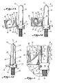
- the storage means 68 is shown with the lid 80 in the open position for providing access to the interior of the storage means.
- the box-like storage means is mounted on the mandrel 54 by means of a projectng lug or ear 69 (housing an aperature disposed therethrough) which is inserted in a slot 69' of the alignment head 58 (see Fig. 3C) and secured by means of a pin or shaft 70.
- the shaft 70 permits limited vertical arcuate movement in a vertical plane of the storage means 68 toward or away from the mold core 56 to position the gate section 72 as previously described.
- the storage means 68 and gate section 72 are shown in their "down” or “disengaged” position relative to the surface of mold core 56.
- a length ot flexible tubing 48 has been anchored at one end 47 in a shallow attachment port 74 at the extreme extending tip of the penile prosthesis mold core 56.
- a first portion of the tubing 48' has been positioned over the surface of the mold core 56 down to a predetermined location 45 fixed by the gate section 72 of storage means 68 that has been rotated to its "up” or “engaged” position relative to the surface of the mold core 56.
- the remaining length of tubing and free end 49 are inserted through the gate aperture 86 and threaded through channel 84 and aperture 85 into the storage cavity 82.
- the remaining length of tubing 48 and the free end 49 are coiled in the cavity 82 for storage.
- the gate section 72 of the box-like member 78 has outer surfaces 90, 92 and 94 that cooperate with the surfaces of mold core 56 and the surfaces of mold cavity 67 to form the outer surface of the prosthesis 20 and define the exit location 45 of the tubing 48 from the molded prosthesis.
- the surface 90 of the gate section has a shoulder contour that coincides with the contour of the annular shoulder 71 in the mold cavity 67.
- the curved longitudinal surface 94 that is closely spaced parallel to the surface of mold core 56, corresponds to the contour and shape of the mold cavity surface 79 intermediate annular shoulders 71 and 73, which correspondingly forms the thinner section 46 of the prosthesis (see Fig. 1).
- the slanted shoulder 92 of gate section 72 corresponds to the upper annular shoulder of the mold cavity annular channel 73.
- the gate section 72 has defined mold surfaces 90, 92 and 94 that cooperate with the mold core 56 and the female mold cavity surface 67 to form at least a portion of the outer surface of the molded prosthesis, and, particularly, to locate and define the surface contour of the molded prosthesis at the exit point for the tubing 48.
- the gate section 72 also provides an internal lip 88 that is adjacent the outer surface 90 and aperture 86 and partially covers or closes the width of channel 84. Lip 88 provides a means of "squeezing" the tubing 48 at the point it enters the gate aperture 86 to increase the sealing pressure at the surface 90 due to the internal resilience of the tubing 48.
- Lip 88 also "grips" the tubing at this point to prevent its "popping out” of aperture 86 while the remaining length and free end 49 of tubing 43 is coiled and stored in cavity 82.
- the tubing 48 is resilient and elastic, it can easily be defeormed, without damage, to be manually inserted into and withdrawn from aperture 86 and channel 84 under lip 88.
- lid 80 Reterring to Figs. 4 and 12, the relationship of the lid 80 to the body member 78 and, in particular, gate section 72 is shown.
- the inner surface 83 of lid 80 is machined to effect a tight sealing fit with surface 79 of body member 78, and to close channel 84.
- lid 80 has a relief groove 89 disposed therein which corresponds to the length of lip 88.
- the relief groove 89 is provided in lid 80 to accommodate any "protruding" or “bulging” of tubing 48 that may occur alongside of lip 88 when the tubing 48 is compressed and deformed to fit into aperature 86 and under lip 88.
- the relief groove 89 will accommodate any "bulging" of tubing 48 and prevent pinching of the tubing between lid 80 and body member 78 that could damage the tubing at that point.
- Fig. 6 discloses the relationships between injection molding female mold halves 62-62' and the male mold core 56 and mandrel 54 carrying the storage means 68 according to this invention. Referring to Figs. 2 and 6, a pair of injection molding female mold halves 62 and 62' are shown in a spaced relationship as would be typical of the separation of the mold halves just prior to or just subsequent to the actual injection molding process.
- the mold half 62 has an inner mold cavity surface 67 communicating with an injection sprue or port 64'. Mold half 62 also has a box-like cavity or recess 68' that cooperatively mates with the storage means 68 for inletting the storage means into the mold face 63 in order that the lid surface 80 of the storage means is flush with the outer mold face 63. Mold 62 has a pair of drilled apertures 96 for receiving the alignment pins 76 attached to the mandrel 54 and projecting from the rear of the enlarged alignment head 58. Mold half 62 has a mating cavity 58' for mating with the mandrel alignment head 58.
- the alignment head cavity 58' and the alignment pin apertures 96 are machined to an extremely close tolerance with the dimensions of the alignment head 58 and the guide pins 76 in order that the mandrel will precisely fit into mold half 62 and maintain the correct mold tolerances 66 (see Fig. 2) for each molded product.
- Mold half 62 also has an opening 60' in the lower face for accommodating the mandrel handle 60 and permitting its projection below the mold.
- the other female mold half 62' carries similar mating cavities, such as cavity surface 67 for cooperatively mating with the mold core 56 to form the mold cavity for the product, alignment head cavity 58' for receiving the alignment head 58, and the opening 60' by accommodating the mandrel handle 60. Mold half 62' also carries a mating injection port or sprue 64'.
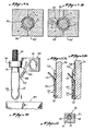
- Fig. 8 discloses another sealing embodiment to seal the gate section aperture 86 interface with the pre- formed product or tubing 48'.
- the resilient expansion pressure of the pre-formed member, such as an elastic, resilient and flexible tubing 48 will not consistently seal against the intrusion of the molding material into channel 84 through the interface of aperture 86 and tubing 48, because of higher injection pressures and thermal temperature expansion variations due to molding temperatures (see Fig. 7). A limited amount of leakage can sometimes occur but will generally form "flashing" that can easily be trimmed from the product.
- a simple solution is to use a flat disc 98 of a plastic or other compatible material that is inserted over the tubing portion 48' and against the gate section surface 90 to act as a seal between the tubing 48' and aperture 86.
- the sealing ring 98 will be self-energizing because of the pressure exerted by the injected material acting against the seal ring 98 to force it into engagement with tubing 48' and gate section surface 90 as shown by the arrows in Fig. 8.
- Figures 9A and 9B disclose another embodiment of the injection molding process and appratus according to this invention.
- Fig. 9A two female mold halves 100-100 are shown in cross section in cooperative mating relationship with a mold core 56.
- the mold half 100 has a vertical rib 102 that projects into the product mold cavity 66 between the female mold halves 100-100' and the mold core 56.
- the prosthesis 20 is injection molded to obtain the full thickness of body wall 34, but it will have a longitudinal channel 104 (see Fig. 9B) disposed therein as formed by rib 102.
- the female mold half 100 is removed and a tubing 48' is disposed in the longitudinal channel 104 and positioned with relation to the prosthesis as earlier described for the previous embodiment.
- the excess tubing 48 would then be stored in storage means 68, identical to that as hereinabove described, and a different female mold half 101, minus the longitudinal projecting rib 102, will be used as shown in Fig. 9B.
- the prosthesis is again injection molded as shown in Fig. 9B and the tubing 48' will be imbedded in the prosthesis wall 34 in the groove or channel 104. Then, when the mold halves 100'101' are opened and the mold core 56 with molded prosthesis 20 is removed, the excess tubing 48 can be freed from the storage means 68 in the identical manner as hereinabove discussed.
- Fig. 10 discloses a dip-molding apparatus to mold the prosthesis 20.
- the mold core 56, head 58 and handle 60 are identical to the mandrel 54 hereinabove described.
- the storage means 168 has been modified to provide a narrow extending neck 183 connecting the gate section 172 to the box-like storage means 168.
- the function and general construction of the storage means 168 is identical to that of the storage means 68 hereinabove described, except for the extended neck portion 183 connecting with gate section 172.
- Gate section 172 is also identical in general function and construction to gate section 72 hereinabove described.
- tubing portion 48' is anchored and positioned on mold core 56 in a manner identical to that previously described for the injection molding embodiment, and the remaining length 48 is inserted through neck 183 and coiled for storage in the cavity in storage means 168. Then the mold core 56 will be dipped sucessively in a source of liquid plastic material 109 to apply successive coats 108 of the material on the mold core 56 until the desired thickness is achieved. The plastic material will also coat a portion of the neck 183 and gate section 172, but that material may be easily trimmed from the prosthesis at the gate 172 interface at 45 with the prosthesis body (see Fig. 1).
- Figs. 11A and 11B show a prosthesis 120 that is formed in a combination of injection molding and dip molding steps.
- a prosthesis 120 is shown partially completed after having been injection molded to imbed tubing 48' in wall portion 134. However, the prosthesis terminates in an open end having a shoulder 136.
- the injection molded prosthesis of Fig. 11A is then dip-molded in accordanace with the process and apparatus of Fig. 10, to provide an overall thin layer 134' of molded material bonded to but overlying the injection molded body 134.
- a thin, sleeve-like portion 138 will be formed that corresponds to the thin, sleeve-like portion 38 as shown in Fig. 1, while the resulting shoulder 136' corresponds to the annular ridge or shoulder 36 as shown in Fig. 1.
- the storage means, 68 and 168 as hereinbefore described, can be utilized in protecting the excess tubing 48 during each of the injection molding and the dip molding steps in accordance with this invention.
Landscapes
- Engineering & Computer Science (AREA)
- Health & Medical Sciences (AREA)
- Mechanical Engineering (AREA)
- Heart & Thoracic Surgery (AREA)
- Life Sciences & Earth Sciences (AREA)
- Chemical & Material Sciences (AREA)
- Reproductive Health (AREA)
- Biomedical Technology (AREA)
- Manufacturing & Machinery (AREA)
- Vascular Medicine (AREA)
- Composite Materials (AREA)
- Animal Behavior & Ethology (AREA)
- General Health & Medical Sciences (AREA)
- Public Health (AREA)
- Veterinary Medicine (AREA)
- Moulds For Moulding Plastics Or The Like (AREA)
- Injection Moulding Of Plastics Or The Like (AREA)
- Orthopedics, Nursing, And Contraception (AREA)
Applications Claiming Priority (2)
| Application Number | Priority Date | Filing Date | Title |
|---|---|---|---|
| US654782 | 1984-09-26 | ||
| US06/654,782 US4623116A (en) | 1984-09-26 | 1984-09-26 | Apparatus for protecting a pre-formed projecting appendage during plastic molding |
Publications (2)
| Publication Number | Publication Date |
|---|---|
| EP0177254A2 true EP0177254A2 (de) | 1986-04-09 |
| EP0177254A3 EP0177254A3 (de) | 1988-01-20 |
Family
ID=24626221
Family Applications (1)
| Application Number | Title | Priority Date | Filing Date |
|---|---|---|---|
| EP85306807A Withdrawn EP0177254A3 (de) | 1984-09-26 | 1985-09-25 | Verfahren und Vorrichtung zum Schützen eines vorgeformten, vorragenden Anhängsels während des Kunststoffgiessens |
Country Status (4)
| Country | Link |
|---|---|
| US (1) | US4623116A (de) |
| EP (1) | EP0177254A3 (de) |
| JP (1) | JPS61160215A (de) |
| CA (1) | CA1254360A (de) |
Cited By (1)
| Publication number | Priority date | Publication date | Assignee | Title |
|---|---|---|---|---|
| US5554141A (en) * | 1990-05-15 | 1996-09-10 | Colplast A/S | Thermoplastic uridom and method and apparatus for the manufacturing thereof |
Families Citing this family (3)
| Publication number | Priority date | Publication date | Assignee | Title |
|---|---|---|---|---|
| DE10359975A1 (de) * | 2003-12-18 | 2005-07-14 | Priamus System Technologies Ag | Verfahren zum Betreiben einer Arbeitsgerätschaft |
| EP2536361B1 (de) * | 2010-02-19 | 2015-07-29 | Inspire AG IRPD | Verfahren und vorrichtung zur herstellung eines patientenspezifischen implantats |
| CN110279510B (zh) * | 2015-07-05 | 2021-11-16 | 大庆元子科技开发有限公司 | 一种安全套 |
Family Cites Families (20)
| Publication number | Priority date | Publication date | Assignee | Title |
|---|---|---|---|---|
| US2330399A (en) * | 1937-09-11 | 1943-09-28 | American Anode Inc | Distensible bag catheter |
| US2443630A (en) * | 1943-08-10 | 1948-06-22 | Purdue Research Foundation | Fluorination of carbon tetrachloride |
| DE1073193B (de) * | 1954-07-24 | 1960-01-14 | Bünder Glas G. m. b. H., Bünde (Westf.) | Spritzgussform zur herstellung von injektionsspritzen aus thermoplastischem kunststoff mit eingesetzter metallener injektionsnadel |
| FR1200745A (fr) * | 1956-10-04 | 1959-12-23 | Outil de forage de petite dimension et procédé de fabrication de cet outil | |
| GB866287A (en) * | 1957-02-27 | 1961-04-26 | Rempel Mfg Inc | Improvements in toys |
| US3287483A (en) * | 1963-03-28 | 1966-11-22 | Madeline F Mcgill | Method of producing snelled fish hooks |
| US3328846A (en) * | 1963-05-14 | 1967-07-04 | Madeline F Mcgill | Die structure for producing weedless fish hooks |
| US3484516A (en) * | 1967-04-06 | 1969-12-16 | Sta Rite Industries | Method of molding a transparent teat cup shell |
| US3898121A (en) * | 1970-11-23 | 1975-08-05 | Dunlop Ltd | Apparatus for molding hollow rubber articles |
| US3761557A (en) * | 1971-05-06 | 1973-09-25 | A Werner | A method of reinforcing pipe coatings |
| US3901965A (en) * | 1972-02-14 | 1975-08-26 | Iii Henry W Honeyman | Method of making an inflatable catheter |
| US3919374A (en) * | 1973-04-23 | 1975-11-11 | Automatic Liquid Packaging | Method for blow molding a container having an auxiliary component formed as an integral part of it |
| US4210478A (en) * | 1973-05-08 | 1980-07-01 | International Paper Company | Method of making a catheter |
| US3991146A (en) * | 1974-04-01 | 1976-11-09 | Imperial Chemical Industries Limited | Method of encapsulating an insert in plastics material by injection molding |
| US3887323A (en) * | 1974-06-24 | 1975-06-03 | Baxter Laboratories Inc | Die assembly for heat-sealing tubing ends to sheeting in transverse relationship |
| US3959429A (en) * | 1975-02-03 | 1976-05-25 | International Paper Company | Method of making a retention catheter and molding a tip thereon |
| US4175554A (en) * | 1978-03-16 | 1979-11-27 | Gerow Frank J | Prosthesis of male impotence |
| US4284459A (en) * | 1978-07-03 | 1981-08-18 | The Kendall Company | Method for making a molded catheter |
| AU2088683A (en) * | 1982-11-18 | 1984-05-24 | Abbott Laboratories | Catheter assembly |
| DE3314108A1 (de) * | 1983-04-19 | 1984-10-25 | C.F. Spiess & Sohn Kunststoffwerk GmbH & Co, 6719 Kleinkarlbach | Verfahren und vorrichtung zum herstellen von hohlkoerpern mit zumindest bereichsweise zwei- oder mehrschichtiger wand |
-
1984
- 1984-09-26 US US06/654,782 patent/US4623116A/en not_active Expired - Fee Related
-
1985
- 1985-09-25 CA CA000491542A patent/CA1254360A/en not_active Expired
- 1985-09-25 EP EP85306807A patent/EP0177254A3/de not_active Withdrawn
- 1985-09-26 JP JP60213593A patent/JPS61160215A/ja active Pending
Cited By (1)
| Publication number | Priority date | Publication date | Assignee | Title |
|---|---|---|---|---|
| US5554141A (en) * | 1990-05-15 | 1996-09-10 | Colplast A/S | Thermoplastic uridom and method and apparatus for the manufacturing thereof |
Also Published As
| Publication number | Publication date |
|---|---|
| JPS61160215A (ja) | 1986-07-19 |
| CA1254360A (en) | 1989-05-23 |
| EP0177254A3 (de) | 1988-01-20 |
| US4623116A (en) | 1986-11-18 |
Similar Documents
| Publication | Publication Date | Title |
|---|---|---|
| US4695241A (en) | Dip mold and process | |
| US4097992A (en) | Method for producing artificial dentures | |
| US4734241A (en) | Method for protecting a pre-formed projecting appendage during plastic molding | |
| CA1258562A (en) | Process and apparatus for the production of an injection molded part | |
| JPS63154314A (ja) | 射出成形方法及びこの方法によるプラスティック部品 | |
| US4623116A (en) | Apparatus for protecting a pre-formed projecting appendage during plastic molding | |
| EP0896871A3 (de) | Ventilanschnittsystem und Formverfahren | |
| US2977636A (en) | Method of molding a hollow rubber article | |
| ES8402757A1 (es) | "procedimiento para la fabricacion de un tubo de material sintetico". | |
| ES440440A1 (es) | Un metodo de fabricar una cabeza de muneca perfeccionada. | |
| US4186924A (en) | Arthritic golf club grip | |
| CN105829054A (zh) | 用于制作多部件中空制品的方法和设备以及由此制作的制品 | |
| EP0273769A2 (de) | Verfahren und Vorrichtung zum Giessen | |
| EP0503612A1 (de) | Elastische Form und Verfahren zur Herstellung von Formteilen mit dieser Form | |
| EP3619021B1 (de) | Form zum spritzgiessen einer verschlussanordnung | |
| JPH0346519A (ja) | オイルレベルゲージの製造方法 | |
| CA1114572A (en) | Mold for encapsulating a component having non-axial leads | |
| JPS5591642A (en) | Holding device for inserted body at enclosing molder | |
| JP3727129B2 (ja) | 埋込物を有する樹脂成型品の製造方法 | |
| EP3718508B1 (de) | Form und formverfahren für körperimplantate, insbesondere für brustimplantate | |
| JPH0245971B2 (ja) | Goseijushitsutsujotainoseikeihoho | |
| JPH069827Y2 (ja) | 人形の腕部及び指先部の射出成形金型 | |
| JP2000067675A (ja) | ポリマー碍子の外被成形方法 | |
| JP3125468B2 (ja) | 射出成形金型 | |
| WO1998056558A8 (de) | Verfahren und vorrichtung zum spritzgiessen eines kunststoffkörpers mit innengewinde |
Legal Events
| Date | Code | Title | Description |
|---|---|---|---|
| PUAI | Public reference made under article 153(3) epc to a published international application that has entered the european phase |
Free format text: ORIGINAL CODE: 0009012 |
|
| AK | Designated contracting states |
Kind code of ref document: A2 Designated state(s): AT BE CH DE FR GB IT LI LU NL SE |
|
| PUAL | Search report despatched |
Free format text: ORIGINAL CODE: 0009013 |
|
| AK | Designated contracting states |
Kind code of ref document: A3 Designated state(s): AT BE CH DE FR GB IT LI LU NL SE |
|
| 17P | Request for examination filed |
Effective date: 19880718 |
|
| 17Q | First examination report despatched |
Effective date: 19890428 |
|
| STAA | Information on the status of an ep patent application or granted ep patent |
Free format text: STATUS: THE APPLICATION IS DEEMED TO BE WITHDRAWN |
|
| 18D | Application deemed to be withdrawn |
Effective date: 19910403 |