EP0177275A2 - Als Bildaufnahmevorrichtung verwendbarer Photosensor - Google Patents
Als Bildaufnahmevorrichtung verwendbarer Photosensor Download PDFInfo
- Publication number
- EP0177275A2 EP0177275A2 EP85306847A EP85306847A EP0177275A2 EP 0177275 A2 EP0177275 A2 EP 0177275A2 EP 85306847 A EP85306847 A EP 85306847A EP 85306847 A EP85306847 A EP 85306847A EP 0177275 A2 EP0177275 A2 EP 0177275A2
- Authority
- EP
- European Patent Office
- Prior art keywords
- thin film
- photodiode
- film transistor
- electrode
- inter
- Prior art date
- Legal status (The legal status is an assumption and is not a legal conclusion. Google has not performed a legal analysis and makes no representation as to the accuracy of the status listed.)
- Granted
Links
Images



Classifications
-
- H—ELECTRICITY
- H10—SEMICONDUCTOR DEVICES; ELECTRIC SOLID-STATE DEVICES NOT OTHERWISE PROVIDED FOR
- H10F—INORGANIC SEMICONDUCTOR DEVICES SENSITIVE TO INFRARED RADIATION, LIGHT, ELECTROMAGNETIC RADIATION OF SHORTER WAVELENGTH OR CORPUSCULAR RADIATION
- H10F39/00—Integrated devices, or assemblies of multiple devices, comprising at least one element covered by group H10F30/00, e.g. radiation detectors comprising photodiode arrays
- H10F39/10—Integrated devices
- H10F39/12—Image sensors
- H10F39/18—Complementary metal-oxide-semiconductor [CMOS] image sensors; Photodiode array image sensors
-
- H—ELECTRICITY
- H10—SEMICONDUCTOR DEVICES; ELECTRIC SOLID-STATE DEVICES NOT OTHERWISE PROVIDED FOR
- H10F—INORGANIC SEMICONDUCTOR DEVICES SENSITIVE TO INFRARED RADIATION, LIGHT, ELECTROMAGNETIC RADIATION OF SHORTER WAVELENGTH OR CORPUSCULAR RADIATION
- H10F30/00—Individual radiation-sensitive semiconductor devices in which radiation controls the flow of current through the devices, e.g. photodetectors
- H10F30/20—Individual radiation-sensitive semiconductor devices in which radiation controls the flow of current through the devices, e.g. photodetectors the devices having potential barriers, e.g. phototransistors
- H10F30/21—Individual radiation-sensitive semiconductor devices in which radiation controls the flow of current through the devices, e.g. photodetectors the devices having potential barriers, e.g. phototransistors the devices being sensitive to infrared, visible or ultraviolet radiation
- H10F30/22—Individual radiation-sensitive semiconductor devices in which radiation controls the flow of current through the devices, e.g. photodetectors the devices having potential barriers, e.g. phototransistors the devices being sensitive to infrared, visible or ultraviolet radiation the devices having only one potential barrier, e.g. photodiodes
- H10F30/227—Individual radiation-sensitive semiconductor devices in which radiation controls the flow of current through the devices, e.g. photodetectors the devices having potential barriers, e.g. phototransistors the devices being sensitive to infrared, visible or ultraviolet radiation the devices having only one potential barrier, e.g. photodiodes the potential barrier being a Schottky barrier
-
- H—ELECTRICITY
- H10—SEMICONDUCTOR DEVICES; ELECTRIC SOLID-STATE DEVICES NOT OTHERWISE PROVIDED FOR
- H10F—INORGANIC SEMICONDUCTOR DEVICES SENSITIVE TO INFRARED RADIATION, LIGHT, ELECTROMAGNETIC RADIATION OF SHORTER WAVELENGTH OR CORPUSCULAR RADIATION
- H10F39/00—Integrated devices, or assemblies of multiple devices, comprising at least one element covered by group H10F30/00, e.g. radiation detectors comprising photodiode arrays
- H10F39/80—Constructional details of image sensors
-
- H—ELECTRICITY
- H10—SEMICONDUCTOR DEVICES; ELECTRIC SOLID-STATE DEVICES NOT OTHERWISE PROVIDED FOR
- H10K—ORGANIC ELECTRIC SOLID-STATE DEVICES
- H10K30/00—Organic devices sensitive to infrared radiation, light, electromagnetic radiation of shorter wavelength or corpuscular radiation
- H10K30/80—Constructional details
- H10K30/81—Electrodes
Definitions
- the invention relates to a photosensor and, more particularly, to a photosensor suited for an image sensor.
- a photodiode using hydrogenated amorphous silicon (a-Si : H) film has attracting attention as an image sensor element for use in such an apparatus as an electronic copier and a facsimile apparatus. Since the a-Si : H film has high photosensitivity and can be easily made large in area, it is particularly suited for a contact type image sensor.
- An image sensor is formed by arranging a great number of photodiodes in line.
- the photodiode usually takes a sandwich structure in which an a-Si : H film is sandwiched between upper and lower electrodes.
- the lower electrode is made of chromium (Cr) or like, while the upper electrode is made of transparent, electrically conductive film such as indium tin oxide (ITO) film.
- ITO indium tin oxide
- a Schottky barrier is formed at interface between the a-Si : H film and upper electrode, thus exhibiting a diode characteristic.
- the lower .electrode serves as a cathode electrode, and the upper electrode as an anode electrode.
- a large number of such photodiodes are formed in line on a substrate, thus constituting an image sensor.
- the anode of each photodiode is connected to the negative terminal of a DC power supply, and the cathode of the photodiode is connected through a charging switch to the positive terminal of the DC power supply.
- the cathode of the photodiode is connected through a charge readout switch to a common output amplifier.
- the signal voltage taken from the capacitor is proportional to the product of the light-receiving area, illumination intensity and storage time.
- the recent trend for higher operation speed and higher resolution calls for smaller light-receiving area and shorter storage time; for instance, a resolution of 16 bits/mm and a storage time of 1 msec. are required.
- the light-receiving area of one photodiode corresponding to the resolution of 16 bits/mm is 3.91 x 10 /mm .
- the inter-electrode capacitance is approximately 0.2 pF. Under the conditions of a practical illumination intensity of 500 lx and an internal quantum efficiency of 1, the maximum signal voltage is found to be approximately 6.8 V by calculation.
- the noise in the image sensor includes a switching noize component resulting from the switch element (i.e., transistor) and a dark current noise component based on dark current in the photodiode. While the switching noise is irrelevant to temperature, the dark current noise increases with temperature. At 40°C or below, the signal-to-noise ratio of the read-out signal is 38 dB at the most, which is insufficient in practice. Recently, a signal-to-noise ratio of 80 dB or above in a temperature range of 0 to 80°C is required in addition to the high operation speed and high resolution.
- a combination of a solar battery and a M OS transistor is known, as is disclosed in Japanese Patent early Publication No. 59-25280 published on February 9, 1984.
- a solar battery using a-Si : H film is formed on a MOS transistor formed on a silicon substrate, connected between the gate and source of this transistor.
- the drain current of the MOS transistor is controlled by incident light on the solar battery.
- the substrate is made of silicon crystal, and cannot easily be made large. Therefore, the structure is not suited for a photosensor for use in an image sensor which requires a large area.
- An object of the invention is to provide an improved photosensor.
- Another object of the invention is to provide a photosensor which can realize a high signal-to-noise ratio.
- a further object of the invention is to provide an image sensor having a high resolution, a high operation speed and a high signal-to-noise ratio.
- a photosensor comprises a thin film transistor formed on a substrate and having a gate electrode, and drain and source electrodes forming a channel therebetween, in response to a control voltage applied to the gate electrode, through which a channel current controlled by the control voltage flows; an amorphous silicon photodiode formed on the substrate integral with the thin film transistor and between either the drain electrode or source electrode and the gate electrode of the thin film transistor, the amorphous silicon photodiode having an inter-electrode capacitance; charging means for charging the inter- electrode capacitance of the photodiode; and detecting means for detecting the channel current of the thin film transistor controlled by the voltage across the inter-electrode capacitance of the photodiode, which varies in response to incident light after the charging of the inter-electrode capacitance.
- the photodiode includes a cathode electrode, an anode electrode consisting of transparent conductive film, and hydrogenated amorphous silicon film sandwiched between the cathode and anode electrodes, the cathode and anode electrodes being electrically connected to the respective drain and gate electrodes of the thin film transistor.
- the cathode and anode electrodes may be electrically connected to the respective gate and source electrodes of the thin film transistor.
- the charging means includes a DC power supply, a charge switching element for coupling the DC power supply to the photodiode to charge the inter-electrode capacitance thereof.
- the charge switching element is formed of a thin film transistor, formed on the substrate adjacent to the thin film transistor and photodiode, which is turned on and off by an externally applied control signal.
- the detecting means includes a charge storage capacitor coupled to the thin film transistor and charged by the channel current thereof; an output amplifier for taking out an output signal of the photosensor; and a detection switching element for coupling the charge storage capacitor to the output amplifier, which is turned on and off by an externally applied control signal.
- the detecting switching element is formed of a thin film transistor, and the charge storage capacitor and detecting switching element are formed on the circuit substrate.
- Fig. 1 shows a photosensor of this invention, formed in a staggered configuration on a substrate.
- the substrate 1 is an insulating plate having a smooth (i.e., lustrous) surface. More specifically, it is an alkali metal-free glass plate having an optically polished major surface.
- a photodiode 2 of a sandwich structure and a thin film transistor (TFT) 3 are formed on the major surface of substrate 1, integrally and adjacent to each other.
- a charging transistor (TFT) 4 and a detection transistor (TFT) 5 are formed adjacent to T FT 3 on substrate 1.
- a capacitor 6 is formed between TFTs 4 and 5. More specifically, TFT 3 has drain and source electrodes 11 and 12 formed on the major surface of substrate 1. Between drain and source electrodes 11 and 12 are sequentially formed an active layer 13 which consists of a-Si : H film, an insulating layer 14 of SiNx, and a gate electrode layer 15 consisting of, for instance, chromium.
- Drain and source electrodes 11 and 12 may be formed by vacuum deposition of aluminum and by a subsequent photoetching process (PEP).
- a-Si : H film 13 and SiNx film 14 may be formed by plasma CVD process, from 100 % SiH 4 gas and SiH 4/ N 2 mixture gas, respectively.
- Gate insulating film 14 may be double-layer film made of a SiNx layer and a SiOx layer, with the SiNx layer provided on the side of active layer 13.
- Gate electrode 15 may be formed by PEP.
- Photodiode 2 has a cathode electrode 16, which is formed of the same material and by the same process as gate electrode 15, on a portion of drain electrode layer 11 that is not covered with insulating film 14 and on a portion of insulating film 14.
- a-Si : H film 17 is formed on a portion of cathode electrode 16 over insulating layer 14.
- An anode electrode 18 consisting of transparent conductive film is formed on a-Si : H film 17 and insulating layer 14 so as to partly contact gate electrode 15.
- photodiode 2 is formed which has a sandwich structure with the a-Si : H film sandwiched between the anode and cathode electrodes.
- gate electrode 15 and drain electrode 11 of TFT 3 are electrically connected to respective anode and cathode electrodes 18 and 16 of photodiode 2.
- ITO may be used for a material of the transparent conductive film.
- Light 20 is incident on a-Si : H film 17 through transparent anode electrode 18 of photodiode 2. Since the TFT and photodiode are formed adjacent to each other on the substrate, a wiring capacitance can be greatly reduced, improving the signal-to-noise ratio.
- Charging TFT 4, detection TFT 5 and capacitor 6 are formed integrally with photodiode 2 and TFT 3 on substrate 1.
- Capacitor 6 is formed of source electrode layer 12, insulating film 14 formed thereon, and electrode layer 21 formed on insulating film -14. Electrode 21 is spaced apart from gate electrode 15 of TFT 3, and a-Si : H film 22 is formed between electrode layer 21 and gate electrode 15.
- An insulating layer 23 is formed on electrode layer 21, a-Si : H film 22 and gate electrode 15 of TFT 3.
- a gate electrode 24 is formed on insulating film 23.
- charging TFT 4 for charging the interelectrode capacitance of photodiode 2 is formed.
- Gate electrode 15 of transistor 3 and electrode 21 of capacitor 6 are used as the drain and source electrodes of charging TFT 4, respectively.
- An electrode 24 is formed on the major surface of substrate 1, and an active layer 25, or a-Si : H layer, is formed between electrodes 12 and 24.
- Insulating layer 14 is formed to extend on electrodes 11 and 12 and active layers 13 and 25.
- a gate electrode 26 is formed over active layer 25 with insulating layer 14 interposed therebetween. In this way, detection TFT 5 is formed. Electrodes 12 and 24 are used as the drain and source electrodes of detection transistor 5, respectively.
- Fig. 2 i.e., a circuit diagram thereof.
- Charging TFT (switch) 4 and detection TFT (switch) 5 are normally off. They are turned on by a charging pulse and a readout pulse from a control circuit (not shown), respectively.
- a charging pulse turns charging TFT 4 on
- the inter-electrode capacitance C of photodiode 2 is charged by power supply 27.
- TFT 3 is off since its gate electrode 15 is coupled to electrode 21 placed at ground potential through the channel of conducting TFT 4.
- the drain current of transistor 3 is a small off-current I D off.
- the inter-electrode capacitance C of photodiode 2 gradually discharges in accordance with photocurrent corresponding to the incident image information light 20.
- the discharging of inter-electrode capacitance C raises the potential on gate electrode 15 of TFT 3.
- a drain current based on the gate potential flows in TFT 3.
- Capacitor 6 is charged by this drain current. The extent of charging capacitor 6 depends on the intensity of light 20 incident on photodiode 2.
- detection TFT 5 When the read-out pulse is applied to the gate electrode of detection TFT 5, detection TFT 5 is turned on. As a result, the voltage across capacitor 6 is applied to output amplifier 28, so that an output image information signal is obtained.
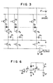
- Fig. 3 shows a circuit diagram of an image sensor in which a plurality of photosensors as described above are arranged in a line. More specifically, in this image sensor, n photosensors, each of which corresponds to one picture element (i.e., one dot) and is constituted by a photodiode 2, a TFT 3, a charging TFT 4, a detection TFT 5 and a capacitor 6, are arranged in line on a substrate. Each photosensor is wired in the manner as shown in Fig. 2. The n photosensors are successively enabled by control signals having charging pulses and read-out pulses. Thus, the image information signal is taken from an output amplifier 28. Where the resolution is 16 dots/mm, n is approximately 3,500.
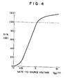
- Fig. 4 shows a relation between the signal-to-noise ratio of drain current I D of TFT 3 and gate-source voltage VGS thereof.
- the threshold voltage of TFT 3 is 2 to 3 V
- the signal-to-noise ratio is not less than 100 dB with respect to the drain current when the V GS changes by several volts.
- the signal voltage taken out from the photodiode having the sandwich structure i.e., voltage across the inter- electrode capacitor
- an output signal having a dynamic range of approximately 100 dB can be obtained by controlling the TF T gate voltage with the signal voltage from the photodiode and by detecting the drain current.
- the noise voltage such as switching noize and dark current noise
- the threshold voltage of TFT is on the order of the threshold voltage of TFT. This indicates that the noise voltage tends to be compressed, to further improve the signal-to-noise ratio.
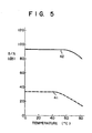
- Fig. 5 shows the temperature-dependency 41 of an output signal of a sandwich type photodiode consisting of a TFT and a photodiode, and also the temperature-dependency 42 of an output signal of the photosensor according to the invention.
- a signal-to-noise ratio of 80 dB or above can be realized in a temperature range of 0 to 80°C. This can meet the requirements of a high performance image sensor, i.e., the resolution of 16 dots/mm and the readout speed of 1 msec.
- the substrate 1 may be made of glazed ceramic or organic film of a polyimide resin which can withstand a high temperature of 400°C.
- the active layer may be made of a-Si : H film or polycrystalline silicon film formed by a vacuum deposition process or spattering process.
- the photodiode may have a pin structure or any other structure.
- photodiode 2 may be connected between the gate electrode and source electrode of TFT 3 as shown in F ig. 6. It suffices to connect the photodiode between the drain or source electrode a channel, and the gate electrode. (A channel is formed between the drain and source electrodes.)
- the structure of the photodiode and TF T is not limited to the staggered structure shown in Fig. 1. Further, the positional relationship among drain and source electrodes 11 and 12, active layer 13, insulating layer 14 and gate electrode 15 of the TFT in the direction normal to the major surface of the substrate in Fig. 1 may be reversed as shown in Fig. 7. That is, an inverse staggered structure may be adopted. Further, the TFT may take a coplanar structure in which electrodes 11, 12 and 15 are formed on the same side of active layer 13 as shown in Fig. 8.
- the TFT may have the structures shown in Figs. 9 and 10.
- parts like those shown in Fig. 1 are designated by the same numerals.
- Fig. 9 shows a U MOS or V MOS transistor structure, in which an active layer 13 is sandwiched between drain and source electrodes 11 and 12, and an insulating layer 14 has a U- or V-shape extending from the drain electrode to the source electrode.
- Fig. 10 shows a SIT (static induction transistor) structure, in which an active layer 10 is sandwiched between drain and source electrodes 11 and 12, and a plurality of gate sections are provided.
- SIT static induction transistor
- the above embodiment is designed such that capacitor 6 is charged by the drain current of the TFT and subsequently the image information signal is read out through switch 5. However, it may be arranged to convert the drain current of the TFT directly into a voltage signal.
Landscapes
- Physics & Mathematics (AREA)
- Electromagnetism (AREA)
- Solid State Image Pick-Up Elements (AREA)
- Light Receiving Elements (AREA)
- Thin Film Transistor (AREA)
Applications Claiming Priority (2)
| Application Number | Priority Date | Filing Date | Title |
|---|---|---|---|
| JP204806/84 | 1984-09-29 | ||
| JP59204806A JPS6182466A (ja) | 1984-09-29 | 1984-09-29 | 光センサ |
Publications (3)
| Publication Number | Publication Date |
|---|---|
| EP0177275A2 true EP0177275A2 (de) | 1986-04-09 |
| EP0177275A3 EP0177275A3 (en) | 1988-09-07 |
| EP0177275B1 EP0177275B1 (de) | 1990-06-13 |
Family
ID=16496670
Family Applications (1)
| Application Number | Title | Priority Date | Filing Date |
|---|---|---|---|
| EP85306847A Expired - Lifetime EP0177275B1 (de) | 1984-09-29 | 1985-09-26 | Als Bildaufnahmevorrichtung verwendbarer Photosensor |
Country Status (5)
| Country | Link |
|---|---|
| US (1) | US4823178A (de) |
| EP (1) | EP0177275B1 (de) |
| JP (1) | JPS6182466A (de) |
| KR (1) | KR900006952B1 (de) |
| DE (1) | DE3578269D1 (de) |
Cited By (4)
| Publication number | Priority date | Publication date | Assignee | Title |
|---|---|---|---|---|
| US5408113A (en) * | 1992-06-30 | 1995-04-18 | Ricoh Company, Ltd. | High sensitivity improved photoelectric imaging device with a high signal to noise ratio |
| FR3026893A1 (fr) * | 2014-10-07 | 2016-04-08 | Alain Coty | Transistor a effet photovoltaique et moteur photovoltaique a puissance augmentee associe |
| CN107610604A (zh) * | 2017-09-25 | 2018-01-19 | 上海九山电子科技有限公司 | 一种led芯片、阵列基板、显示面板和显示装置 |
| US11428787B2 (en) | 2016-10-25 | 2022-08-30 | Trinamix Gmbh | Detector for an optical detection of at least one object |
Families Citing this family (35)
| Publication number | Priority date | Publication date | Assignee | Title |
|---|---|---|---|---|
| JP2569053B2 (ja) * | 1987-06-26 | 1997-01-08 | キヤノン株式会社 | イメ−ジセンサ |
| US4889983A (en) * | 1987-11-24 | 1989-12-26 | Mitsubishi Denki Kabushiki Kaisha | Image sensor and production method thereof |
| EP0490997A4 (en) * | 1989-09-06 | 1993-01-27 | The University Of Michigan, Intellectual Property Office | Multi-element-amorphous-silicon-detector-array for real-time imaging and dosimetry of megavoltage photons and diagnostic x-rays |
| JPH0734467B2 (ja) * | 1989-11-16 | 1995-04-12 | 富士ゼロックス株式会社 | イメージセンサ製造方法 |
| US6008078A (en) * | 1990-07-24 | 1999-12-28 | Semiconductor Energy Laboratory Co., Ltd. | Method for manufacturing a semiconductor device |
| AU1995092A (en) * | 1991-05-10 | 1992-12-30 | Q-Dot. Inc. | High-speed peristaltic ccd imager with gaas fet output |
| KR100382817B1 (ko) * | 1999-01-20 | 2003-05-09 | 엘지.필립스 엘시디 주식회사 | 생체감지패턴 및 이를 이용한 박막트랜지스터형 광센서 |
| US7009663B2 (en) * | 2003-12-17 | 2006-03-07 | Planar Systems, Inc. | Integrated optical light sensitive active matrix liquid crystal display |
| US7023503B2 (en) * | 2002-02-20 | 2006-04-04 | Planar Systems, Inc. | Image sensor with photosensitive thin film transistors |
| US7053967B2 (en) * | 2002-05-23 | 2006-05-30 | Planar Systems, Inc. | Light sensitive display |
| US7408598B2 (en) * | 2002-02-20 | 2008-08-05 | Planar Systems, Inc. | Light sensitive display with selected interval of light sensitive elements |
| JP2003332560A (ja) * | 2002-05-13 | 2003-11-21 | Semiconductor Energy Lab Co Ltd | 半導体装置及びマイクロプロセッサ |
| JP4373063B2 (ja) | 2002-09-02 | 2009-11-25 | 株式会社半導体エネルギー研究所 | 電子回路装置 |
| JP4094386B2 (ja) * | 2002-09-02 | 2008-06-04 | 株式会社半導体エネルギー研究所 | 電子回路装置 |
| JP4574118B2 (ja) * | 2003-02-12 | 2010-11-04 | 株式会社半導体エネルギー研究所 | 半導体装置及びその作製方法 |
| US20080084374A1 (en) * | 2003-02-20 | 2008-04-10 | Planar Systems, Inc. | Light sensitive display |
| US20080048995A1 (en) * | 2003-02-20 | 2008-02-28 | Planar Systems, Inc. | Light sensitive display |
| US7773139B2 (en) * | 2004-04-16 | 2010-08-10 | Apple Inc. | Image sensor with photosensitive thin film transistors |
| US20070109239A1 (en) * | 2005-11-14 | 2007-05-17 | Den Boer Willem | Integrated light sensitive liquid crystal display |
| JP5131508B2 (ja) * | 2005-11-14 | 2013-01-30 | Nltテクノロジー株式会社 | 受光回路 |
| US7688947B2 (en) * | 2006-10-17 | 2010-03-30 | Varian Medical Systems, Inc. | Method for reducing sensitivity modulation and lag in electronic imagers |
| KR101441429B1 (ko) * | 2007-09-21 | 2014-09-18 | 삼성디스플레이 주식회사 | 센서 박막 트랜지스터 및 이를 포함하는 박막 트랜지스터기판, 박막 트랜지스터 기판의 제조 방법 |
| US9310923B2 (en) | 2010-12-03 | 2016-04-12 | Apple Inc. | Input device for touch sensitive devices |
| US8638320B2 (en) | 2011-06-22 | 2014-01-28 | Apple Inc. | Stylus orientation detection |
| US8928635B2 (en) | 2011-06-22 | 2015-01-06 | Apple Inc. | Active stylus |
| US9329703B2 (en) | 2011-06-22 | 2016-05-03 | Apple Inc. | Intelligent stylus |
| US8889461B2 (en) | 2012-05-29 | 2014-11-18 | Taiwan Semiconductor Manufacturing Company, Ltd. | CIS image sensors with epitaxy layers and methods for forming the same |
| US9652090B2 (en) | 2012-07-27 | 2017-05-16 | Apple Inc. | Device for digital communication through capacitive coupling |
| US9176604B2 (en) | 2012-07-27 | 2015-11-03 | Apple Inc. | Stylus device |
| US9557845B2 (en) | 2012-07-27 | 2017-01-31 | Apple Inc. | Input device for and method of communication with capacitive devices through frequency variation |
| US10048775B2 (en) | 2013-03-14 | 2018-08-14 | Apple Inc. | Stylus detection and demodulation |
| US10845901B2 (en) | 2013-07-31 | 2020-11-24 | Apple Inc. | Touch controller architecture |
| US10067618B2 (en) | 2014-12-04 | 2018-09-04 | Apple Inc. | Coarse scan and targeted active mode scan for touch |
| US10474277B2 (en) | 2016-05-31 | 2019-11-12 | Apple Inc. | Position-based stylus communication |
| US12153764B1 (en) | 2020-09-25 | 2024-11-26 | Apple Inc. | Stylus with receive architecture for position determination |
Family Cites Families (15)
| Publication number | Priority date | Publication date | Assignee | Title |
|---|---|---|---|---|
| JPS5739582B2 (de) * | 1974-09-13 | 1982-08-21 | ||
| JPS5850030B2 (ja) * | 1979-03-08 | 1983-11-08 | 日本放送協会 | 光電変換装置およびそれを用いた固体撮像板 |
| JPS55128884A (en) * | 1979-03-28 | 1980-10-06 | Hitachi Ltd | Semiconductor photodetector |
| JPS56135981A (en) * | 1980-03-28 | 1981-10-23 | Canon Inc | Photoelectric conversion element |
| DE3112907A1 (de) * | 1980-03-31 | 1982-01-07 | Canon K.K., Tokyo | "fotoelektrischer festkoerper-umsetzer" |
| JPS56138965A (en) * | 1980-03-31 | 1981-10-29 | Canon Inc | Photoelectric converter |
| JPS5746224A (en) * | 1980-09-03 | 1982-03-16 | Canon Inc | Lens system equipped with auxiliary lens |
| JPS57114292A (en) * | 1981-01-06 | 1982-07-16 | Fuji Xerox Co Ltd | Thin film image pickup element |
| US4471371A (en) * | 1981-01-06 | 1984-09-11 | Fuji Xerox Co., Ltd. | Thin film image pickup element |
| US4517733A (en) * | 1981-01-06 | 1985-05-21 | Fuji Xerox Co., Ltd. | Process for fabricating thin film image pick-up element |
| JPS5922360A (ja) * | 1982-07-28 | 1984-02-04 | Matsushita Electric Works Ltd | 光入力モス型トランジスタ |
| JPS5925280A (ja) * | 1982-07-31 | 1984-02-09 | Matsushita Electric Works Ltd | 光入力mosトランジスタ |
| US4651185A (en) * | 1983-08-15 | 1987-03-17 | Alphasil, Inc. | Method of manufacturing thin film transistors and transistors made thereby |
| JPS60103676A (ja) * | 1983-11-11 | 1985-06-07 | Seiko Instr & Electronics Ltd | 薄膜トランジスタアレイの製造方法 |
| US4598305A (en) * | 1984-06-18 | 1986-07-01 | Xerox Corporation | Depletion mode thin film semiconductor photodetectors |
-
1984
- 1984-09-29 JP JP59204806A patent/JPS6182466A/ja active Pending
-
1985
- 1985-09-24 KR KR1019850007015A patent/KR900006952B1/ko not_active Expired
- 1985-09-26 DE DE8585306847T patent/DE3578269D1/de not_active Expired - Lifetime
- 1985-09-26 US US06/780,598 patent/US4823178A/en not_active Expired - Lifetime
- 1985-09-26 EP EP85306847A patent/EP0177275B1/de not_active Expired - Lifetime
Cited By (5)
| Publication number | Priority date | Publication date | Assignee | Title |
|---|---|---|---|---|
| US5408113A (en) * | 1992-06-30 | 1995-04-18 | Ricoh Company, Ltd. | High sensitivity improved photoelectric imaging device with a high signal to noise ratio |
| FR3026893A1 (fr) * | 2014-10-07 | 2016-04-08 | Alain Coty | Transistor a effet photovoltaique et moteur photovoltaique a puissance augmentee associe |
| WO2016055369A1 (fr) * | 2014-10-07 | 2016-04-14 | Alain Coty | Transistor à effet photovoltaïque et moteur photovoltaïque à puissance augmentée associé |
| US11428787B2 (en) | 2016-10-25 | 2022-08-30 | Trinamix Gmbh | Detector for an optical detection of at least one object |
| CN107610604A (zh) * | 2017-09-25 | 2018-01-19 | 上海九山电子科技有限公司 | 一种led芯片、阵列基板、显示面板和显示装置 |
Also Published As
| Publication number | Publication date |
|---|---|
| KR900006952B1 (ko) | 1990-09-25 |
| US4823178A (en) | 1989-04-18 |
| JPS6182466A (ja) | 1986-04-26 |
| EP0177275B1 (de) | 1990-06-13 |
| KR860002741A (ko) | 1986-04-28 |
| EP0177275A3 (en) | 1988-09-07 |
| DE3578269D1 (de) | 1990-07-19 |
Similar Documents
| Publication | Publication Date | Title |
|---|---|---|
| US4823178A (en) | Photosensor suited for image sensor | |
| EP0855746B1 (de) | Bilddetektor | |
| US4271420A (en) | Solid-state image pickup device | |
| US6681992B2 (en) | Image reading apparatus | |
| US11288484B2 (en) | Display device for integrating a solar battery module with a function of recognizing fingerprints | |
| KR100439944B1 (ko) | 박막트랜지스터형광감지센서,센서박막트랜지스터와그제조방법 | |
| US5591963A (en) | Photoelectric conversion device with dual insulating layer | |
| CN102007607A (zh) | 光敏结构和包括这种结构的装置 | |
| US4549088A (en) | Original reading device | |
| US5004903A (en) | Contact type image sensor device with specific capacitance ratio | |
| EP0260824B1 (de) | Schaltkreis für ein photoempfindliches Pixel mit einem belichteten Blockierglied | |
| JPS62145866A (ja) | センサ装置、光導電型センサの駆動方法及び駆動装置 | |
| US4886977A (en) | Photoelectric converter provided with voltage dividing means | |
| US6005238A (en) | Hybrid sensor pixel architecture with linearization circuit | |
| US6031248A (en) | Hybrid sensor pixel architecture | |
| US6252215B1 (en) | Hybrid sensor pixel architecture with gate line and drive line synchronization | |
| KR20000050791A (ko) | 박막 트랜지스터형 광 감지소자 | |
| JP2875844B2 (ja) | 薄膜トランジスタ型光センサの駆動方法及び駆動装置 | |
| US12455660B2 (en) | Optical touch detection circuit and optical touch display panel | |
| JP2921821B2 (ja) | 光電変換装置 | |
| US6051827A (en) | Hybrid sensor pixel architecture with threshold response | |
| JPH06177417A (ja) | ホトトランジスタ及びラインイメージセンサ | |
| US20230369356A1 (en) | Light sensing panel, light sensing display panel, and method for operating light sensing panel | |
| US4412227A (en) | Thermal head | |
| JP2660046B2 (ja) | イメージセンサ |
Legal Events
| Date | Code | Title | Description |
|---|---|---|---|
| PUAI | Public reference made under article 153(3) epc to a published international application that has entered the european phase |
Free format text: ORIGINAL CODE: 0009012 |
|
| 17P | Request for examination filed |
Effective date: 19851010 |
|
| AK | Designated contracting states |
Kind code of ref document: A2 Designated state(s): DE FR GB |
|
| PUAL | Search report despatched |
Free format text: ORIGINAL CODE: 0009013 |
|
| AK | Designated contracting states |
Kind code of ref document: A3 Designated state(s): DE FR GB |
|
| 17Q | First examination report despatched |
Effective date: 19881222 |
|
| GRAA | (expected) grant |
Free format text: ORIGINAL CODE: 0009210 |
|
| AK | Designated contracting states |
Kind code of ref document: B1 Designated state(s): DE FR GB |
|
| REF | Corresponds to: |
Ref document number: 3578269 Country of ref document: DE Date of ref document: 19900719 |
|
| ET | Fr: translation filed | ||
| PLBE | No opposition filed within time limit |
Free format text: ORIGINAL CODE: 0009261 |
|
| STAA | Information on the status of an ep patent application or granted ep patent |
Free format text: STATUS: NO OPPOSITION FILED WITHIN TIME LIMIT |
|
| 26N | No opposition filed | ||
| REG | Reference to a national code |
Ref country code: GB Ref legal event code: 746 Effective date: 19980915 |
|
| REG | Reference to a national code |
Ref country code: FR Ref legal event code: D6 |
|
| PGFP | Annual fee paid to national office [announced via postgrant information from national office to epo] |
Ref country code: FR Payment date: 20000912 Year of fee payment: 16 |
|
| PGFP | Annual fee paid to national office [announced via postgrant information from national office to epo] |
Ref country code: DE Payment date: 20000918 Year of fee payment: 16 |
|
| PGFP | Annual fee paid to national office [announced via postgrant information from national office to epo] |
Ref country code: GB Payment date: 20000920 Year of fee payment: 16 |
|
| PG25 | Lapsed in a contracting state [announced via postgrant information from national office to epo] |
Ref country code: GB Free format text: LAPSE BECAUSE OF NON-PAYMENT OF DUE FEES Effective date: 20010926 |
|
| REG | Reference to a national code |
Ref country code: GB Ref legal event code: IF02 |
|
| PG25 | Lapsed in a contracting state [announced via postgrant information from national office to epo] |
Ref country code: DE Free format text: LAPSE BECAUSE OF NON-PAYMENT OF DUE FEES Effective date: 20020501 |
|
| GBPC | Gb: european patent ceased through non-payment of renewal fee |
Effective date: 20010926 |
|
| PG25 | Lapsed in a contracting state [announced via postgrant information from national office to epo] |
Ref country code: FR Free format text: LAPSE BECAUSE OF NON-PAYMENT OF DUE FEES Effective date: 20020531 |
|
| REG | Reference to a national code |
Ref country code: FR Ref legal event code: ST |