EP0177284A2 - Kraftmessvorrichtung - Google Patents
Kraftmessvorrichtung Download PDFInfo
- Publication number
- EP0177284A2 EP0177284A2 EP85306871A EP85306871A EP0177284A2 EP 0177284 A2 EP0177284 A2 EP 0177284A2 EP 85306871 A EP85306871 A EP 85306871A EP 85306871 A EP85306871 A EP 85306871A EP 0177284 A2 EP0177284 A2 EP 0177284A2
- Authority
- EP
- European Patent Office
- Prior art keywords
- force
- detecting
- detecting apparatus
- parallel plate
- set forth
- Prior art date
- Legal status (The legal status is an assumption and is not a legal conclusion. Google has not performed a legal analysis and makes no representation as to the accuracy of the status listed.)
- Granted
Links
Images







Classifications
-
- G—PHYSICS
- G01—MEASURING; TESTING
- G01L—MEASURING FORCE, STRESS, TORQUE, WORK, MECHANICAL POWER, MECHANICAL EFFICIENCY, OR FLUID PRESSURE
- G01L19/00—Details of, or accessories for, apparatus for measuring steady or quasi-steady pressure of a fluent medium insofar as such details or accessories are not special to particular types of pressure gauges
- G01L19/06—Means for preventing overload or deleterious influence of the measured medium on the measuring device or vice versa
-
- G—PHYSICS
- G01—MEASURING; TESTING
- G01L—MEASURING FORCE, STRESS, TORQUE, WORK, MECHANICAL POWER, MECHANICAL EFFICIENCY, OR FLUID PRESSURE
- G01L1/00—Measuring force or stress, in general
- G01L1/04—Measuring force or stress, in general by measuring elastic deformation of gauges, e.g. of springs
- G01L1/044—Measuring force or stress, in general by measuring elastic deformation of gauges, e.g. of springs of leaf springs
-
- G—PHYSICS
- G01—MEASURING; TESTING
- G01L—MEASURING FORCE, STRESS, TORQUE, WORK, MECHANICAL POWER, MECHANICAL EFFICIENCY, OR FLUID PRESSURE
- G01L1/00—Measuring force or stress, in general
- G01L1/04—Measuring force or stress, in general by measuring elastic deformation of gauges, e.g. of springs
-
- G—PHYSICS
- G01—MEASURING; TESTING
- G01L—MEASURING FORCE, STRESS, TORQUE, WORK, MECHANICAL POWER, MECHANICAL EFFICIENCY, OR FLUID PRESSURE
- G01L1/00—Measuring force or stress, in general
- G01L1/20—Measuring force or stress, in general by measuring variations in ohmic resistance of solid materials or of electrically-conductive fluids; by making use of electrokinetic cells, i.e. liquid-containing cells wherein an electrical potential is produced or varied upon the application of stress
- G01L1/22—Measuring force or stress, in general by measuring variations in ohmic resistance of solid materials or of electrically-conductive fluids; by making use of electrokinetic cells, i.e. liquid-containing cells wherein an electrical potential is produced or varied upon the application of stress using resistance strain gauges
- G01L1/2206—Special supports with preselected places to mount the resistance strain gauges; Mounting of supports
- G01L1/2243—Special supports with preselected places to mount the resistance strain gauges; Mounting of supports the supports being parallelogram-shaped
-
- G—PHYSICS
- G01—MEASURING; TESTING
- G01L—MEASURING FORCE, STRESS, TORQUE, WORK, MECHANICAL POWER, MECHANICAL EFFICIENCY, OR FLUID PRESSURE
- G01L5/00—Apparatus for, or methods of, measuring force, work, mechanical power, or torque, specially adapted for specific purposes
- G01L5/16—Apparatus for, or methods of, measuring force, work, mechanical power, or torque, specially adapted for specific purposes for measuring several components of force
- G01L5/161—Apparatus for, or methods of, measuring force, work, mechanical power, or torque, specially adapted for specific purposes for measuring several components of force using variations in ohmic resistance
- G01L5/1627—Apparatus for, or methods of, measuring force, work, mechanical power, or torque, specially adapted for specific purposes for measuring several components of force using variations in ohmic resistance of strain gauges
-
- G—PHYSICS
- G01—MEASURING; TESTING
- G01L—MEASURING FORCE, STRESS, TORQUE, WORK, MECHANICAL POWER, MECHANICAL EFFICIENCY, OR FLUID PRESSURE
- G01L5/00—Apparatus for, or methods of, measuring force, work, mechanical power, or torque, specially adapted for specific purposes
- G01L5/22—Apparatus for, or methods of, measuring force, work, mechanical power, or torque, specially adapted for specific purposes for measuring the force applied to control members, e.g. control members of vehicles, triggers
- G01L5/226—Apparatus for, or methods of, measuring force, work, mechanical power, or torque, specially adapted for specific purposes for measuring the force applied to control members, e.g. control members of vehicles, triggers to manipulators, e.g. the force due to gripping
Definitions
- the present invention relates to an apparatus for detecting an external force applied to, for example, a robot hand arranged on the top end of an arm of a robot.
- a compliance mechanism is arranged on a wrist between the robot and a hand, to absorb any error in the relative position between the robot and the object.
- a force-detecting apparatus (force sensor) .is disposed which detects the above-mentioned error of the relative position as a reaction force acting on the wrist and corrects the position by feedback of the detected reaction force to the robot, so that the reaction force becomes zero.
- control of the robot is changed from position control to force control.
- the force sensor arranged on the wrist is rigid; a compliance mechanism is not preferred for the force sensor.
- the output of one strain gauge for detecting force or torque since the output of one strain gauge for detecting force or torque includes a plurality of force components, the respective components of force vectors cannot be independently detected. Accordingly, a complicated matrix operation circuit must be constructed to obtain the force components in the respective directions and the torque-separated outputs based on the outputs of the respective strain gauges, and furthermore, complicated operation expressions must be introduced for analyzing and calculating the force components and torques of the respective directions based on the outputs of the respective strain gauges and thus a long time is required for the operation. Accordingly, if this force-detecting apparatus is used for driving and controlling the robot, the control circuit becomes complicated and the cost is increased. Furthermore, a long time is necessary for conversion and separation of the respective components of the external force and it is impossible to control the robot at a high speed immediately in correspondence to the external force.
- An embodiment of the present invention can remove the above-m-entioned. defect of the conventional technique and provide a force-detecting apparatus in which force components and torques of the directions X, Y and Z can be easily separated and detected.
- a force-detecting apparatus comprising an elastic member deformable symmetrically with respect to the center, a first displacement-detecting means for detecting the displacements of the elastic member at positions symmetric with respect to the center in the same direction, and a second displacement-detecting means for detecting the displacements of the elastic member at positions symmetric with respect to the center in the opposite directions.
- Figure 33 is a schematic diagram illustrating a robot provided with a conventional force-detecting apparatus.
- the robot shown in Fig. 33 is a three-axis robot of the orthogonal axis type.
- a base 1 of a robot proper has an X-axis driving source (motor) for driving a first arm 2 (described below) in the direction of arrow A (X-axis).
- the first arm 2 has a Z-axis driving source (motor) for driving a second arm 3 in the direction of arrow B (Z-axis) and is moved in the direction of the X-axis by the X-axis driving source of the base 1.
- the second arm 3 has a Y-axis driving source (motor) for driving the arm 3 in the direction of arrow C (Y-axis) with respect to the first arm 2 and is moved in the direction of the Y-axis.
- a force-detecting apparatus 5 is arranged on the top end of the second arm 3 to detect a force applied to a hand 4. Accordingly, the hand 4 is positioned with respect to the direction of the X axis by the left-right movement of the first arm 2 and with respect to the directions of the Y-axis and Z-axis by the back-and-forth movement and vertical movement of the second arm 3, and thus three-dimensional positioning is accomplished by the three operation axes.
- a part 7 has a hole 8 in which the article 6 is fitted, and a tapered surface 9 is formed in the hole 8.
- the force-detecting apparatus shown in Fig. 33 comprises a parallel plate spring 5a shifting in the direction X, a parallel plate spring 5b shifting in the direction Y, and a cruciform plate spring (not shown) arranged on the upper or lower end and shifting in the direction Z.
- Each plate spring has a strain gauge (not shown) attached at an appropriate position to detect the displacement in each direction.
- This force-detecting apparatus 5 is attached to the wrist portion of the robot to make the robot perform the operation of fitting the article 6 into the hole 8 of the part 7. If an error arises in the relative position between the article 6 and the hole 8, an external force is applied to the hand 4, the respective plate springs of the force-detecting apparatus 5 are deformed according to this external force, and the strain gauges detect the displacement quantities of the plate springs. The force components in the directions X, Y and Z and the torques are calculated based on these displacement quantities, and the respective arms are driven and controlled so that the external force applied to the hand is cancelled, whereby the hand is moved to the correct position.
- an angular rod 321 of the direction X is constructed by parallel plate springs 323 and 324 arranged in the direction X and an angular rod 322 of the direction Y is constructed by parallel plate springs 325 and 326 arranged in the direction Y.
- a cruciform plate spring assembly is constructed by both the angular rods 321 and 322. Each plate spring is deformable symmetrically with respect to the central point D.
- strain gauges 314g through 314j are attached to both the opposite side faces of the angular rod 322 as an elastic member, but in Fig. 3, strain gauges are attached to one side face.
- Fig. 1 strain gauges 314g through 314j are attached to both the opposite side faces of the angular rod 322 as an elastic member, but in Fig. 3, strain gauges are attached to one side face.
- the strain gauges 314g and 314h contract while the strain gauges 314i and 314j extend. Accordingly, the respective strain gauges detect the displacements of the elastic member at the positions symmetric with respect to the central point D in the opposite directions (extension and contraction). As shown in Fig. l-(b), if a torque acts around the central point D, the respective strain gauges detect the displacements in the same direction (extensions or contractions) [in Fig. 1-(b), the gauges detect extensions]. If a bridge circuit as shown in Fig.
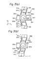
- strain gauge 2 is constructed by these strain gauges, only the force in the direction of the X-axis can be detected while reducing the output of the bridge circuit based on the deformations of the strain gauges by the torque to zero. Furthermore, where a similar force and torque act, if strain gauges are attached as shown in Fig. 3, the respective strain gauges detect the displacements in the same direction (contractions) when the force acts [Fig. 3-(a)] and the respective strain gauges detect the displacements in the opposite directions (extension and contraction) when the torque acts [Fig. 3-(b)]. If a bridge circuit as shown in Fig.
- reference numerals 323 through 326 represent parallel plate springs
- each of reference numerals 323a through 326b represents each plate (leaf) spring of the parallel plate springs
- reference numerals 314g, 314h, 314i, and 313j represent strain gauges which are attached at positions symmetric with respect to the central line passing through the center D of the hole 337.
- the strain gauges 314g and 314i and the strain gauges 314h and 314j are attached to the plate springs 326b and 325b located at positions symmetric with each other with respect to the central point D, respectively.
- the resistance value of each of the strain gauges 314g through 314j is R.
- strain gauges 314g through 314i are attached as shown in Fig. 1, and a bridge circuit as shown in Fig. 2 is constructed, only the force in the direction of the X-axis can be detected without any influence from the torque.
- Figure 3 is a diagram illustrating the method of detecting the torque around the axis without any influence of the force in the direction of the X-axis or Y-axis.
- the same members as those of Fig. 1 are represented by the same reference numerals as used in Fig. 1, and an explanation of these members is omitted.
- Figure 3 is different from Fig. 1 in that the strain gauges 314i and 314j are attached to the plate spring 325a. Namely, the strain gauges 314g through 314j are attached on the same face side so that the distances of the strain gauges 314g through 314j from the central point D are equal.
- the force around the axis that is, the torque
- the torque can be detected without any influence of the force in the direction of the direction of the X-axis.
- strain gauges are arranged so that their distances from the central point are equal because the same voltage value is given to each strain gauge under the same force. Namely, if the distances of the strain gauges from the central point are different, the displacement quantities of the plate springs become different, and therefore, the output voltages become different.
- the plate springs are arranged so that they shift in the direction of the Z-axis, it is possible to detect each of the forces in the directions X, Y, and Z.
- strain gauges are arranged in parallel for each of the parallel plate springs.
- each of 0 and 0' represents the central position, and e 1 is equal to e 2 . Since it is impossible to construct a plurality of bridge circuits by the same strain gauges, another pair of strain gauges 314 g and 314 h are independently attached.
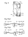
- a plate spring 401 is secured to a supporting member 402 connected to, for example, a robot arm (not shown) and a wrist portion 403 connected to a robot hand (not shown) is secured at the center portion of the plate spring 401.
- Strain gauges 414 g through 414 1 are attached at positions symmetric with respect to the center D of the plate spring 401.
- Figure 5-(a) shows the state where the force F is applied to the wrist 403 in the direction rectangular to the plate spring 401
- Fig. 5-(b) shows the state where a rotary moment (torque) M is applied to the plate spring 401.
- the strain gauges 414 g through 414 two bridge circuits shown in Figs. 6-(a) and 6-(b) are constructed.
- the bridge circuit shown in Fig. 6-(a) only the force F can be detected without any influence from the torque M
- the bridge circuit shown in Fig. 6-(b) only the torque M can be detected without any influence of the force F.
- two strain gauges 414 g and two strain gauges 414 h should be attached respectively as in the foregoing embodiment.
- the peripheral edge portion of the plate spring 401 may be connected to the hand side and the central portion of the plate spring 401 may be connected to the arm side.
- the central portion of the plate spring 401 is secured to an arm-connecting member 404 and the peripheral portion of the plate spring 401 is connected to a wrist 403 through a supporting member 405.
- Figure 8 and 9 illustrate an embodiment of the force-detecting apparatus according to the present invention, Fig. 8 being a perspective view and Fig. 9 being an exploded perspective view.
- reference numeral 30 represents a force-detecting module for detecting forces in the directions of the X-, Y- and Z-axes, and parallel plate springs al and all, bl and bl', and cl and cl' are constructed by forming angular holes a and a', b and b', and c and c' (by discharge processing or the like) on a cruciform structure comprising angular rods A and B extending in the directions X and Y.
- the parallel plate springs are arranged so that the displacement directions of the plate springs are orthogonal to each other. Accordingly, the force-detecting module 30 has degrees of freedom such that the deflection in the direction of the X-axis is borne by the parallel plate springs al and al', the deflection in the direction of the Y-axis is borne by the parallel plate springs bl and bl', and the deflection in the direction of the Z-axis is borne by the parallel plate springs cl and cl'.
- the force-detecting module 30 is supported by supporting members 31 and 32, and the supporting member 31 is connected to the angular rod B by screws 33 and the supporting member 32 is connected to the angular rod A by screws 34.
- the screws 33 and the screws 34 are shown in the drawings.
- An output rod 35 is connected to the supporting member 31 by a screw 36 so that the output rod 35 pierces through the hole 37 formed in the force-detecting module 30.
- the supporting member 32 is secured to a base stand of, for example, a robot. Screws (not shown) to be fitted in the screw holes 32a and 32b are used to fix the supporting member 32 to the robot.
- the output rod 35 is arranged so that the output rod 35 pierces through the hole 37 formed in the force-detecting module 30, the output rod 35 may be arranged so that it pierces through the supporting member 32.
- the supporting member 32 should be attached to the base stand on the opposite side (on the side of the angular rods A and B).
- the dimensional sizes of the respective symbols are such that the relationships Ll > L2, L3 > L4, L5 > (L6-L7), and Rl > R2 are established, though a detailed explanation thereof is omitted.
- the module 30 is deformed in the range of the clearance between engaging portions, for example, within the length of (Ll-L2).
- Strain gauges 40a, 40b, 40c, 40d, 40e, and 40f are arranged to detect displacements of the respective parallel plate springs al', bl and cl'. In order to detect forces in the directions of the respective axes without any influence from the torque, these strain gauges are attached symmetrically with respect to the hole 37 as the central point as shown in Fig. 1 so that bridge circuits are constructed as shown in Fig. 2.
- strain gauges are attached to each of the parallel plate springs al, bl' and cl symmetrically with respect to the hole 37 as the central point, though not shown in the drawings.
- the respective parallel plate springs can independently detect the respective force components.
- a y-module 41 is arranged to detect torque around the Z-axis, and this y-module 41 comprises a central member 42 attached to the output rod 35 of the force-detecting module 30 through a.screw 39 and an outer wheel 43 connected through plate springs 41a, 41b, 41c and 41d arranged to form a cruciform structure. Strain gauges 44a, 44b, 44c and 44d are attached to the plate springs in the same manner as shown in Fig. 3 (at the positions symmetric with respect to the central point of the central member 42 on the same face side), whereby bridge circuits are similarly constructed.
- the y-module 41 is attached to the output rod 35 only by the screw 39 so that the central position of the y-module 41 is in agreement with the central position of the output shaft 35.
- looseness of the screw 39 or the like is caused when a torque is given to the outer wheel 43. Accordingly, in practice, it is necessary that a pin projected from the central member 42 should be engaged with the output rod 35 to effect whirl-stop and the y-module 41 should be secured by a screw at a position distant from the central position.
- Reference numeral 45 represents an as-module for detecting torques around the X- and Y-axes, and this as-module 45 includes a diaphragm 48 consisting of a cruciform plate spring constructed by forming L-shaped slits 47a, 47b, 47c and 47a in a circular plate spring 46.
- This circular plate spring 46 is inserted between outer wheel members 49 and 50 and is secured to the Y -module 41 by screws 51a and 51b.
- a flange 54 is attached to the central portion 48a of the diaphragm 48 through a member 52 by a screw 53, so that an article- processing apparatus such as a hand can be attached to the top end of the flange 54. Also in this case, it is necessary that screw fixation should be performed at a position distant from the central position by using a pin or the like for effecting whirl-stop in the same manner as described above.
- strain gauges 55a, 55b, 55c, and 55d are attached symmetrically with respect to the central portion 48a as the center on the same face side to construct bridge circuits, so that the torque around the X-axis can be detected, and strain gauges 55e, 55f, 55g, and 55h are attached symmetrically with respect to the central portion 48a as the center to form bridge circuits, so that the torque around the Y-axis can be detected.
- modules can be appropriately combined according to the function of a robot to which the present invention is applied.
- the preser-t invention is applied to a robot in which the robot hand moves in the directions X, Y, and Z and rotates around the Z-axis
- the above-mentioned force-detecting module 30 and y-module 41 are combined.
- the module is further divided into modules for detecting forces in the direction X, Y, and Z, respectively, and modules for detecting torques around the X-, Y-, and Z-axes, respectively, and appropriate modules are combined according to need.
- the central portions of these modules are connected to one another.
- Figure 10 is a block diagram illustrating a circuit for driving and controlling a robot provided with the force-detecting apparatus of the present invention.
- a control panel 115 as an instructing zone comprises a button for indicating a playback (renovation) mode or teaching mode for teaching the playback position to the robot, a button for storing the position or posture of the hand 20 and a button for instructing opening or closing of the hand 20 or return of the robot to the original point, and this panel 115 is operated by an operator.
- a memory 116 is arranged to store instruction data and the like therein.
- a microprocessor (hereinafter referred to as "processor") 117 reads out instruction data from the memory 116 at the time of playback, prepares the instruction data from the memory 116 at the time of playback, prepares the instruction track for the hand 20 and feeds out this track to a position control circuit described hereinafter or feeds out the instruction for opening or closing the hand 20 to a hand open-close driver.
- the position control circuit 118 converts the displacement quantities of the instruction track in the directions of the respective axes to pulses Vx, Vy and Vz of the corresponding frequencies and outputs, these pulses for controlling the position or speed according to the instruction track from the processor 117.
- the total control zone is constructed by the processor 117 and the position control circuit 118.
- a hand position detector 119 receives outputs Px, Py, and Pz of encoders mounted on driving sources (motors) for the respective axes and detects the present three-dimensional position (X, Y, Z) of the hand 20.
- a force control circuit 120 comprises the above-mentioned bridge circuits constructed for the respective modules, in which output signals of the respective strain gauges attached to the force-detecting apparatus are put, and the force control circuit 120 puts out follow-up orders PFx, PFy, and PFz in the directions of the X-, Y-, and Z-axes.
- An arm driver circuit 121 servo-drives the driving sources for the respective axes based on the sums of the instructed displacement quantities Vx, Vy and Vz from the position control circuit 118 and the follow-up displacement quantities PFx, PFy and PFz from the force control circuit 120.
- An arm driving zone is constructed by the driving sources for the respective axes and the arm driver circuit 121, and a zone for driving the hand 20 is constructed by a base 101, arms 102 and 103, and the arm driving zone.
- a hand open-close driver 122 drives and opens or closes the hand 20 according to the hand open-close instructions of the processor 117.
- a bus bar 124 is laid out to connect the processor 117 to the memory 116, the control panel 115, the position control circuit 118, the hand position detector 119, and the hand open-close driver 122.
- Figure 11 is a diagram illustrating in detail the structures of the force control circuit 120 and arm driver circuit 121 shown in Fig. 10. Note, in Fig. 11, the same members as those shown in Fig. 10 are represented by the same reference numerals as used in Fig. 10.
- a force component detection circuit 120a is disposed to detect force components Fx, Fy, and Fz of the respective axes from outputs of the respective strain gauges as described hereinbefore.
- Follow-up order generating circuits 120b through 120d output follow-up order pulses PFx, PFy and PFz of the force components Fx, Fy and Fz from the force component detection circuit 120a.
- the follow-up order generating circuits 120b through 120d have the same structure.
- the follow-up order generating circuit 120b comprises gain adjusting amplifiers 200b and 201b and voltage/frequency converters (hereinafter referred to as "V/F converters") 202b and 203b.
- V/F converters voltage/frequency converters
- Reference numerals 121a through 121c represent driver circuits of the arm driver circuit 121 for the directions of the respective axes, and these driver circuits have the same structure. Namely, the driver circuits 121a through 121c receive the sums of the follow-up orders PFx, PFy, and PFz and moving orders Vx, Vy, and Vz and output current signals (driving signals) Sx, Sy and Sz to the driving sources for the respective axes.
- the driver circuit 121a comprises a pair of OR circuits 210a and 211a and a servo circuit 212a.
- the OR circuit 210a gives the logical sum of the up-pulse of the moving order Vx and the up-pulse of the follow-up order PFx to the servo circuit 212a
- the OR circuit 211a gives the logical sum of the down-pulse of the moving order Vx and the down-pulse of the follow-up order PFx to the servo circuit 212a.
- the servo circuit 212a comprises an up-down counter, a digital/analog converter (D/A converter) and a servo amplifier.
- the up-down counter counts up the output of the OR circuit 210a and counts down the output of the OR circuit 210a and simultaneously, the up-down counter counts down or up the position pulse Px from the position detector l19, and the difference between the instructed position and the displacement quantity is determined and converted to an analog quantity by the D/A converter.
- This signal is amplified by the servo amplifier and a current signal is output.
- This structure and function of the servo circuit 212a are well-known.
- the follow-up order generating circuits 120b through 120d output up-pulses or down-pulses according to the polarities of the detected force components Fx, Fy, and Fz at frequencies corresponding to the amplitudes of the detected force components.
- These follow-up orders consisting of pulse rows are input to the driver circuits 121a through 121c as well as ordinary moving signals Vx through Vz, and they are output as current signals (driving signals) Sx, Sy and Sz for the driving sources of the respective axes to drive the X-, Y-, and Z-axes of the robot so that the force applied to the hand 20 is reduced to zero.
- Figure 12 is a diagram illustrating another embodiment of the force-detecting apparatus of the present invention.
- This embodiment is different from the embodiment shown in Fig. 9 in that the parallel plate springs for detecting deflection in the direction of the Z-axis are removed so that the force- detecting module 30a can detect only forces in the two directions X and Y.
- the same members as those in Fig. 9 are represented by the same reference numerals as used in Fig. 9.
- This structure can cope with a robot having two degrees of freedom. Also, this structure can detect a torque about the Z-axis by attaching further strain gauges (not shown) on the same side surface of the parallel plate springs bl, bl' or al, al', and constituting a bridge circuit as shown in Fig. 2 using these strain gauges.
- the force-detecting module 30a has three degrees of freedom (X, Y, y) in its detection ability, namely it can detect forces in the two directions of X and Y and torque about the Z-axis.
- this construction can be combined with a module for detecting torque about axes X and Y or a module for detecting torque about axes X and Y and force in the Z direction.
- a force-detecting apparatus of four degrees of freedom (X, Y, a, S) or five degrees of freedom (X, Y, a, S, y) is constructed.
- the strain gauges 56a, 56b, 56c and 56d are attached to the as-module 45 on the different faces (strain gauges 56a and 56b on the back face and strain gauges 56c and 56d on the front face) of the diaphragm 48 symmetrically with respect to the central portion 48a of the diaphragm 48 as the central point, whereby bridge circuits are constructed in the same manner as in the embodiment shown in Fig. 1.
- the force component Fz in the direction of the Z-axis can be detected by the as-module 45 as in the embodiment shown in Fig. 1.
- a force-detecting apparatus having five degrees of freedom (X, Y, Z, a, ⁇ ) or six degrees of freedom (X, Y, Z, a, ⁇ , ⁇ ) is constructed.
- Figure 13 is a diagram illustrating still another embodiment of the force-detecting apparatus of the present invention.
- This embodiment is different from the embodiment shown in Fig. 9 in that angular holes d and d' are formed on the top ends of the angular rod B to construct parallel plate springs dl and dl' deformable in the direction of the Z-axis, the supporting member for supporting the angular rod B is extended to form a supporting member 31b and 24 strain gauges 40a through 40x in total are arranged.
- the same members as those shown in Fig. 9 are represented by the same reference numeral as used in Fig. 9.
- torques around the X-, Y- and Z-axes can be independently detected without using the y-module 41 and aB-module 45, wherein the force in the X-direction is detected by the combination of strain gauges 40a, 40b, 40u, 40v, the force in the Y-direction is detected by the combination of strain gauges 40e, 40f, 40i, 40j, and the force in the Z-direction is detected by the combination of strain gauges 40c, 40d, 40w, 40x.
- strain gauges 40s, 40t, 40g, and 40h are attached to the parallel plate springs al and all of the angular rod A on the same face side symmetrically with respect to the hole 37 as the central point to form bridge circuits, whereby the torque around the Z-axis can be independently detected as described hereinbefore with reference to Fig. 3.
- strain gauges 40k, 40i, 40m, and 40n are attached to the parallel plate springs dl and dl' of the angular rod B on the same face side symmetrically with respect to the hole 37 as the central point to form bridge circuits, whereby the torque around the Y-axis can be independently detected as described above.
- strain gauges 40q, 40r, 40n, and 40p are attached to the parallel plate springs cl and cl' of the angular rod A on the same face side symmetrically with respect to the hole 37 as the central point to form bridge circuits, whereby the torque around the X-axis can be independently detected as described above.
- the force-detecting apparatus can cope with any degree of freedom.
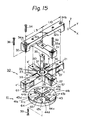
- Figures 14 and 15 illustrate an example of the supporting apparatus of the present invention, Fig. 14 being a perspective view and Fig. 15 being an exploded perspective view.
- Figure 16-(a) is a plane view of an XYZ module
- Fig. 16-(b) is a side view thereof
- Fig. 17 is a plane view of a y-module.
- reference numeral 30 represents a force-detecting module for detecting forces in the directions of the X-, Y-, and Z-axes, which is a cruciform structural body comprising angular rods 21 and 22 deformable in three directions X, Y and Z.
- Slit-like clearances a, a', b, b', c, and c' are formed by wire discharging processing, whereby parallel plate springs 23, 24, 25, 26, 27, and 28 are constructed on the angular rods 21 and 22.
- reference numerals 50, 51, 52, 53, 54, and 55 represent through holes formed in advance by a drill or the like for passing wires for wire discharging processing. These through holes are omitted in Figs. 14 and 15. These through holes 50 through 55 can be used as the wiring holes for guiding wires of the strain gauges.
- slits a through d are formed by discharging processing to form plate springs 41a through 41d, and displacement-regulating members 64 through 67 are arranged to regulate displacements of the plate springs 41a through 41d.
- Reference numerals 68 and 69 (Fig. 7) represent operation spaces for attaching strain gauges to the plate springs 41a and 41b.
- reinforcing thick portions L may be formed on the end portions of the plate springs by discharging processing, as shown in Fig. 18.
- Figure 19 illustrates the structure of the force-de- in an embodiment tecting apparatus / 6f the present invention.
- Fig. 19-(a) is a top view (view seen from the direction Z)
- Fig. 19-(b) is a view showing the section seen along the line II-II in Fig. 19-(a)
- Fig. 19-(c) is a view showing the section taken along the line III-III in Fig. 19-(a).
- the force-detecting apparatus 10 has, as 4 sides of a cruciform structure, two Y-direction parallel plate spring assemblies, each comprising a parallel plate spring 13 deformable in the direction X and a parallel plate spring 12 deformable in the direction Z, and two X-direction parallel plate spring assemblies, each comprising a parallel plate spring 11 deformable in the direction Y and a parallel plate spring 12 deformable in the direction Z.
- These parallel plate springs can be formed by forming two U-shaped slits 17 orthogonal to each other on each side of a cruciform metal block having a rectangular section by discharging processing or the like. The inner side of each U-shaped slit acts as a displacement-regulating member (stopper) 14 for each parallel plate spring.
- the parallel plate springs 11, 12 and 13 are deformed under application of a force, if they abut against the deformation-regulating members 14, they are no longer deformed. If the width of the slits is appropriately set, the deformations of the respective parallel plate springs can be controlled within the range of elastic deformation of the plate springs, and plastic deformation or breakage of the plate springs can be prevented.
- strain gauges el through e4 are attached symmetrically with respect to the center of the cruciform structure.
- strain gauges e5 through e8 are attached symmetrically with respect to the center of the side face of the cruciform body.
- this force-detecting apparatus 10 is attached to the wrist portion of a robot.
- a cruciform supporting member 19 is secured to the top end of an arm 18 of the robot, and the force-detecting apparatus 10 is supported on this supporting frame 19 through bearings 15a and 15b so that each side of the force-detecting apparatus can rotate relatively to the supporting frame.
- one bearing 15a is held on the supporting frame 19 so that only rotation is permissible, while the other bearing 15b is held on the supporting frame 19 so that the bearing 15b can rotate and slide in the axial direction.
- the displacement of the parallel plate springs can be smoothed and the sensitivity can be increased, and deviation of the central position owing to the deformation of the parallel plate springs can always be kept in a certain direction and no variation of the detected values is brought about, with the result that the detection reliability can be increased.
- the hand 20 is secured to the central portion of the cruciform force-detecting apparatus 10.
- Reference numeral 16 in Fig. 19 represents a hole for fixation of the hand.
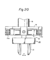
- a finger 21 (Fig.
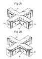
- the force-detecting apparatus 10 makes opening and closing operations in the direction of arrow K to grip an article. Since the force-detecting apparatus 10 is supported on the supporting frame 19 so that the sides in the directions X and Y of the force-detecting apparatus 10 can rotate relatively to the supporting frame 19, a torque around one axis gives no force to the supporting frame in the direction of this axis but the force is given only to the supporting frame in the direction orthogonal to this axis, and therefore, the sides of the orthogonal supporting frames do not interfere with each other. Accordingly, the respective sides of the supporting frame 19 need not be separated for prevention of mutual interference, and the supporting frame 19 can be integrally formed as shown in Fig. 21.
- Figure 22-(a) shows the state where a torque around the Y-axis is applied.
- a torque in the direction of arrow E acts on the hand 20, and two sides of the cruciform structure along the Y-axis are rotated in the direction of arrow F through bearings l5a and 15b. Accordingly, this moment in the direction E acts on the end portions of the two sides of the cruciform structure and the parallel plate springs 12 are deformed as shown in Fig. 22-(a). Therefore, the strain gauges e2 and e4 are deformed to emit outputs. Other strain gauges are not deformed and they do not emit any output.
- Figure 22-(b) shows the state where a force is applied to the hand 20 in the direction of arrow G (direction Y).
- a reaction force acts on the end portions of two sides of the cruciform structure along the X-axis through the supporting frame and the parallel plate springs 11 are deformed as shown in Fig. 22-(b). Accordingly, only the strain gauges e7 and e8 are deformed and emit outputs, while other strain gauges emit no output.
- Figure 23-(a) shows the state where a force is applied to the hand 20 in the direction of arrow H (direction Z).
- a reaction force acts on the end portions of four sides of the cruciform structure along the X-and Y-axes through the supporting frame, and four parallel plate springs 12 (only two springs are shown) are deformed as shown in Fig. 23-(a). Accordingly, the strain gauges el through e4 are deformed and emit outputs, while other strain gauges emit no output.
- Figure 23-(b) shows the state where a torque around the direction of arrow J (Z-axis) acts on the hand 20.
- a moment acts on the end portions of the four sides of the cruciform structure through the supporting frame and the parallel plate springs 11 and 13 are deformed as shown in Fig. 23-(b). Accordingly, the strain gauges e3 through e8 are deformed and emit outputs, while other strain gauges emit no output.
- the supporting frame is rigid and is not deformed.
- F stands for the force vector
- Fx, Fy, and Fz stand for force components in the directions X, Y, and Z, respectively
- Tx, Ty, and Tz stand for torque components around the X-, Y-, and Z-axes, respectively.
- € stands for the gain to be multiplied into the output voltage values of the strain gauges
- the longitudinal rows correspond to the six components of the force vector
- the lateral lines correspond to the eight strain gauges el through e8.
- E stands for the output voltage of the strain gauges.
- a torsion bar may be used instead of the bearing.
- This embodiment will now be described with reference to Figs. 24 through 28. Namely, this embodiment is the same as the embodiment shown in Figs. 19 through 23 except that torsion bars 15 are arranged as means for supporting the respective sides of the cruciform body so that they can rotate around the long axis. Other structural features and functions are the same as in the embodiment shown in Figs. 19 through 23.
- each torsion bar 15 has a screw 24 on one end thereof in the axial direction and is screwed to one end portion of the side of the force-detecting apparatus 10 through this screw.
- the torsion bar 15 has a screw hole on the other end portion and the torsion bar 15 is secured to a supporting frame 19 by a screw 22 through this screw hole and a hole 25 of the supporting frame 19.
- a tensile stress in the axial direction acts on the torsion bar 15 by the clamping force of the screw 22, and the rigidity against deflection is increased. Accordingly, the torsion bar is not deformed by force rectangular to the axis but responds only to torsional force and rotates around the axis. Since the torsion bar 15 is different from the bearing in that no frictional force acts thereon, the torsion bar 15 can respond sensitively to a slight torque and perform a high precision rotating operation.
- This force-detecting apparatus is supported on an integrally formed supporting frame 19 (see Fig. 26) as in the foregoing embodiment.
- Figures 27 and 28 show the operations of the force-detecting apparatus comprising the above-mentioned torsion bars, and these operations are not substantially different from those of the foregoing embodiment (Figs. 22 and 23).
- the apparatus when the apparatus is used for detecting an external force on a robot or the like, if a certain external force is applied to the robot, the robot can be immediately moved and driven in a direction cancelling the external force, and high-speed control of the robot becomes possible and the operation reliability of the robot is increased. Furthermore, if displacement-regulating means (stoppers) are formed together with the parallel plate springs, plastic deformation or damage of the force-detecting apparatus is not caused and the functions of the force-detecting apparatus can be exerted stably.
- Figure 29 is a perspective view illustrating still another embodiment of the present invention.
- This embodiment is constructed by improving the embodiment shown in Fig. 13 while reducing the dimensions.
- a cruciform body is constructed by four parallel plate spring assemblies 501 through 504, which are secured to supporting frames 505 and 506.
- Each parallel plate spring assembly comprises two parallel plate springs 509 and 510, the inner end portions of which are secured to a common rectangular frame 511.
- the outer end portion of one parallel plate spring 509 is secured to a supporting member 153 and the other end portion of the other parallel plate spring 510 is secured to another supporting member 514.
- This outer supporting member 514 is secured to the end portions of the supporting frames 505 and 506 arranged in the cruciform shape.
- a cubic member 507 is arranged in the central portion of the cruciform body.
- Axial rods 508 are projected outward from four sides of the cubic member 507. Each axial rod 508 is secured to the supporting member 513 through a hole 512 of the common rectangular frame 511 on the inner side of the parallel plate spring assemblies 501 through 504 (see Fig. 30).
- each parallel plate spring assembly can be made shorter than in the embodiment shown in Fig. 13, and the size of the apparatus can be diminished.
- Other structural features and functions are the same as in the embodiment shown in Fig. 13.
- Figures 31 and 32 illustrate an improvement of the aS-module 43 shown in Fig. 9.
- the displacement in the direction of the Z-axis is detected by the plate springs cl and cl' of the module 30.
- the plate spring 48 of the aB-module 45 for detecting the moments around the X- and Y-axes is slightly deformed in the direction of the Z-axis.
- Means for preventing the displacement of this plate spring 48 in the direction of the Z-axis and detecting the displacement in the direction of the Z-axis only by the parallel plate springs cl and cl' of the module 30 are shown in Figs. 31 and 32.
- a circular plate spring 48 is inserted and secured between annular supporting frames 49 and 50.
- a rigid plate 550 is secured to the top face of the supporting frame 49, and a projecting rod 552 having a rounded top end is arranged in the central portion of the rigid plate 550.
- This projecting rod 552 is fitted in a recess 553 of a receiving member 551 arranged in the central portion of the circular plate spring 48. It is preferred that the inner face of the recess 553 be rounded. If this structure is adopted, the circular plate spring 48 is not displaced in the direction of the Z-axis but is deformed only in response to torques around the X- and Y-axes. Accordingly, all the force in the direction of the Z-axis is transferred to another module for detecting the force in the direction of the Z-axis. Therefore, the detection precision can be increased.
- strain gauges are used for detecting deformations of the plate springs.
- Other detecting means for example, optical measuring means or volume measuring means, may be used for detecting deformations of plate springs.
Landscapes
- Physics & Mathematics (AREA)
- General Physics & Mathematics (AREA)
- Force Measurement Appropriate To Specific Purposes (AREA)
Applications Claiming Priority (8)
| Application Number | Priority Date | Filing Date | Title |
|---|---|---|---|
| JP59205721A JPS6183929A (ja) | 1984-09-29 | 1984-09-29 | 力検出装置 |
| JP205721/84 | 1984-09-29 | ||
| JP60057414A JPS61226285A (ja) | 1985-03-20 | 1985-03-20 | 支持装置 |
| JP57414/85 | 1985-03-20 | ||
| JP122739/85 | 1985-06-07 | ||
| JP122738/85 | 1985-06-07 | ||
| JP60122739A JPS61292029A (ja) | 1985-06-07 | 1985-06-07 | 力検出装置 |
| JP60122738A JPS61292028A (ja) | 1985-06-07 | 1985-06-07 | 力検出装置 |
Publications (3)
| Publication Number | Publication Date |
|---|---|
| EP0177284A2 true EP0177284A2 (de) | 1986-04-09 |
| EP0177284A3 EP0177284A3 (en) | 1988-12-07 |
| EP0177284B1 EP0177284B1 (de) | 1991-09-11 |
Family
ID=27463498
Family Applications (1)
| Application Number | Title | Priority Date | Filing Date |
|---|---|---|---|
| EP85306871A Expired - Lifetime EP0177284B1 (de) | 1984-09-29 | 1985-09-27 | Kraftmessvorrichtung |
Country Status (7)
| Country | Link |
|---|---|
| US (2) | US4762006A (de) |
| EP (1) | EP0177284B1 (de) |
| KR (1) | KR910000267B1 (de) |
| AU (1) | AU564927B2 (de) |
| CA (1) | CA1259816A (de) |
| DE (1) | DE3584066D1 (de) |
| ES (1) | ES8609704A1 (de) |
Cited By (3)
| Publication number | Priority date | Publication date | Assignee | Title |
|---|---|---|---|---|
| DE3937164A1 (de) * | 1989-11-08 | 1991-05-16 | Ewald Von Prof Dr Puttkamer | Verfahren und anordnung zur simultanen messung von kraeften und momenten |
| EP0617253A3 (de) * | 1993-03-20 | 1995-06-14 | Pietzsch Automatisierungstech | Messvorrichtung zum Vermessen der Form von Zylindern. |
| EP2131166A1 (de) * | 2008-06-03 | 2009-12-09 | Bilwinco A/S | Lastmesseinrichtung |
Families Citing this family (42)
| Publication number | Priority date | Publication date | Assignee | Title |
|---|---|---|---|---|
| DE3852271T2 (de) * | 1987-04-24 | 1995-07-06 | Enplas Lab Inc | Kraft- und momentendetektor unter verwendung eines widerstandes. |
| DE4012829C2 (de) * | 1990-04-23 | 1995-11-23 | Walter Rieger | Vorrichtung zur mehrdimensionalen Kraftmessung und daraus abgeleiteten Größen durch Meßwertaufnahme mittels elektrischer Sensoren, z. B. Dehnungsmeßstreifen |
| US5490427A (en) * | 1994-10-17 | 1996-02-13 | Fanuc Usa Corporation | Six axis force sensor employing multiple shear strain gages |
| US5648708A (en) * | 1995-05-19 | 1997-07-15 | Power Concepts, Inc. | Force actuated machine controller |
| US5936165A (en) * | 1997-02-18 | 1999-08-10 | Hughes Electronics Corporation | Methods for uniform heating and cooling of large objects |
| KR100480011B1 (ko) * | 2001-12-04 | 2005-03-30 | 이종한 | 스트레인 게이지를 이용한 조이스틱 |
| FR2860474B1 (fr) * | 2003-10-02 | 2006-04-28 | Bosch Gmbh Robert | Servomoteur electrique d'assistance au freinage et vehicule comportant un tel servomoteur |
| FI119889B (fi) * | 2004-07-15 | 2009-04-30 | Moventas Oy | Mittauslaitteisto vaihteiston yhteydessä |
| JP4779333B2 (ja) * | 2004-10-05 | 2011-09-28 | パナソニック株式会社 | 歪検出装置 |
| US8496647B2 (en) | 2007-12-18 | 2013-07-30 | Intuitive Surgical Operations, Inc. | Ribbed force sensor |
| DE102005033527B4 (de) * | 2005-07-14 | 2009-07-16 | Schenck Process Gmbh | Vorrichtung zur Erfassung von Kräften und/oder Momenten |
| CN100410640C (zh) * | 2005-07-27 | 2008-08-13 | 同济大学 | 变灵敏度荷载传感装置 |
| ITMI20061000A1 (it) * | 2006-05-22 | 2007-11-23 | Milano Politecnico | Giunto elastico a cerniera sferica traslante e sensore di forze e momenti perfezionato con tale giunto |
| US7516675B2 (en) * | 2007-07-03 | 2009-04-14 | Kulite Semiconductor Products, Inc. | Joystick sensor apparatus |
| US8561473B2 (en) | 2007-12-18 | 2013-10-22 | Intuitive Surgical Operations, Inc. | Force sensor temperature compensation |
| JP2010160048A (ja) * | 2009-01-08 | 2010-07-22 | Alps Electric Co Ltd | 荷重検出装置、座席および荷重センサ |
| JP5024358B2 (ja) * | 2009-01-08 | 2012-09-12 | 株式会社日本自動車部品総合研究所 | 作用力検出装置 |
| ES2773065T3 (es) * | 2010-10-15 | 2020-07-09 | Yamato Scale Co Ltd | Célula de carga con protección contra sobrecargas |
| US8606403B2 (en) | 2010-12-14 | 2013-12-10 | Harris Corporation | Haptic interface handle with force-indicating trigger mechanism |
| US8918215B2 (en) * | 2011-01-19 | 2014-12-23 | Harris Corporation | Telematic interface with control signal scaling based on force sensor feedback |
| US8918214B2 (en) | 2011-01-19 | 2014-12-23 | Harris Corporation | Telematic interface with directional translation |
| US9205555B2 (en) | 2011-03-22 | 2015-12-08 | Harris Corporation | Manipulator joint-limit handling algorithm |
| US8694134B2 (en) | 2011-05-05 | 2014-04-08 | Harris Corporation | Remote control interface |
| US8639386B2 (en) | 2011-05-20 | 2014-01-28 | Harris Corporation | Haptic device for manipulator and vehicle control |
| US9026250B2 (en) | 2011-08-17 | 2015-05-05 | Harris Corporation | Haptic manipulation system for wheelchairs |
| US8996244B2 (en) | 2011-10-06 | 2015-03-31 | Harris Corporation | Improvised explosive device defeat system |
| US8954195B2 (en) | 2012-11-09 | 2015-02-10 | Harris Corporation | Hybrid gesture control haptic system |
| US8965620B2 (en) | 2013-02-07 | 2015-02-24 | Harris Corporation | Systems and methods for controlling movement of unmanned vehicles |
| US9128507B2 (en) | 2013-12-30 | 2015-09-08 | Harris Corporation | Compact haptic interface |
| JP6476730B2 (ja) | 2014-10-21 | 2019-03-06 | セイコーエプソン株式会社 | 力検出装置及びロボット |
| US10248093B2 (en) * | 2015-12-07 | 2019-04-02 | AndrosRobotics, LLC | Compliant force control module |
| US10222278B2 (en) * | 2016-02-25 | 2019-03-05 | Massachusetts Institute Of Technology | Directional force sensing element and system |
| DE102016214434B3 (de) * | 2016-08-04 | 2018-01-11 | Dr. Doll Holding Gmbh | Kraft-Moment-Sensor für eine Robotikeinheit |
| DE102016010551B3 (de) * | 2016-08-31 | 2018-02-08 | Sensodrive Gmbh | Drehmomentsensor mit radialelastischer Momentübertragung |
| EP3526565A1 (de) * | 2016-10-17 | 2019-08-21 | Kistler Holding AG | Kraft- und momentensensor, kraftaufnehmermodul für einen solchen kraft- und momentensensor und roboter mit einem solchen kraft- und momentensensor |
| EP4481351A3 (de) | 2017-11-14 | 2025-03-05 | Intuitive Surgical Operations, Inc. | Kraftsensor mit geteilter brückenschaltung |
| US12379266B2 (en) | 2018-08-22 | 2025-08-05 | University Of Utah Research Foundation | Force and torque sensor for prosthetic and orthopedic devices |
| EP3823565A4 (de) | 2018-08-28 | 2022-04-27 | University of Utah Research Foundation | Variables getriebe für assistive prothese |
| CN120333666A (zh) | 2019-11-15 | 2025-07-18 | 直观外科手术操作公司 | 扩展桥xy力传感器 |
| EP4103133A4 (de) | 2020-03-20 | 2024-03-06 | University of Utah Research Foundation | Selbstausrichtende mechanismen bei passiven und angetriebenen exoskeletten |
| EP4174465A1 (de) | 2021-10-27 | 2023-05-03 | Canon Kabushiki Kaisha | Sensor, vorrichtung, system und herstellungsverfahren für ein produkt |
| US12584805B2 (en) * | 2022-06-29 | 2026-03-24 | Subaru Corporation | Load detection device and gain adjustment method of load detection device |
Family Cites Families (15)
| Publication number | Priority date | Publication date | Assignee | Title |
|---|---|---|---|---|
| US3915015A (en) * | 1974-03-18 | 1975-10-28 | Stanford Research Inst | Strain gauge transducer system |
| JPS53103782A (en) * | 1977-02-23 | 1978-09-09 | Kyowa Electronic Instruments | Humidity proof type convertor |
| IT1096649B (it) * | 1977-06-11 | 1985-08-26 | British Leyland Uk Ltd | Sensore di carico |
| US4125168A (en) * | 1977-08-04 | 1978-11-14 | Ormond Alfred N | Load cells for flexure isolated electronic scale |
| JPS54133176A (en) * | 1978-04-05 | 1979-10-16 | Matsushita Electric Ind Co Ltd | Load detector of electronic measuring instruments |
| US4181011A (en) * | 1978-05-11 | 1980-01-01 | Maatschappij Van Berkel's Patent N.V. | Load cell |
| JPS54158281A (en) * | 1978-06-02 | 1979-12-13 | Matsushita Electric Ind Co Ltd | Load cell |
| JPS57169643A (en) * | 1981-04-13 | 1982-10-19 | Yamato Scale Co Ltd | Load cell for multiple components of force |
| US4467661A (en) * | 1981-10-02 | 1984-08-28 | Maatschappij Van Berkel's Patent N.V. | Load cell with overload protection system |
| CA1237739A (en) * | 1982-09-21 | 1988-06-07 | Kazuo Asakawa | Supporting device |
| DE3238951C2 (de) * | 1982-10-21 | 1985-10-17 | A.M. Erichsen Gmbh, 5600 Wuppertal | Kraftaufnehmer |
| EP0117334A3 (de) * | 1982-11-09 | 1986-01-15 | EMI Limited | Für mehrere Kraftkomponenten empfindliche Vorrichtung |
| JPS6062497A (ja) * | 1983-09-14 | 1985-04-10 | 畑村 洋太郎 | 多軸力センサ |
| US4573362A (en) * | 1984-07-09 | 1986-03-04 | Eaton Corporation | Multi-axis load transducer |
| US4635479A (en) * | 1984-08-29 | 1987-01-13 | Massachusetts Institute Of Technology | Force sensing apparatus |
-
1985
- 1985-09-20 CA CA000491259A patent/CA1259816A/en not_active Expired
- 1985-09-24 US US06/779,640 patent/US4762006A/en not_active Expired - Lifetime
- 1985-09-27 EP EP85306871A patent/EP0177284B1/de not_active Expired - Lifetime
- 1985-09-27 ES ES547380A patent/ES8609704A1/es not_active Expired
- 1985-09-27 DE DE8585306871T patent/DE3584066D1/de not_active Expired - Lifetime
- 1985-09-27 AU AU48139/85A patent/AU564927B2/en not_active Ceased
- 1985-09-28 KR KR1019850007175A patent/KR910000267B1/ko not_active Expired
-
1988
- 1988-05-10 US US07/192,184 patent/US4862751A/en not_active Expired - Lifetime
Cited By (3)
| Publication number | Priority date | Publication date | Assignee | Title |
|---|---|---|---|---|
| DE3937164A1 (de) * | 1989-11-08 | 1991-05-16 | Ewald Von Prof Dr Puttkamer | Verfahren und anordnung zur simultanen messung von kraeften und momenten |
| EP0617253A3 (de) * | 1993-03-20 | 1995-06-14 | Pietzsch Automatisierungstech | Messvorrichtung zum Vermessen der Form von Zylindern. |
| EP2131166A1 (de) * | 2008-06-03 | 2009-12-09 | Bilwinco A/S | Lastmesseinrichtung |
Also Published As
| Publication number | Publication date |
|---|---|
| US4862751A (en) | 1989-09-05 |
| DE3584066D1 (de) | 1991-10-17 |
| ES8609704A1 (es) | 1986-09-01 |
| KR860002351A (ko) | 1986-04-24 |
| KR910000267B1 (ko) | 1991-01-23 |
| AU4813985A (en) | 1986-04-10 |
| AU564927B2 (en) | 1987-09-03 |
| CA1259816A (en) | 1989-09-26 |
| US4762006A (en) | 1988-08-09 |
| EP0177284A3 (en) | 1988-12-07 |
| EP0177284B1 (de) | 1991-09-11 |
| ES547380A0 (es) | 1986-09-01 |
Similar Documents
| Publication | Publication Date | Title |
|---|---|---|
| EP0177284B1 (de) | Kraftmessvorrichtung | |
| US4676002A (en) | Mechanisms to determine position and orientation in space | |
| JP2645004B2 (ja) | 多自由度マニピユレータの制御装置 | |
| EP0139307B1 (de) | Kraftsensor mit mehreren Achsen | |
| US4099409A (en) | Multi-axis load cell with arcuate flexures | |
| EP0177919B1 (de) | Verfahren zum Kalibrieren der Transformationsmatrix eines Kraftsensors | |
| US4706506A (en) | Pickup for measuring forces and torques and application of such a pickup to a follower and a gripper | |
| CN111094922B (zh) | 力传感器、扭矩传感器、力感测传感器、指尖力传感器及其制造方法 | |
| JPH06226671A (ja) | ロボットハンド制御装置 | |
| Choi et al. | A polymer-based compliant force/torque and displacement sensor with creep compensation | |
| US4092854A (en) | Multi-axis load cell | |
| US11320326B2 (en) | Force sensor and sensing element thereof | |
| JPH0433006A (ja) | ロボツトシステムの制御方法 | |
| US4650016A (en) | Automatic weighing machine with minimized angle error and moment error | |
| JPS61292029A (ja) | 力検出装置 | |
| JPS6183929A (ja) | 力検出装置 | |
| JPH0518049B2 (de) | ||
| US5924214A (en) | Length measuring apparatus for measuring the relative position of two objects | |
| JPS61292028A (ja) | 力検出装置 | |
| JPH01119731A (ja) | 多軸力覚センサ | |
| JPS61264414A (ja) | 移動体制御装置 | |
| JPS6378034A (ja) | 力検出装置 | |
| JPH041540A (ja) | 力覚センサ | |
| JPH02159530A (ja) | 力センサ | |
| Ko et al. | Active force feedback control for assembly processes using a flexible and sensible robot wrist |
Legal Events
| Date | Code | Title | Description |
|---|---|---|---|
| PUAI | Public reference made under article 153(3) epc to a published international application that has entered the european phase |
Free format text: ORIGINAL CODE: 0009012 |
|
| AK | Designated contracting states |
Kind code of ref document: A2 Designated state(s): BE CH DE FR GB IT LI NL SE |
|
| PUAL | Search report despatched |
Free format text: ORIGINAL CODE: 0009013 |
|
| AK | Designated contracting states |
Kind code of ref document: A3 Designated state(s): BE CH DE FR GB IT LI NL SE |
|
| 17P | Request for examination filed |
Effective date: 19890202 |
|
| 17Q | First examination report despatched |
Effective date: 19900622 |
|
| ITF | It: translation for a ep patent filed | ||
| GRAA | (expected) grant |
Free format text: ORIGINAL CODE: 0009210 |
|
| AK | Designated contracting states |
Kind code of ref document: B1 Designated state(s): BE CH DE FR GB IT LI NL SE |
|
| REF | Corresponds to: |
Ref document number: 3584066 Country of ref document: DE Date of ref document: 19911017 |
|
| ET | Fr: translation filed | ||
| PLBE | No opposition filed within time limit |
Free format text: ORIGINAL CODE: 0009261 |
|
| STAA | Information on the status of an ep patent application or granted ep patent |
Free format text: STATUS: NO OPPOSITION FILED WITHIN TIME LIMIT |
|
| 26N | No opposition filed | ||
| EAL | Se: european patent in force in sweden |
Ref document number: 85306871.6 |
|
| PGFP | Annual fee paid to national office [announced via postgrant information from national office to epo] |
Ref country code: FR Payment date: 19970909 Year of fee payment: 13 |
|
| PGFP | Annual fee paid to national office [announced via postgrant information from national office to epo] |
Ref country code: SE Payment date: 19970918 Year of fee payment: 13 Ref country code: GB Payment date: 19970918 Year of fee payment: 13 |
|
| PGFP | Annual fee paid to national office [announced via postgrant information from national office to epo] |
Ref country code: NL Payment date: 19970929 Year of fee payment: 13 |
|
| PGFP | Annual fee paid to national office [announced via postgrant information from national office to epo] |
Ref country code: CH Payment date: 19971007 Year of fee payment: 13 |
|
| PGFP | Annual fee paid to national office [announced via postgrant information from national office to epo] |
Ref country code: DE Payment date: 19971010 Year of fee payment: 13 |
|
| PGFP | Annual fee paid to national office [announced via postgrant information from national office to epo] |
Ref country code: BE Payment date: 19971118 Year of fee payment: 13 |
|
| PG25 | Lapsed in a contracting state [announced via postgrant information from national office to epo] |
Ref country code: GB Free format text: LAPSE BECAUSE OF NON-PAYMENT OF DUE FEES Effective date: 19980927 |
|
| PG25 | Lapsed in a contracting state [announced via postgrant information from national office to epo] |
Ref country code: SE Free format text: LAPSE BECAUSE OF NON-PAYMENT OF DUE FEES Effective date: 19980928 |
|
| PG25 | Lapsed in a contracting state [announced via postgrant information from national office to epo] |
Ref country code: LI Free format text: LAPSE BECAUSE OF NON-PAYMENT OF DUE FEES Effective date: 19980930 Ref country code: CH Free format text: LAPSE BECAUSE OF NON-PAYMENT OF DUE FEES Effective date: 19980930 Ref country code: BE Free format text: LAPSE BECAUSE OF NON-PAYMENT OF DUE FEES Effective date: 19980930 |
|
| BERE | Be: lapsed |
Owner name: FUJITSU LTD Effective date: 19980930 |
|
| PG25 | Lapsed in a contracting state [announced via postgrant information from national office to epo] |
Ref country code: NL Free format text: LAPSE BECAUSE OF NON-PAYMENT OF DUE FEES Effective date: 19990401 |
|
| REG | Reference to a national code |
Ref country code: CH Ref legal event code: PL |
|
| GBPC | Gb: european patent ceased through non-payment of renewal fee |
Effective date: 19980927 |
|
| EUG | Se: european patent has lapsed |
Ref document number: 85306871.6 |
|
| PG25 | Lapsed in a contracting state [announced via postgrant information from national office to epo] |
Ref country code: FR Free format text: LAPSE BECAUSE OF NON-PAYMENT OF DUE FEES Effective date: 19990531 |
|
| NLV4 | Nl: lapsed or anulled due to non-payment of the annual fee |
Effective date: 19990401 |
|
| PG25 | Lapsed in a contracting state [announced via postgrant information from national office to epo] |
Ref country code: DE Free format text: LAPSE BECAUSE OF NON-PAYMENT OF DUE FEES Effective date: 19990701 |
|
| REG | Reference to a national code |
Ref country code: FR Ref legal event code: ST |