EP0177461A2 - Appareil pour la lecture d'information graphique affichée sur un substrat - Google Patents
Appareil pour la lecture d'information graphique affichée sur un substrat Download PDFInfo
- Publication number
- EP0177461A2 EP0177461A2 EP85830241A EP85830241A EP0177461A2 EP 0177461 A2 EP0177461 A2 EP 0177461A2 EP 85830241 A EP85830241 A EP 85830241A EP 85830241 A EP85830241 A EP 85830241A EP 0177461 A2 EP0177461 A2 EP 0177461A2
- Authority
- EP
- European Patent Office
- Prior art keywords
- sheet
- reading
- sensors
- substrate
- carriage
- Prior art date
- Legal status (The legal status is an assumption and is not a legal conclusion. Google has not performed a legal analysis and makes no representation as to the accuracy of the status listed.)
- Granted
Links
Images

Classifications
-
- H—ELECTRICITY
- H04—ELECTRIC COMMUNICATION TECHNIQUE
- H04N—PICTORIAL COMMUNICATION, e.g. TELEVISION
- H04N1/00—Scanning, transmission or reproduction of documents or the like, e.g. facsimile transmission; Details thereof
- H04N1/04—Scanning arrangements, i.e. arrangements for the displacement of active reading or reproducing elements relative to the original or reproducing medium, or vice versa
- H04N1/06—Scanning arrangements, i.e. arrangements for the displacement of active reading or reproducing elements relative to the original or reproducing medium, or vice versa using cylindrical picture-bearing surfaces, i.e. scanning a main-scanning line substantially perpendicular to the axis and lying in a curved cylindrical surface
- H04N1/0671—Scanning arrangements, i.e. arrangements for the displacement of active reading or reproducing elements relative to the original or reproducing medium, or vice versa using cylindrical picture-bearing surfaces, i.e. scanning a main-scanning line substantially perpendicular to the axis and lying in a curved cylindrical surface with sub-scanning by translational movement of the main-scanning components
-
- H—ELECTRICITY
- H04—ELECTRIC COMMUNICATION TECHNIQUE
- H04N—PICTORIAL COMMUNICATION, e.g. TELEVISION
- H04N1/00—Scanning, transmission or reproduction of documents or the like, e.g. facsimile transmission; Details thereof
- H04N1/024—Details of scanning heads ; Means for illuminating the original
- H04N1/028—Details of scanning heads ; Means for illuminating the original for picture information pick-up
- H04N1/03—Details of scanning heads ; Means for illuminating the original for picture information pick-up with photodetectors arranged in a substantially linear array
-
- H—ELECTRICITY
- H04—ELECTRIC COMMUNICATION TECHNIQUE
- H04N—PICTORIAL COMMUNICATION, e.g. TELEVISION
- H04N1/00—Scanning, transmission or reproduction of documents or the like, e.g. facsimile transmission; Details thereof
- H04N1/04—Scanning arrangements, i.e. arrangements for the displacement of active reading or reproducing elements relative to the original or reproducing medium, or vice versa
- H04N1/06—Scanning arrangements, i.e. arrangements for the displacement of active reading or reproducing elements relative to the original or reproducing medium, or vice versa using cylindrical picture-bearing surfaces, i.e. scanning a main-scanning line substantially perpendicular to the axis and lying in a curved cylindrical surface
-
- H—ELECTRICITY
- H04—ELECTRIC COMMUNICATION TECHNIQUE
- H04N—PICTORIAL COMMUNICATION, e.g. TELEVISION
- H04N1/00—Scanning, transmission or reproduction of documents or the like, e.g. facsimile transmission; Details thereof
- H04N1/04—Scanning arrangements, i.e. arrangements for the displacement of active reading or reproducing elements relative to the original or reproducing medium, or vice versa
- H04N1/19—Scanning arrangements, i.e. arrangements for the displacement of active reading or reproducing elements relative to the original or reproducing medium, or vice versa using multi-element arrays
- H04N1/191—Scanning arrangements, i.e. arrangements for the displacement of active reading or reproducing elements relative to the original or reproducing medium, or vice versa using multi-element arrays the array comprising a one-dimensional [1D] array
- H04N1/1911—Simultaneously or substantially simultaneously scanning picture elements on more than one main scanning line, e.g. scanning in swaths
-
- H—ELECTRICITY
- H04—ELECTRIC COMMUNICATION TECHNIQUE
- H04N—PICTORIAL COMMUNICATION, e.g. TELEVISION
- H04N2201/00—Indexing scheme relating to scanning, transmission or reproduction of documents or the like, and to details thereof
- H04N2201/024—Indexing scheme relating to scanning, transmission or reproduction of documents or the like, and to details thereof deleted
- H04N2201/02406—Arrangements for positioning elements within a head
- H04N2201/02427—Element positioned
- H04N2201/02429—Photodetector element, e.g. CCD array
-
- H—ELECTRICITY
- H04—ELECTRIC COMMUNICATION TECHNIQUE
- H04N—PICTORIAL COMMUNICATION, e.g. TELEVISION
- H04N2201/00—Indexing scheme relating to scanning, transmission or reproduction of documents or the like, and to details thereof
- H04N2201/024—Indexing scheme relating to scanning, transmission or reproduction of documents or the like, and to details thereof deleted
- H04N2201/02406—Arrangements for positioning elements within a head
- H04N2201/02427—Element positioned
- H04N2201/02431—Lens or optical system
-
- H—ELECTRICITY
- H04—ELECTRIC COMMUNICATION TECHNIQUE
- H04N—PICTORIAL COMMUNICATION, e.g. TELEVISION
- H04N2201/00—Indexing scheme relating to scanning, transmission or reproduction of documents or the like, and to details thereof
- H04N2201/024—Indexing scheme relating to scanning, transmission or reproduction of documents or the like, and to details thereof deleted
- H04N2201/02452—Arrangements for mounting or supporting elements within a scanning head
- H04N2201/02454—Element mounted or supported
- H04N2201/02462—Illuminating means
-
- H—ELECTRICITY
- H04—ELECTRIC COMMUNICATION TECHNIQUE
- H04N—PICTORIAL COMMUNICATION, e.g. TELEVISION
- H04N2201/00—Indexing scheme relating to scanning, transmission or reproduction of documents or the like, and to details thereof
- H04N2201/024—Indexing scheme relating to scanning, transmission or reproduction of documents or the like, and to details thereof deleted
- H04N2201/02452—Arrangements for mounting or supporting elements within a scanning head
- H04N2201/02479—Mounting or supporting means
- H04N2201/02485—Dedicated element, e.g. bracket or arm
-
- H—ELECTRICITY
- H04—ELECTRIC COMMUNICATION TECHNIQUE
- H04N—PICTORIAL COMMUNICATION, e.g. TELEVISION
- H04N2201/00—Indexing scheme relating to scanning, transmission or reproduction of documents or the like, and to details thereof
- H04N2201/04—Scanning arrangements
- H04N2201/0402—Arrangements not specific to a particular one of the scanning methods covered by groups H04N1/04 - H04N1/207
- H04N2201/0442—Details of scanning carriage or moving picture-bearing surface support, e.g. bearing contact with guide rails
Definitions
- This invention relates to devices for reading graphic information on a substrate in the form of, for example, a sheet.
- Such devices are currently used in readers for facsimile or for Optical Character Recognition (OCR) or as an input unit for processor systems designed to memorise signatures, graphic symbols, drawings, mathematical symbols, etc., or for the scanning of an original in document copying machines.
- OCR Optical Character Recognition
- the object of this invention is to provide a device for reading graphic information on a substrate, which will avoid the disadvantages referred to and which can easily be used in conjunction with an operating unit of a simplified kind.
- this invention provides a device of the above specified kind characterised in that it comprises:
- the device according to the invention comprises an array of sensors each able to generate an electrical signal the level of which is indicative of the level of luminosity of the image of a respective elemental area of the portion of the substrate being scanned at that moment by the reading device.
- a reading device which is of compact structure and small dimensions, so as to permit its mounting on the head-carrying carriage of a typewriter or a printing machine of the type currently associated with electronic processors, personal computers, video terminals, etc.
- the reading device described above is incorporated into an apparatus for reading graphic information on a sheet substrate carried on a cylindrical drum and means for advancing the drum in successive rotational steps of the drum to effect progressive longitudinal advance of the sheet applied to the drum, and a carriage movable in the direction of the axis of the drum and able to effect, upon each rotational step of the said drum, a transverse displacement of the sheet; the said reading device being mounted upon the said carriage, whereby, in use, the reading device scans sequentially successive surface portions of the sheet applied to the drum.
- the device above described is incorporated in an apparatus for reading graphic information on a sheet which can moreover effect reproduction of the graphic information read from the said sheet on to another sheet fed successively to the apparatus.
- the invention thus makes it possible to produce, in a particularly simple and economical way, and making use partly of components currently in production, such as the roller-head-carrying carriage units of typewriters or printing machines currently in production, readers for facsimile or OCR, input devices for memorising signatures, graphic symbols, drawings and mathematical symbols and equipment for (local) copying of documents.
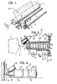
- Figure 1 illustrates diagrammatically, and partially, the structure of an apparatus for reading graphic information on a substrate consisting of a sheet F upon which there are printed, typed, handwritten or recorded by any photographic or typographic techniques, characters, graphical signs or symbols of another kind.
- graphic information shown as S, are designated generally as "graphic information”.
- Reference 1 indicates generally a drum to which the sheet F carrying the graphic information to be read is applied.
- the drum 1 can be selectively rotated about its main axis 2 by a motorised drive unit of known type (not illustrated).
- rotation of the drum 1 is effected in successive angular steps, each of which advances the sheet F longitudinally by an amount corresponding to one line of writing or printing, or to a fraction of such a line.
- a carriage indicated generally 8 is movable transversely in alternating movement relative to the sheet F.
- the movement of the carriage 8 is guided by a bush 8a slidable along a cylindrical guide bar 5 fixed to the sides of the housing of the apparatus (not shown in the drawings) and the longitudinal axis of which is parallel to the axis of rotation of the drum 1.
- the carriage 8 also bears, through a pad 8b, upon a second cylindrical guide bar 7, fixed to the sides of the housing of the apparatus, parallel to the guide bar 5.
- the pad 8b is connected to the carriage 8 through a telescopic joint 6, within which a compression spring 3 is housed. This latter normally holds a spacer 4 against the drum 1, whereby the carriage 8 is maintained at a constant distance from the sheet F.
- motor means Associated with the carriage 8 are motor means (not shown) which allow the carriage to be given a fast alternating running movement along the guides 5 and 7.
- the structure described is therefore substantially identical to the structure of the transport units of the printing head of printers or of typewriters currently in production.
- the carriage 8 can effect a scanning movement of the sheet F. This movement brings the carriage into register successively with surface portions of the sheet F ordinately adjacent each other.
- the device 10 is therefore able to perform a coordinated scanning action of the surface of the sheet F carrying the graphic information S to be read.
- the device 10 In its general configuration, common both to the embodiment of Figure 2 and to the variant of Figures 3 and 4, the device 10 has a housing and support body 11 of moulded plastics material provided with flanges or like connecting elements which permit its assembly upon the carriage 8. Flanges 12, provided with holes 13 for the passage of fixing screws, can be more plainly seen in the variant of Figures 3 and 4.
- each tubular part 15 has at its free end a tubular part 15 provided with a longitudinal slot 15a which imparts to this part 15 a certain radial elastic yieldability.
- the main axis of each tubular part 15 intersects, ideally, the main axes of the tubular parts 15 provided on the other bracket elements 14 at a point H.
- the light sources 16 are fed from an electrical power supply (not illustrated) through electrical conductors attached to the body 11 and not plainly visible in the drawings.
- the sources 16 When activated, the sources 16 project respective light beams which converge onto that region of the sheet F at which - at that moment - the point H is located.
- each bracket element 14 constitutes a separate piece mounted on the body 11 by means of a screw 114, in such a way that, by rotating the bracket element 14 about the axis of the screw 114, it is possible to adjust with precision the relative position of the respective source 16 relative to the body 11 and to the point H on the drum 1.
- bracket elements 14 and the tubular parts 15 constitute integral appendages of the body 11, made from moulded plastics material.
- annular recess which forms a mounting seat for a lens 17 of glass or plastics material.
- the lens 17 is mounted closely adjacent the sources 16 and is so arranged that the focal axis of the lens 17 passes through the point of convergence H of the radiation beams emitted by the sources 16.
- the distance between the device 10 and the surface of the drum 1, that is to say, the distance between the device 10 and the surface of the sheet F, is so adjusted that the lens 17 forms, in a predetermined plane, indicated B in the drawings, a flat image of the surface portion of the sheet F which the device 10 is at that moment facing.
- the lens 17 "frames" that portion of the sheet F which at that moment is illuminated by the sources 16, forming in the plane B a flat image of that portion of the sheet.
- the image formed in the plane B will have dark (low luminosity) areas corresponding to those areas of the sheet covered by ink and light (high luminosity) areas corresponding to the "white" areas of the sheet.
- the image formed in the plane B will have areas exhibiting corresponding levels of intermediate luminosity.
- the image formed in the plane B can ideally be subdivided into elemental areas, each of which has a level of luminosity corresponding to the level of luminosity of a corresponding elemental area of the portion of sheet F at that moment being viewed by the lens 17.
- the level of luminosity of each of these elemental areas and of the respective image in the plane B corresponds in fact to the intensity of that fraction of the light emitted by the sources 16 which is reflected by the said elemental area.
- the array 18 is so oriented that, when the device 10 is mounted upon the carriage 8, the direction of alignment of the sensors will be orthogonal to the direction of movement of the carriage 8 on the guides 5 and 7.
- This sensor arrangement permits the operation of reading the graphic information to be carried out in a way which allows its subsequent reproduction with a point matrix printing device.
- the array 18 of sensors can be formed by an array of photodiodes or phototransistors or by an array of CCD (Charge Coupled Devices).
- the position of the lens 17 relative to the point H, the position of the plane B relative to the lens 17, and the optical characteristics of the lens can be so selected that the image formed in the plane B constitutes an enlarged or reduced image, or an image with magnification of only that portion of the sheet F being viewed at the moment by the lens 17.
- the optical system consisting of the lens 17 and the sensors of the array 18 will normally be made in such manner that a single transducer of the array 18 is illuminated by the light reflected by a single corresponding elemental area of that portion of the sheet being scanned.
- arrays of CCD which usually have smaller sensing surfaces
- Figure 5 there is illustrated diagrammatically the structure of a linear array 18 of photodiodes which can be used in the fabrication of the reader device 11.
- the array 18 of sensors has eight sensing areas or pixel elements 19, rectangular in shape with dimensions of 0.33 x 0.24 mm.
- the sensors of the array 18 have a sensitivity of the order of about 0.5A/W at a wavelength of about 790 nm with a maximum sensitivity at about 820 nm.
- the cross-talk between adjacent sensors is less than 3% of the maximum signal picked up by the sensors.
- the body 11 In the region between the lens 17 and the photodiode array 18, the body 11 has a tubular duct 20 which encloses the volume in which light is propagated from the lens 17 towards the photosensor array 18. This arrangement is intended to minimise the influence of ambient luminosity on the reading quality.
- the duct 20 consists of two tubular elements 20a and 20b coupled together telescopically.
- the duct section 20a disposed in front of the housing body, is provided at the end located adjacent the bracket elements 14 with the annular recess in which the lens 17 is mounted.
- the corresponding terminal edge of the duct section 20a has a flange part 21 which extends partially over the face of the lens 17 which faces towards the outside of the body 11.
- the flange part 21 acts as a stop and as a resilient element for the mechanical retention of the lens 17 in the respective annular recess.
- the element 22 has an elongate opening or slot 23 through which a fixing screw 24 extends, the screw 24 being received in a corresponding threaded hole in the body 11.
- the position of the body 11, and hence of the duct section 20a and of the lens 17 fixed to it, is fixed in an adjustable manner relative to the point H by slots 14a, 14b and 14c in which respective fixing screws engage.
- the position of the duct section 20b, and of the sensor array fixed to it, is adjustable relative to the lens 17 by sliding the duct section axially by virtue of the slot 23 and the telescopic coupling with the duct section 20a.
- the duct section 20b is locked by tightening the screw 24.
- the tubular duct 20 consists of a shaped part of the housing body 11, integral with the bracket elements 14 which support the light sources.
- the duct 20 terminates at the end facing towards the bracket elements 14 in a flange part 21 forming a seat for positioning on the outer face of the lens 17 and acting as a stop and as a resilient retaining element for the lens.
- the internal surface of the duct 20 has, moreover, annular corrugations 120 designed to minimise phenomena of reflection of light within the duct.
- the reader device according to the embodiment of Figure 3 is thus not provided with any means for adjusting the position of the sensor array 18.
- the lenses 17 used are selected with a narrow range of variation of focal length.
- the most critical operating situation occurs in the case in which there exists a unique inter-relation between the sensors of the array 18 and the elemental areas into which, ideally, the portion of sheet F viewed by the lens 17 is subdivided.
- each elemental area of the sheet is conveyed by the lens 17 towards the sensor array 18, where it is incident on a corresponding sensor.
- This sensor outputs an electrical current or voltage signal the level of which is proportional to the intensity of the light which impinges on it, and hence to the level of luminosity of the corresponding elemental area.
- Each sensor of the array 18 emits an electrical analog signal which is compared with a reference level and converted into a binary numerical signal in the case of black and white reading.
- the reference levels are those of the grey tones under consideration.
- This conversion operation is effected, in a known way, by an analog/digital converter which generates from the analog signals provided by the sensors of the array 18, strings of binary signals constituting a numercial reading of the graphic information on the sheet F.
- the converter can also effect a processing operation upon the said strings of binary signals so as to vary the reading resolution without having to vary the geometry of the reading device 10.
- This operation can be carried out by effecting a "decimation” or an “interpolation” of the samples obtained from the analog signals emitted by the sensors of the array 18.
- the array 18 consists of CCDs with a scanned sensor/elemental area ratio greater than one, it is possible to vary the reading resolution by varying the sampling frequency of the analog signal at the output of the CCDs, or by using exclusively the signals provided by transducers spaced according to the selected resolution.
- CCDs or photodiode arrays are used in unique inter-relation with the elemental areas scanned, one can vary the reading resolution by re-sampling the analog signal output by the array 18, for example by an analog multiplexer.
- the signals are sent to the unit (modem) which effects the distant transmission of the said signals.
- such signals can be sent to processor units which store, process and possibly reproduce them on a video terminal or on a printing unit.
- processor units which store, process and possibly reproduce them on a video terminal or on a printing unit.
- the signals emitted by the converter can be subjected to a verisimilitude test aimed at recognition of the said signature.
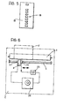
- Figure 6 illustrates diagrammatically the structure of a machine for the (local) reproduction of documents.
- the reader device 10 is mounted upon a carriage 8 movable longitudinally relative to a drum 1 for supporting and advancing the sheets 1, with a configuration similar to that illustrated in Figure 1.
- the analog signals emitted by the photoelectric sensors of the device 10 are sent to an analog/digital converter 25 which, after having converted them into numerical signals, and having possibly subjected them to other processing operations (changing of the resolution, etc....) transmits them to a memory unit 26 consisting, for example, of a small disk memory.
- the memory 26 controls, through control and actuating devices of known type, currently mounted on printers and typewriters of sophisticated type in standard production, the operation of a printer head 27 mounted on the carriage 8 adjacent the reader device 10.
- the sheet carrying the graphic information which it is desired to reproduce (“original" sheet) is applied to the drum 1 according to the criteria normally used in printers and in typewriters.
- the device 10 scans the surface of the sheet and the converter 25 generates corresponding numerical reading signals which are stored in the memory 26.
- the "original" sheet is removed from the drum 1 and replaced by a blank sheet upon which it is wished to reproduce the graphic information previously read.
- the operation of the apparatus thus proceeds according to operating criteria currently in use in printing machines and in typewriters provided with memories.
- the numerical signals stored in the memory 26 are transmitted in an ordered sequence to the printing head 27 which effects an overlapped line scanning movement over the new sheet by virtue of the coordinated movement of the drum 1 and of the carriage 8.
- the printing head 27 effects an overlapped line scanning movement over the new sheet by virtue of the coordinated movement of the drum 1 and of the carriage 8.
Landscapes
- Engineering & Computer Science (AREA)
- Multimedia (AREA)
- Signal Processing (AREA)
- Facsimile Scanning Arrangements (AREA)
- Character Input (AREA)
Applications Claiming Priority (2)
| Application Number | Priority Date | Filing Date | Title |
|---|---|---|---|
| IT6798284 | 1984-10-03 | ||
| IT67982/84A IT1182309B (it) | 1984-10-03 | 1984-10-03 | Dispositivo ed apparecchiatura per la lettura dell informazione grafica presente su un supproto |
Publications (4)
| Publication Number | Publication Date |
|---|---|
| EP0177461A2 true EP0177461A2 (fr) | 1986-04-09 |
| EP0177461A3 EP0177461A3 (en) | 1987-05-20 |
| EP0177461B1 EP0177461B1 (fr) | 1989-08-16 |
| EP0177461B2 EP0177461B2 (fr) | 1992-07-29 |
Family
ID=11306925
Family Applications (1)
| Application Number | Title | Priority Date | Filing Date |
|---|---|---|---|
| EP85830241A Expired - Lifetime EP0177461B2 (fr) | 1984-10-03 | 1985-09-24 | Appareil pour la lecture d'information graphique affichée sur un substrat |
Country Status (5)
| Country | Link |
|---|---|
| US (1) | US4683501A (fr) |
| EP (1) | EP0177461B2 (fr) |
| JP (1) | JPS61105167A (fr) |
| DE (1) | DE3572435D1 (fr) |
| IT (1) | IT1182309B (fr) |
Cited By (6)
| Publication number | Priority date | Publication date | Assignee | Title |
|---|---|---|---|---|
| EP0223957A1 (fr) * | 1985-10-24 | 1987-06-03 | DR.-ING. RUDOLF HELL GmbH | Sonde de balayage opto-électronique |
| GB2194410A (en) * | 1986-05-20 | 1988-03-02 | Sharp Kk | Image reading unit |
| GB2198009A (en) * | 1986-09-19 | 1988-06-02 | Richard Mark Charles | Converting data for facsimile transmission |
| EP0344499A3 (fr) * | 1988-06-03 | 1990-08-29 | Buderus Sell GmbH | Procédé d'analyse de modèles de textile au moyen d'un système d'analyse X-Y et dispositif pour la mise en oeuvre du procédé |
| EP3527968A1 (fr) * | 2018-02-15 | 2019-08-21 | Ricoh Company, Ltd. | Appareil d'acquisition de caractéristique spectrale, appareil de formation d'images, système de formation d'images, système de gestion d'appareil de formation d'images et procédé de gestion d'appareil de formation d'images |
| CN112668372A (zh) * | 2019-10-16 | 2021-04-16 | 株式会社日立制作所 | 字符识别方法和字符识别装置 |
Families Citing this family (8)
| Publication number | Priority date | Publication date | Assignee | Title |
|---|---|---|---|---|
| JPS6346065A (ja) * | 1986-08-13 | 1988-02-26 | Fuji Photo Film Co Ltd | 画像倍率変更方法 |
| US5070410A (en) * | 1989-03-21 | 1991-12-03 | Hewlett-Packard Company | Apparatus and method using a combined read/write head for processing and storing read signals and for providing firing signals to thermally actuated ink ejection elements |
| EP0641115B1 (fr) * | 1993-08-30 | 1999-03-24 | Hewlett-Packard Company | Tête de balayage d'image pour imprimante à jet d'encre thermique |
| US5532825A (en) * | 1993-08-30 | 1996-07-02 | Hewlett-Packard Company | Add-on scanner for existing ink jet printer |
| JPH09284471A (ja) * | 1996-04-18 | 1997-10-31 | Canon Inc | スキャナヘッドカートリッジとその使用方法、該スキャナヘッドカートリッジを用いた情報処理装置 |
| KR100224600B1 (ko) * | 1996-10-21 | 1999-10-15 | 윤종용 | 인쇄용지건조 및 독취 겸용 램프를 구비한 복합기 |
| US5829881A (en) * | 1997-04-25 | 1998-11-03 | Eastman Kodak Company | Wear resistant apparatus and method for translating a printing element relative to a frame |
| US5755520A (en) * | 1997-04-25 | 1998-05-26 | Eastman Kodak Company | Wear resistant lathe bed scanning apparatus and method |
Family Cites Families (9)
| Publication number | Priority date | Publication date | Assignee | Title |
|---|---|---|---|---|
| US1828000A (en) * | 1928-11-26 | 1931-10-20 | Rca Corp | Analyzing system for picture transmission |
| US3483385A (en) * | 1966-05-09 | 1969-12-09 | Bendix Corp | Apparatus for comparing the surface reflectivity of materials |
| US3535525A (en) * | 1967-01-31 | 1970-10-20 | Perkin Elmer Corp | Apparatus for sensing the centroid of an impinging laser light beam |
| US3684889A (en) * | 1970-02-11 | 1972-08-15 | Electronic Transmission System | Optical system for facsimile scanners and the like |
| US3735094A (en) * | 1972-07-03 | 1973-05-22 | Addressograph Multigraph | Optical code reading system |
| JPS5941628B2 (ja) * | 1979-08-29 | 1984-10-08 | 日本電信電話株式会社 | 送受兼用ヘッド |
| DE3269059D1 (en) * | 1981-06-26 | 1986-03-27 | Fujitsu Ltd | Optical reader |
| US4523235A (en) * | 1982-01-11 | 1985-06-11 | Jan Rajchman | Electronic microcopier apparatus |
| IT1212977B (it) * | 1983-02-10 | 1989-12-07 | Olivetti & Co Spa | Macchina copiatrice elettrofotogra fica |
-
1984
- 1984-10-03 IT IT67982/84A patent/IT1182309B/it active
-
1985
- 1985-09-24 DE DE8585830241T patent/DE3572435D1/de not_active Expired
- 1985-09-24 EP EP85830241A patent/EP0177461B2/fr not_active Expired - Lifetime
- 1985-10-02 JP JP60219968A patent/JPS61105167A/ja active Pending
- 1985-10-03 US US06/783,352 patent/US4683501A/en not_active Expired - Fee Related
Cited By (10)
| Publication number | Priority date | Publication date | Assignee | Title |
|---|---|---|---|---|
| EP0223957A1 (fr) * | 1985-10-24 | 1987-06-03 | DR.-ING. RUDOLF HELL GmbH | Sonde de balayage opto-électronique |
| US4742401A (en) * | 1985-10-24 | 1988-05-03 | Dr. Ing. Rudolf Hell Gmbh | Opto-electronic scan head which has a housing portion and a housing member that are coupled together by first and second guide rods so as to allow relative motion therebetween |
| GB2194410A (en) * | 1986-05-20 | 1988-03-02 | Sharp Kk | Image reading unit |
| US4839730A (en) * | 1986-05-20 | 1989-06-13 | Sharp Kabushiki Kaisha | Image reading apparatus |
| GB2194410B (en) * | 1986-05-20 | 1990-05-09 | Sharp Kk | Image reading apparatus |
| GB2198009A (en) * | 1986-09-19 | 1988-06-02 | Richard Mark Charles | Converting data for facsimile transmission |
| EP0344499A3 (fr) * | 1988-06-03 | 1990-08-29 | Buderus Sell GmbH | Procédé d'analyse de modèles de textile au moyen d'un système d'analyse X-Y et dispositif pour la mise en oeuvre du procédé |
| EP3527968A1 (fr) * | 2018-02-15 | 2019-08-21 | Ricoh Company, Ltd. | Appareil d'acquisition de caractéristique spectrale, appareil de formation d'images, système de formation d'images, système de gestion d'appareil de formation d'images et procédé de gestion d'appareil de formation d'images |
| US10564038B2 (en) | 2018-02-15 | 2020-02-18 | Ricoh Company, Ltd. | Spectral characteristic acquiring apparatus, image forming apparatus, image forming system, image forming apparatus management system, and image forming apparatus management method |
| CN112668372A (zh) * | 2019-10-16 | 2021-04-16 | 株式会社日立制作所 | 字符识别方法和字符识别装置 |
Also Published As
| Publication number | Publication date |
|---|---|
| IT1182309B (it) | 1987-10-05 |
| DE3572435D1 (en) | 1989-09-21 |
| US4683501A (en) | 1987-07-28 |
| EP0177461A3 (en) | 1987-05-20 |
| EP0177461B1 (fr) | 1989-08-16 |
| IT8467982A0 (it) | 1984-10-03 |
| IT8467982A1 (it) | 1986-04-03 |
| JPS61105167A (ja) | 1986-05-23 |
| EP0177461B2 (fr) | 1992-07-29 |
Similar Documents
| Publication | Publication Date | Title |
|---|---|---|
| US5381245A (en) | X-ray film scanning and digitizing apparatus | |
| US4683501A (en) | Apparatus for reading and reproducing graphic information | |
| US5280368A (en) | Fixed full width array scan head calibration apparatus | |
| US4587621A (en) | Device for electrical variable magnification of document image | |
| US4532602A (en) | Device for electrical variable magnification of document image | |
| JP2801284B2 (ja) | 電子写真式複写機 | |
| JPH09139812A (ja) | 文書スキャナ | |
| US5267056A (en) | Right reading image for read/write components co-mounted on a single X-Y carriage | |
| US6522431B1 (en) | System for minimizing image defects in a hard-copy input scanner | |
| EP0115366B1 (fr) | Dispositif pour l'analyse optique d'un document | |
| US4327287A (en) | Laser scanning apparatus | |
| US7164507B2 (en) | Image input terminal | |
| JPH0646192A (ja) | 用紙位置決め装置 | |
| US5187588A (en) | Scanner with floating backstop | |
| US5875043A (en) | Optical scanner for detecting light intensity from reflected image-reading light | |
| EP0428371B1 (fr) | Commande de transport du chariot d'analyse d'un dispositif d'entrée d'images | |
| US5663554A (en) | Weak lens focus adjusting mechanism based upon thickness of scanned material and imagesetter using same | |
| JP3230850B2 (ja) | 画像読取装置 | |
| GB2306270A (en) | Document reading device | |
| EP0333320A2 (fr) | Appareil pour la lecture par analyse de documents de différents formats | |
| JPH0710088B2 (ja) | 画像読取装置 | |
| JPH0320949B2 (fr) | ||
| JP2709164B2 (ja) | 光学式読取装置 | |
| JPH08184774A (ja) | 画像形成装置 | |
| JP3061498B2 (ja) | イメージセンサ |
Legal Events
| Date | Code | Title | Description |
|---|---|---|---|
| PUAI | Public reference made under article 153(3) epc to a published international application that has entered the european phase |
Free format text: ORIGINAL CODE: 0009012 |
|
| AK | Designated contracting states |
Kind code of ref document: A2 Designated state(s): DE FR GB |
|
| PUAL | Search report despatched |
Free format text: ORIGINAL CODE: 0009013 |
|
| AK | Designated contracting states |
Kind code of ref document: A3 Designated state(s): DE FR GB |
|
| 17P | Request for examination filed |
Effective date: 19871030 |
|
| 17Q | First examination report despatched |
Effective date: 19880830 |
|
| GRAA | (expected) grant |
Free format text: ORIGINAL CODE: 0009210 |
|
| AK | Designated contracting states |
Kind code of ref document: B1 Designated state(s): DE FR GB |
|
| REF | Corresponds to: |
Ref document number: 3572435 Country of ref document: DE Date of ref document: 19890921 |
|
| ET | Fr: translation filed | ||
| PLBI | Opposition filed |
Free format text: ORIGINAL CODE: 0009260 |
|
| 26 | Opposition filed |
Opponent name: SIEMENS AKTIENGESELLSCHAFT, BERLIN UND MUENCHEN Effective date: 19900516 |
|
| PUAH | Patent maintained in amended form |
Free format text: ORIGINAL CODE: 0009272 |
|
| STAA | Information on the status of an ep patent application or granted ep patent |
Free format text: STATUS: PATENT MAINTAINED AS AMENDED |
|
| 27A | Patent maintained in amended form |
Effective date: 19920729 |
|
| AK | Designated contracting states |
Kind code of ref document: B2 Designated state(s): DE FR GB |
|
| ET3 | Fr: translation filed ** decision concerning opposition | ||
| PGFP | Annual fee paid to national office [announced via postgrant information from national office to epo] |
Ref country code: DE Payment date: 19950928 Year of fee payment: 11 |
|
| PG25 | Lapsed in a contracting state [announced via postgrant information from national office to epo] |
Ref country code: DE Effective date: 19970603 |
|
| PGFP | Annual fee paid to national office [announced via postgrant information from national office to epo] |
Ref country code: FR Payment date: 19990909 Year of fee payment: 15 |
|
| PG25 | Lapsed in a contracting state [announced via postgrant information from national office to epo] |
Ref country code: FR Free format text: LAPSE BECAUSE OF NON-PAYMENT OF DUE FEES Effective date: 20010531 |
|
| REG | Reference to a national code |
Ref country code: FR Ref legal event code: ST |
|
| REG | Reference to a national code |
Ref country code: GB Ref legal event code: IF02 |
|
| PGFP | Annual fee paid to national office [announced via postgrant information from national office to epo] |
Ref country code: GB Payment date: 20040922 Year of fee payment: 20 |
|
| PG25 | Lapsed in a contracting state [announced via postgrant information from national office to epo] |
Ref country code: GB Free format text: LAPSE BECAUSE OF EXPIRATION OF PROTECTION Effective date: 20050923 |
|
| REG | Reference to a national code |
Ref country code: GB Ref legal event code: PE20 |