EP0178038A2 - Antistatische elektrisch leitende Station - Google Patents
Antistatische elektrisch leitende Station Download PDFInfo
- Publication number
- EP0178038A2 EP0178038A2 EP85304003A EP85304003A EP0178038A2 EP 0178038 A2 EP0178038 A2 EP 0178038A2 EP 85304003 A EP85304003 A EP 85304003A EP 85304003 A EP85304003 A EP 85304003A EP 0178038 A2 EP0178038 A2 EP 0178038A2
- Authority
- EP
- European Patent Office
- Prior art keywords
- electrically conductive
- work station
- recess
- container
- sheet
- Prior art date
- Legal status (The legal status is an assumption and is not a legal conclusion. Google has not performed a legal analysis and makes no representation as to the accuracy of the status listed.)
- Granted
Links
- 239000004020 conductor Substances 0.000 claims description 7
- 238000004891 communication Methods 0.000 claims description 5
- 239000012780 transparent material Substances 0.000 claims description 4
- 239000012811 non-conductive material Substances 0.000 claims 1
- 239000000463 material Substances 0.000 description 15
- 239000000203 mixture Substances 0.000 description 9
- 239000002245 particle Substances 0.000 description 8
- 230000000694 effects Effects 0.000 description 7
- 230000003068 static effect Effects 0.000 description 6
- -1 Polyethylene Polymers 0.000 description 5
- 230000005672 electromagnetic field Effects 0.000 description 5
- 230000005686 electrostatic field Effects 0.000 description 5
- 239000004698 Polyethylene Substances 0.000 description 4
- 239000006229 carbon black Substances 0.000 description 4
- 229920000573 polyethylene Polymers 0.000 description 4
- 239000012815 thermoplastic material Substances 0.000 description 4
- 239000000654 additive Substances 0.000 description 3
- 229910052782 aluminium Inorganic materials 0.000 description 3
- XAGFODPZIPBFFR-UHFFFAOYSA-N aluminium Chemical compound [Al] XAGFODPZIPBFFR-UHFFFAOYSA-N 0.000 description 3
- 238000000071 blow moulding Methods 0.000 description 3
- 239000011248 coating agent Substances 0.000 description 3
- 238000000576 coating method Methods 0.000 description 3
- 239000012799 electrically-conductive coating Substances 0.000 description 3
- 229920003023 plastic Polymers 0.000 description 3
- 239000004033 plastic Substances 0.000 description 3
- 230000002411 adverse Effects 0.000 description 2
- 230000015556 catabolic process Effects 0.000 description 2
- 239000003795 chemical substances by application Substances 0.000 description 2
- 239000000428 dust Substances 0.000 description 2
- 239000006260 foam Substances 0.000 description 2
- 230000009931 harmful effect Effects 0.000 description 2
- 229910052751 metal Inorganic materials 0.000 description 2
- 239000002184 metal Substances 0.000 description 2
- 238000000034 method Methods 0.000 description 2
- 239000000080 wetting agent Substances 0.000 description 2
- HNWNELAGDBSCDG-UHFFFAOYSA-O 2-hydroxyethyl-dimethyl-[3-(octadecanoylamino)propyl]azanium;nitrate Chemical compound [O-][N+]([O-])=O.CCCCCCCCCCCCCCCCCC(=O)NCCC[N+](C)(C)CCO HNWNELAGDBSCDG-UHFFFAOYSA-O 0.000 description 1
- 241000270728 Alligator Species 0.000 description 1
- OKTJSMMVPCPJKN-UHFFFAOYSA-N Carbon Chemical compound [C] OKTJSMMVPCPJKN-UHFFFAOYSA-N 0.000 description 1
- 239000004743 Polypropylene Substances 0.000 description 1
- 229920005830 Polyurethane Foam Polymers 0.000 description 1
- 238000009825 accumulation Methods 0.000 description 1
- 239000002216 antistatic agent Substances 0.000 description 1
- 229910052799 carbon Inorganic materials 0.000 description 1
- 125000002091 cationic group Chemical group 0.000 description 1
- 150000001875 compounds Chemical class 0.000 description 1
- 238000010276 construction Methods 0.000 description 1
- 230000002950 deficient Effects 0.000 description 1
- 230000005611 electricity Effects 0.000 description 1
- 238000001125 extrusion Methods 0.000 description 1
- 239000011521 glass Substances 0.000 description 1
- 229920001903 high density polyethylene Polymers 0.000 description 1
- 239000004700 high-density polyethylene Substances 0.000 description 1
- AMGQUBHHOARCQH-UHFFFAOYSA-N indium;oxotin Chemical compound [In].[Sn]=O AMGQUBHHOARCQH-UHFFFAOYSA-N 0.000 description 1
- 239000007788 liquid Substances 0.000 description 1
- 230000005012 migration Effects 0.000 description 1
- 238000013508 migration Methods 0.000 description 1
- 230000035515 penetration Effects 0.000 description 1
- 239000002984 plastic foam Substances 0.000 description 1
- 239000004014 plasticizer Substances 0.000 description 1
- 239000004417 polycarbonate Substances 0.000 description 1
- 229920000515 polycarbonate Polymers 0.000 description 1
- 229920000098 polyolefin Polymers 0.000 description 1
- 229920001155 polypropylene Polymers 0.000 description 1
- 239000011496 polyurethane foam Substances 0.000 description 1
- 229920000915 polyvinyl chloride Polymers 0.000 description 1
- 239000004800 polyvinyl chloride Substances 0.000 description 1
- 238000009877 rendering Methods 0.000 description 1
- 230000000717 retained effect Effects 0.000 description 1
- 230000002269 spontaneous effect Effects 0.000 description 1
- 238000004544 sputter deposition Methods 0.000 description 1
- 239000004094 surface-active agent Substances 0.000 description 1
- 230000035900 sweating Effects 0.000 description 1
- 229920001169 thermoplastic Polymers 0.000 description 1
- 239000004416 thermosoftening plastic Substances 0.000 description 1
Images


Classifications
-
- H—ELECTRICITY
- H05—ELECTRIC TECHNIQUES NOT OTHERWISE PROVIDED FOR
- H05K—PRINTED CIRCUITS; CASINGS OR CONSTRUCTIONAL DETAILS OF ELECTRIC APPARATUS; MANUFACTURE OF ASSEMBLAGES OF ELECTRICAL COMPONENTS
- H05K9/00—Screening of apparatus or components against electric or magnetic fields
- H05K9/0067—Devices for protecting against damage from electrostatic discharge
Definitions
- the present invention relates to a portable container for transporting an electrically sensitive device, for example a micro circuit device which may undergo spontaneous electrostatic breakdown in an electrostatic field or an electromagnetic field.
- containers for such devices have been provided with means for short-circuiting the terminals or pins of the devices during storage.
- an identification system is clearly necessary for field repair situations since the repair technician cannot physically carry a vast array of cases with him for on-site repair. He has to carry several different devices within a single container and, in many cases, has to carry several containers each containing differing electrically sensitive devices. Thus a window is necessary to solve the identification problem, since the case which shielded the electrically sensitive device from the possible harmful effects of external electrical forces would otherwise have to be opened by the field technician in order to ascertain the location of a given electrically sensitive device. In many instances this would render the contained devices electrically defective. Moreover, even an electrically conductive window constitutes a discontinuity of the case.
- the present invention provides a portable work station adapted to transport a device which is sensitive to electrical forces, said work station including an electrically conductive enclosure including electrically conductive window means for viewing said interior through said orifice; wherein said electrically conductive window means includes a recess completely surrounding said orifice, a sheet of optically transparent material located in said recess having at least an electrically conductive surface and completely covering said orifice, and an electrically-conductive frame-like structure maintaining electrically conductive communication between said enclosure and said surface to shield the interior of said enclosure from external electrical forces, characterized by means for substantially reducing lateral movement of said sheet along said recess.
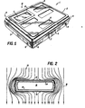
- Figure 1 is a perspective view of a preferred embodiment of a portable work station for transporting and/or storing electrically sensitive repair or replacement parts to an on-site field location without subjecting the stored parts to the potentially harmful effects of external electrical forces (fields). It can be seen that the portable work station comprises an electrically conductive container 1, preferably formed by blow molding.
- the container is manufactured from a blend of (1) any of the conventional thermoplastic materials which have heretofore been utilized in prior art blow molding processes and (2) particles of an electrically conductive material.
- any material which may assume a thermoplastic state can be utilized as the thermoplastic material incorporated within the blend.
- Such materials are generally blow molded in the temperature range of 250°-600°F (121-312°C).
- Polyethylene is a preferred material.
- Other exemplary materials are high-density polyethylene, polypropylene, polyvinyl chloride and elastomeric polyolefins. These materials are generally known not to be electrically conductive. Accordingly, particles of an electrically conductive material must be blended.therewith to render the composition of the final enclosure electrically conductive.
- Exemplary of such an electrically conductive material is carbon black particles.
- other electrically conductive materials such as, for example, aluminum particles may be utilized.
- Most metal filings are suitable but weight considerations dictate a preference toward lighter particles or filings.
- a particularly preferred blend of the materials is from 75-85 percent, by weight, of the thermoplastic material and from 15-25 percent, by weight, of the carbon black particles.
- An especially preferred blend is approximately 83 percent, by weight, of the thermoplastic material and approximately 17 percent, by weight, of the carbon black particles.
- the most preferred enclosure composition is from 75-85, preferable 83, percent, by weight, of polyethylene blended with from 15-25, preferably 17 percent, by weight, of carbon black particles.
- additives which serve to enhance the processability of the composition may be included as is well known to those in the art.
- An example of such additives are mold release additives.
- the two materials are blended, heated to extrusion temperature, extruded as a parison and blow molded into the desired shape.
- Figure 1 shows a portable work station or container 1 comprising a top enclosure means 2 and a bottom enclosure means 3 connected by flexible hinge means 4 (see Figures 5 and 7). Upon closing of container 1 the top enclosure means 2 and bottom enclosure means 3 are brought into close intimate contact and are interfaced along parting line 5.
- Container 1 may also contain a flexible latching means 6, preferably a latch gripping tab or extension 7, for releasably securing top enclosure means 2 to bottom enclosure means 3.
- container 1 may also be provided with label areas 8 shaped and sized so as to match up with adhesively applied labels (not shown).
- label areas 8 shaped and sized so as to match up with adhesively applied labels (not shown).
- one or more of the areas 8 are slightly recessed or sunken.
- logos or other trade indicia may be included within the areas 8, for example by recessing the area and raising the logo above the recessed surface.
- Container 1 also includes an electrical charge bleed-off or grounding means 9 on either enclosure means 2 or 3, but preferably on bottom enclosure means 3 and more preferably conductively attached thereto by way of a well-known male-female arrangement.
- Bleed-off means 9 is also formed from an electrically conductive material such as, for example, any electrically conductive metal (e.g. copper, aluminum etc.) and may take the form of a snap juncture or, alternatively, it may merely assume a pole or rod-like configuration to which clipping means such as, for example, an alligator clip may be attached.
- the container or work station 1 comprises a window means 10 comprising a sheet of optically transparent material 11 incorporated within, for example, the top enclosure means 2 by an electrically conducting frame-like retaining and engaging means 12 manufactured from a composition such as one of those described above with regard to means 2 and 3, and preferably of the same composition as means 2 and 3.
- Figure 5 is a top plan view of the electrically conductive container of Figure 1 wherein the optically transparent sheet 11 and the frame-like sheet engaging and retaining means 12 have been removed to reveal the presence of orifice 23 in container top enclosure means 2.
- Orifice 23 is peripherally surrounded by window means recess area 22.
- a group of holes 17 located in the recessed window area 22 serves to receive and to retainingly engage the legs 19 of sheet-engaging and retaining means 12. Accordingly, to ensure firm engagement of legs 19 in holes 17, the diameter of holes 17 should be equal to or slightly less than the diameter of legs 19. Alternatively, the legs 19 could be longer than the depth of holes 17 and have enlarged ends to snappingly engage holes 17. However, a sufficient number of holes 17 and associated cooperating legs 19 should be provided so that engaging and retaining means 12 can trappingly retain sheet 11 between means 12 and window means recess 22.
- Figure 8 which is a top plan view of means 12, shows the preferred frame-like configuration of means 12 which surrounds opening 18.
- which window means recess 22 of top enclosure means 2 includes a window stop recess 34 which accommodates a window stop 32 of the sheet-retaining and -engaging means 12.
- the window stop 32 of the sheet-retaining and -engaging means 12, and the inclusion of a window stop recess 34 to the window means recess 22 of top enclosure means 2 substantially eliminate lateral movement of window sheet 11 along the window recess area 22 of top enclosure means 2, thereby reducing the possibility of dust or other foreign matter entering the container 1.
- Reduction of lateral movement of window sheet 11 also reduces the possibility of a discontinuity in the electrically conductive surface of container 1. Additionally, the force with which window sheet 11 is engaged and retained within window-retaining indent 20 on recess means 22 of top enclosure 2 by the means 12 becomes much less critical.
- optically transparent materials generally utilized for window sheets or panes for example, polycarbonates and glass, are not electrically conductive and must be coated with an electrically conductive coating to render the entire surface of the container electrically conductive, electrically conductive communicative contact between the electrically conductive coating and the remainder of the electrically conductive enclosure is ensured by the present configuration.
- An electrically conductive coating onto a nonconducting surface may, for example, be provided by cathode sputtering, for example with an indium tin oxide.
- cathode sputtering for example with an indium tin oxide.
- Other methods of coating are possible, as disclosed in U.S. patents 4,369,208; 4,303,554; and 4,268,539.
- the container preferably includes an internal pad, preferably a foam anti-static pad, made of an electrically conductive material to reduce or eliminate the generation and accumulation of internal static electricity.
- An internal pad preferably a foam anti-static pad, made of an electrically conductive material to reduce or eliminate the generation and accumulation of internal static electricity.
- a preferred material for the pad is known in the art as "pink poly". This material is a polyethylene which has been impregnated with an organic liquid which acts as a hydroscopic "wetting agent" which attracts and holds moisture onto the surface of the pad to render the pad electrically conductive.
- U.S. patent 3,355,313 and Canadian Patent No. 810,595 disclose exemplary wetting agents.
- the pad could be formed from an electrically conductive loaded plastic foam such as a carbon-or aluminum-loaded polyurethane foam.
- This material is available in commercial volumes and is electrically conductive throughout,as opposed to merely having an electrically conductive surface coating.
- Yet another type of conductive pad is a polyethylene foam which has been sprayed with a conductive carbon or similar conductive solution to effect a conductive layer on the surface of the material.
- the internal pad may be preformed to the configuration of the electrically sensitive devices which may then be securely held thereby. Additionally, the pad is shaped and inserted into the container so as to be in electrically conductive communication with the electrically conductive enclosure means of the container. 'As a result of the conductivity of the internal pad and its electrically conductive communication with the container, any static charge which might be generated by frictional movement or other slight vibrations of the electrically sensitive device against the pad will immediately be conducted to, and (if the container is not grounded) reside on, the external surface of the container. Moreover, it is believed that the presence of a moist surface on the pad reduces the generation of friction and the accompanying static forces.
- Another possible and also known method for rendering plastic materials, both foamed and non-foamed, anti-static is the dispersal of an anti-static agent throughout the plastic. Initially, since continuity of the agent throughout the plastic is lacking, the anti-static properties are not good. However, in time, the agent migrates to the surface of the material much like the phenomenon known as migration (sweating) of incompatible plasticizers. Thus, after a period of time, a good conductive anti-static coating is formed.
- a recommended compound of this sort is: stearamidopropyldimethyl-2-hydroxyethylammonium nitrate, a cationic surface-active agent having the following structure:
- charge bleed-off means 9 is to afford a means for the easy attachment of one end of an electrically conductive wire whose other end carries a similar attachment means for electrically conductive communication with the machine or other device which is to be repaired in the field. Accordingly, any differential of electrical charge which may exist between the container and the machine will be equalized upon attachment of the wire. Thus, if the repair technician maintains physical/ electrically conductive communicative contact with the machine to be repaired, (i.e. grounds himself with respect to the machine), the electrically sensitive device will not be subjected to the adverse effects of uncontrolled electrical flow or discharge upon being incorporated within the machine being repaired.
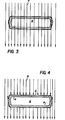
- Figure 3 schematically demonstrates the penetration of the interior 16 of a prior art electrically non-conductive container by an external electromagnetic or electrostatic field.
- Figures 2 and 4 schematically illustrate the shielding effect which the present conductive case affords to its interior 16 and to any devices contained therein when the container is placed in an electromagnetic field ( Figure 2) or an electrostatic field ( Figure 4).
- Double-wall construction shown in Figures 2 and 4 is preferred as affording a greater degree of physical protection to the contents.
- Both single and double wall blow molding are well known to those of skill in the art, and either type may be used.
- An additional significant function which the present conductive container performs is the bleeding-off of any internally generated static electrical charge from the electrically sensitive device to the surface of the container.
- the charge bled off by means 9 may come from a source of electrical charge in the vicinity of the electrically sensitive device, or may have been built up on the surface of the portable work station as a result of transportation of the work station (e.g. static from the repair technician walking).
Landscapes
- Engineering & Computer Science (AREA)
- Microelectronics & Electronic Packaging (AREA)
- Packaging Frangible Articles (AREA)
- Packaging Of Annular Or Rod-Shaped Articles, Wearing Apparel, Cassettes, Or The Like (AREA)
- Buffer Packaging (AREA)
- Details Of Rigid Or Semi-Rigid Containers (AREA)
- Elimination Of Static Electricity (AREA)
- Packages (AREA)
- Feeding Of Articles By Means Other Than Belts Or Rollers (AREA)
Applications Claiming Priority (2)
| Application Number | Priority Date | Filing Date | Title |
|---|---|---|---|
| US65929284A | 1984-10-10 | 1984-10-10 | |
| US659292 | 1984-10-10 |
Publications (3)
| Publication Number | Publication Date |
|---|---|
| EP0178038A2 true EP0178038A2 (de) | 1986-04-16 |
| EP0178038A3 EP0178038A3 (en) | 1986-06-25 |
| EP0178038B1 EP0178038B1 (de) | 1988-11-30 |
Family
ID=24644842
Family Applications (1)
| Application Number | Title | Priority Date | Filing Date |
|---|---|---|---|
| EP19850304003 Expired EP0178038B1 (de) | 1984-10-10 | 1985-06-05 | Antistatische elektrisch leitende Station |
Country Status (8)
| Country | Link |
|---|---|
| EP (1) | EP0178038B1 (de) |
| JP (1) | JPH0659912B2 (de) |
| BR (1) | BR8502506A (de) |
| CA (1) | CA1256485A (de) |
| DE (1) | DE3566602D1 (de) |
| ES (1) | ES295756Y (de) |
| MX (1) | MX157711A (de) |
| SG (1) | SG890G (de) |
Cited By (2)
| Publication number | Priority date | Publication date | Assignee | Title |
|---|---|---|---|---|
| EP0366537A1 (de) * | 1988-10-28 | 1990-05-02 | Thomson-Csf | Verfahren zur Herstellung einer Abschirmung, durch dieses Verfahren erhaltene Abschirmung und elektronische Anlage mit dieser Abschirmung |
| EP0310233A3 (de) * | 1987-08-12 | 1991-04-24 | International Control Automation Finance S.A. | Verbrennungsregelsystem |
Families Citing this family (2)
| Publication number | Priority date | Publication date | Assignee | Title |
|---|---|---|---|---|
| JPH0620911B2 (ja) * | 1986-12-27 | 1994-03-23 | 日本鉱業株式会社 | 半導体ウェーハー包装容器 |
| DE3907486A1 (de) * | 1989-03-08 | 1990-09-13 | Karl Otto Platz | Frontplatteneinsatz |
Family Cites Families (3)
| Publication number | Priority date | Publication date | Assignee | Title |
|---|---|---|---|---|
| US3801418A (en) * | 1972-03-16 | 1974-04-02 | Atomic Energy Commission | Transparent anti-static device |
| US4154344A (en) * | 1976-11-09 | 1979-05-15 | Minnesota Mining And Manufacturing Company | Material for forming envelopes used to protect electronic components |
| US4494651A (en) * | 1983-04-19 | 1985-01-22 | W. R. Grace & Co., Cryovac Div. | Electrically conductive anti-static work station |
-
1985
- 1985-05-06 MX MX20522085A patent/MX157711A/es unknown
- 1985-05-08 CA CA000481025A patent/CA1256485A/en not_active Expired
- 1985-05-27 BR BR8502506A patent/BR8502506A/pt unknown
- 1985-06-05 EP EP19850304003 patent/EP0178038B1/de not_active Expired
- 1985-06-05 DE DE8585304003T patent/DE3566602D1/de not_active Expired
- 1985-06-14 ES ES1985295756U patent/ES295756Y/es not_active Expired
- 1985-06-26 JP JP60138048A patent/JPH0659912B2/ja not_active Expired - Lifetime
-
1990
- 1990-01-04 SG SG890A patent/SG890G/en unknown
Cited By (4)
| Publication number | Priority date | Publication date | Assignee | Title |
|---|---|---|---|---|
| EP0310233A3 (de) * | 1987-08-12 | 1991-04-24 | International Control Automation Finance S.A. | Verbrennungsregelsystem |
| EP0559241A3 (en) * | 1987-08-12 | 1994-08-24 | Int Control Automation Finance | Housings for control systems |
| EP0366537A1 (de) * | 1988-10-28 | 1990-05-02 | Thomson-Csf | Verfahren zur Herstellung einer Abschirmung, durch dieses Verfahren erhaltene Abschirmung und elektronische Anlage mit dieser Abschirmung |
| FR2638596A1 (fr) * | 1988-10-28 | 1990-05-04 | Thomson Csf | Procede de realisation d'un blindage, blindage obtenu par ce procede et materiel electronique comportant ce blindage |
Also Published As
| Publication number | Publication date |
|---|---|
| JPH0659912B2 (ja) | 1994-08-10 |
| EP0178038B1 (de) | 1988-11-30 |
| EP0178038A3 (en) | 1986-06-25 |
| SG890G (en) | 1990-07-13 |
| BR8502506A (pt) | 1986-12-23 |
| DE3566602D1 (en) | 1989-01-05 |
| ES295756U (es) | 1987-07-01 |
| CA1256485A (en) | 1989-06-27 |
| JPS6193075A (ja) | 1986-05-12 |
| ES295756Y (es) | 1988-01-01 |
| MX157711A (es) | 1988-12-09 |
Similar Documents
| Publication | Publication Date | Title |
|---|---|---|
| US4494651A (en) | Electrically conductive anti-static work station | |
| US4327832A (en) | Container for packaging semiconductor components | |
| CA1196372A (en) | Anti-static transit case | |
| US9101750B2 (en) | Carrier assembly with caps for medical connectors | |
| IE831989L (en) | Container for electronic components | |
| EP0178038B1 (de) | Antistatische elektrisch leitende Station | |
| US5041319A (en) | Static protective laminated material | |
| US4722025A (en) | Ground latch and case | |
| EP2537780A1 (de) | Substratspeicherbehälter | |
| US7316325B2 (en) | Substrate container | |
| GB8333249D0 (en) | Electrically insulating articles | |
| EP0223615A3 (en) | Electrically conductive composite material | |
| US4463851A (en) | Protective enclosure for electronic devices | |
| US5232091A (en) | Semiconductor device shipping container | |
| EP0189240B1 (de) | Spleissgehäuse | |
| US5368500A (en) | Closure for electric plug | |
| KR100798533B1 (ko) | 기판 반송용 발포 박스 | |
| US4817263A (en) | Method of storing electrostatic discharge sensitive devices | |
| US5518120A (en) | Anti-static package for protecting sensitive electronic components from electrostatic charges | |
| JP3366502B2 (ja) | 基板用カセット | |
| DE102014005520B4 (de) | Laserverpackung | |
| EP1439616A1 (de) | Gegen statische ladung geschütztes gehäuse | |
| GB2119755A (en) | Protective enclosure for electronic devices | |
| ES2100648T3 (es) | Perfeccionamientos en los elementos de cajetines de conectores electricos. | |
| US5150786A (en) | Thermoplastic tubular container for semiconductor devices with longitudinal opening means |
Legal Events
| Date | Code | Title | Description |
|---|---|---|---|
| PUAI | Public reference made under article 153(3) epc to a published international application that has entered the european phase |
Free format text: ORIGINAL CODE: 0009012 |
|
| AK | Designated contracting states |
Kind code of ref document: A2 Designated state(s): BE DE FR GB IT NL |
|
| PUAL | Search report despatched |
Free format text: ORIGINAL CODE: 0009013 |
|
| AK | Designated contracting states |
Kind code of ref document: A3 Designated state(s): BE DE FR GB IT NL |
|
| 17P | Request for examination filed |
Effective date: 19860604 |
|
| 17Q | First examination report despatched |
Effective date: 19870923 |
|
| GRAA | (expected) grant |
Free format text: ORIGINAL CODE: 0009210 |
|
| AK | Designated contracting states |
Kind code of ref document: B1 Designated state(s): BE DE FR GB IT NL |
|
| REF | Corresponds to: |
Ref document number: 3566602 Country of ref document: DE Date of ref document: 19890105 |
|
| ITF | It: translation for a ep patent filed | ||
| ET | Fr: translation filed | ||
| RAP2 | Party data changed (patent owner data changed or rights of a patent transferred) |
Owner name: W.R. GRACE & CO.-CONN. (A CONNECTICUT CORP.) |
|
| NLT1 | Nl: modifications of names registered in virtue of documents presented to the patent office pursuant to art. 16 a, paragraph 1 |
Owner name: W.R. GRACE & CO.-CONN. TE NEW YORK, NEW YORK, VER. |
|
| PLBE | No opposition filed within time limit |
Free format text: ORIGINAL CODE: 0009261 |
|
| STAA | Information on the status of an ep patent application or granted ep patent |
Free format text: STATUS: NO OPPOSITION FILED WITHIN TIME LIMIT |
|
| REG | Reference to a national code |
Ref country code: GB Ref legal event code: 732 |
|
| 26N | No opposition filed | ||
| BECA | Be: change of holder's address |
Free format text: 881130 W.R. *GRACE & CO.-CONN.:GRACE PLAZA 1114 AVENUE, OF THE AMERICAS NEW YORK NEW YORK 10036 |
|
| BECN | Be: change of holder's name |
Effective date: 19881220 |
|
| REG | Reference to a national code |
Ref country code: FR Ref legal event code: CD |
|
| ITTA | It: last paid annual fee | ||
| PGFP | Annual fee paid to national office [announced via postgrant information from national office to epo] |
Ref country code: GB Payment date: 19940526 Year of fee payment: 10 |
|
| PGFP | Annual fee paid to national office [announced via postgrant information from national office to epo] |
Ref country code: DE Payment date: 19940608 Year of fee payment: 10 |
|
| PGFP | Annual fee paid to national office [announced via postgrant information from national office to epo] |
Ref country code: FR Payment date: 19940609 Year of fee payment: 10 |
|
| PGFP | Annual fee paid to national office [announced via postgrant information from national office to epo] |
Ref country code: NL Payment date: 19940630 Year of fee payment: 10 |
|
| PGFP | Annual fee paid to national office [announced via postgrant information from national office to epo] |
Ref country code: BE Payment date: 19940808 Year of fee payment: 10 |
|
| PG25 | Lapsed in a contracting state [announced via postgrant information from national office to epo] |
Ref country code: GB Effective date: 19950605 |
|
| PG25 | Lapsed in a contracting state [announced via postgrant information from national office to epo] |
Ref country code: BE Effective date: 19950630 |
|
| BERE | Be: lapsed |
Owner name: W.R. GRACE & CO.-CONN. Effective date: 19950630 |
|
| PG25 | Lapsed in a contracting state [announced via postgrant information from national office to epo] |
Ref country code: NL Effective date: 19960101 |
|
| GBPC | Gb: european patent ceased through non-payment of renewal fee |
Effective date: 19950605 |
|
| PG25 | Lapsed in a contracting state [announced via postgrant information from national office to epo] |
Ref country code: FR Effective date: 19960229 |
|
| NLV4 | Nl: lapsed or anulled due to non-payment of the annual fee |
Effective date: 19960101 |
|
| PG25 | Lapsed in a contracting state [announced via postgrant information from national office to epo] |
Ref country code: DE Effective date: 19960301 |
|
| REG | Reference to a national code |
Ref country code: FR Ref legal event code: ST |