EP0178095A2 - Verfahren zur Tintenaufbereitung für einen Tintenstrahldrucker - Google Patents
Verfahren zur Tintenaufbereitung für einen Tintenstrahldrucker Download PDFInfo
- Publication number
- EP0178095A2 EP0178095A2 EP85306835A EP85306835A EP0178095A2 EP 0178095 A2 EP0178095 A2 EP 0178095A2 EP 85306835 A EP85306835 A EP 85306835A EP 85306835 A EP85306835 A EP 85306835A EP 0178095 A2 EP0178095 A2 EP 0178095A2
- Authority
- EP
- European Patent Office
- Prior art keywords
- ink
- dye
- solvent
- sonic vibration
- process according
- Prior art date
- Legal status (The legal status is an assumption and is not a legal conclusion. Google has not performed a legal analysis and makes no representation as to the accuracy of the status listed.)
- Granted
Links
Images

Classifications
-
- C—CHEMISTRY; METALLURGY
- C09—DYES; PAINTS; POLISHES; NATURAL RESINS; ADHESIVES; COMPOSITIONS NOT OTHERWISE PROVIDED FOR; APPLICATIONS OF MATERIALS NOT OTHERWISE PROVIDED FOR
- C09D—COATING COMPOSITIONS, e.g. PAINTS, VARNISHES OR LACQUERS; FILLING PASTES; CHEMICAL PAINT OR INK REMOVERS; INKS; CORRECTING FLUIDS; WOODSTAINS; PASTES OR SOLIDS FOR COLOURING OR PRINTING; USE OF MATERIALS THEREFOR
- C09D11/00—Inks
- C09D11/30—Inkjet printing inks
-
- B—PERFORMING OPERATIONS; TRANSPORTING
- B41—PRINTING; LINING MACHINES; TYPEWRITERS; STAMPS
- B41J—TYPEWRITERS; SELECTIVE PRINTING MECHANISMS, i.e. MECHANISMS PRINTING OTHERWISE THAN FROM A FORME; CORRECTION OF TYPOGRAPHICAL ERRORS
- B41J2/00—Typewriters or selective printing mechanisms characterised by the printing or marking process for which they are designed
- B41J2/005—Typewriters or selective printing mechanisms characterised by the printing or marking process for which they are designed characterised by bringing liquid or particles selectively into contact with a printing material
- B41J2/01—Ink jet
- B41J2/17—Ink jet characterised by ink handling
- B41J2/195—Ink jet characterised by ink handling for monitoring ink quality
-
- C—CHEMISTRY; METALLURGY
- C09—DYES; PAINTS; POLISHES; NATURAL RESINS; ADHESIVES; COMPOSITIONS NOT OTHERWISE PROVIDED FOR; APPLICATIONS OF MATERIALS NOT OTHERWISE PROVIDED FOR
- C09D—COATING COMPOSITIONS, e.g. PAINTS, VARNISHES OR LACQUERS; FILLING PASTES; CHEMICAL PAINT OR INK REMOVERS; INKS; CORRECTING FLUIDS; WOODSTAINS; PASTES OR SOLIDS FOR COLOURING OR PRINTING; USE OF MATERIALS THEREFOR
- C09D11/00—Inks
Definitions
- the present invention relates to a process for the preparation of an ink for an ink jet printer. More particularly, the present invention relates to a process for the preparation of an ink which can be stably injected in a so-called drop-on-demand type ink jet printer which performs recording, e.g., by injecting ink particles by an action of a piezo-electric element, or of bubbles formed by heating.
- ink particles are injected from a pressure chamber through a nozzle to a recording paper in accordance with an electric signal corresponding to information to be recorded.
- the recording head is driven by the action of a piezo-electric element provided at the pressure chamber, or by the action ot a pressure of bubbles tormed by heating a part of an ink in the pressure chamber (so-called bubble jet type).
- the inventors discovered that even if the dissolved gas remaining in the ink is removed by a reduction of the pressure or by heating, a stable injection could not be pertormed when a smaller size recording head was used. Nevertheless, it is thought that, to increase the recording speed, the size of the recording head must be reduced.
- an ink jet printer provided with a super sonic vibration applying device is described.
- this device is still directed to remove, from an ink, gas bubbles dissolved in the ink during storage thereof or atter the initial removal of gas bubbles by heating the ink or a reduction of the pressure therein. Therefore, a super sonic vibration applying device must be provided within an ink jet printer. Further, provision of a super sonic vibration applying device to an ink jet printer has disadvantages in that the construction of the printer becomes complicated and heating of the ink occurs.
- a process for preparing an ink before its introduction into a drop-on-demand type-ink jet printer the ink comprising a dye and a solvent, in which sonic vibration is applied to remove a gas entrained in the ink by the incorporation of the dye in the formation of the ink.
- a process for preparing an ink before its introduction into a drop-on-demand type ink jet printer the ink being formed by the steps of dissolving a dye in a portion of a solvent and mixing the resultant system comprising the dye and the portion of the solvent with the remaining portion of the solvent to form a homogeneous ink comprising the dye and the solvent, in which sonic vibration is applied to remove a gas entrained in the ink by the incorporation of the dye in the course of the formation of the ink.
- An embodiment of the invention can provide a process for preparing an ink which can be stably injected in a drop-on-demand type ink jet printer.
- An embodiment of the invention can previously remove, from an ink for a drop-on-demand type ink jet printer, a gas which would otherwise form bubbles during a recording operation by the ink jet printer.
- a sonic vibration preferably of a frequency in the range 2 kHz to 55 kHz, and/or of an energy equal to or larger than the energy received by the ink at the recording head is applied in advance to the ink during the preparation process, to remove the bubbles.
- sonic energy applied to the ink during the preparation process may remove gas entrained in the ink by incorporation of the dye.
- the inventors discovered that a gas is entrained in an ink when a dye is incorporated in a solvent, and the gas thus entrained in the ink by the dye cannot be removed by a gas-removing treatment such as heating or a reduction of the pressure but can be removed by the application of sonic vibration.
- the intended effect can be attained irrespective of the time of the application of the sonic vibration. Even if sonic vibration is applied after the ink has been formed and stored for a while, the intended effect still can be attained. However, an especially good effect is attained when sonic vibration is applied at the time of incorporating the dye into the solvent and/or when the dye is incorporated into a small amount of the solvent while applying sonic vibration, and the remainder of the solvent then being added. Accordingly, adoption ot this method is preferred.
- sonic vibration may be applied preferably during the step of dissolving a dye in a portion of a solvent and/or after the step of mixing a system comprising a dye and a portion of a solvent with the remaining portion of the solvent.
- Other sequences of mixing a dye and a solvent may be used in the invention.
- two or more parts of a dye may be incorporated into two or more parts of a solvent, respectively, and the resultant two or more mixtures then mixed with each other and, optionally, with a further part of the solvent.
- a dye may be a mixture of dyes and a solvent may be a mixture of solvents.
- the inks in the present invention are ot the type prepared by dissolving a dye in a solvent.
- the kinds of dye and solvent and the composition of the ink are not particularly critical.
- typical dyes to be used in the present invention there can be mentioned C.I. Acid Red 92, C.I. Direct Red 227, C.I. Reactive Blue 71, C.I. Direct Yellow 50, C.I. Direct Black 19, C.I. Direct Blue 86, C.I. Acid Blue 112, C.I. Acid Red 131, C.I. Direct Yellow 86, and C.I. Reactive Yellow 81.
- Water is ordinarily used as the solvent, and in many cases, to improve ink characteristics such as the drying property and surtace tension, a water-soluble organic solvent such as ethylene glycol, diethylene glycol, propylene glycol or carbitol is incorporated.
- a water-soluble organic solvent such as ethylene glycol, diethylene glycol, propylene glycol or carbitol
- an organic solvent type ink may be used instead of the aqueous ink, and attainment of the intended effect of the present invention is not inhibited even if a surface active agent or an inorganic hygroscopic agent is incorporated in the ink (that is, the solvent).
- gas-removing treatment by a reduction of the pressure or by heating is carried out in combination with the treatment of the invention.
- the thus prepared ink can be injected stably, or will not form bubbles in a recording head of a drop-on-demand type ink jet printer, even if a small size pressure chamber is used in the recording head to increase the recording speed.
- an ink to which reduction of the pressure at 15 torr for 15 hours is applied can be continuously injected for 1 to 2 minutes; an ink to which heating at 100°C for 3 hours is applied can be continuously injected for 1 to 2 minutes; and an ink to which sonic vibration is applied can be continuously injected for more than 2 hours when used soon after or more than 2 months after the application of sonic vibration.
- Figure 1 shows an example of a recording head of a drop-on-demand type ink jet printer, in which reference numeral 1 represents a base plate, reference numeral 2 represents a top plate (vibrating plate), reference numeral 3 designates a piezo-electric element, reference numeral 4 designates a pressure chamber, reference numeral 5 represents an ink supply tube, and reference numeral 6 designates a nozzle.
- An ink is filled in the pressure chamber 4 through the ink supply tube 5 trom an ink vessel (not shown), the piezo-electric element 3 is driven by an electric signal 7 corresponding to information to be recorded, and the top plate 2-is vibrated.-to compress the ink in the pressure chamber 4, whereby the ink in the pressure chamber 4 is injected in the form of ink drops 8 on to a recording paper (not shown) from the nozzle 6 to effect recording.
- a recording head a shown in Figs. 2A and 2B was fabricated by way of trial.
- reference numeral 11 represents a ceramic (alumina) base plate
- reference numeral 12 represents a glass sheet
- reference numeral 13 designates a piezo-electric element
- reference numeral 14 designates a pressure chamber
- reference numeral 15 represents an ink supply path
- reference numeral 16 designates a nozzle.
- the glass sheet 12 had a thickness of 0.3 mm
- the piezo-electric element 13 had a width of 1.4 mm and a length of 20 mm
- the pressure chamber 14 had a width of 1.45 mm and a depth of 0.1 mm.
- the injection tests were carried out by using the inks A through E which had been subjected to the gas-removing treatment by reduction of the pressure; ink B which had been subjected to the gas-removing treatment by heating; and inks A through C which had not been subjected to the gas-removing treatment, and the states in the head were observed.
- removal of the gas by the gas-removing treatment was confirmed by a dissolved-oxygen meter, and injection was carried out at an atomizing frequency of 1 kHz.
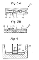
- a recording head b in which the size of the pressure chamber was reduced to increase the atomizing trequency and recording speed was fabricated by way of trial.
- This recording head b is shown in Fig. 3.
- Members corresponding to those of the recording head a are represented by the same reference numerals.
- Both the base plate 11 and top plate 12 were formed from stainless steel.
- the top plate 12 had a thickness of 0.2 mm
- the piezo-electric element 13 had a width of 1.4 mm and a length of 5 mm
- the pressure chamber 14 had a width of 1.6 mm and a depth of 0.05 mm.
- the ink B When the ink B was charged in the head b after bubbles had been thus formed, the ink B could be injected stably for a long time, although stable injection of the ink B ordinarily became impossible within 30 seconds as pointed out hereinbefore.
- the gas is composed mainly of nitrogen, oxygen, and carbon dioxide.
- this gas becomes present in the ink. That is, the state of the gas present in the ink has not been elucidated. Since the state of the formation of bubbles differs according to the kind of dye used, it is construed that the gas is present in the ink in the state where the gas is combined with the dye in some manner or other, and the combined gas is isolated from the dye by a change in the sonic pressure.
- the above components were mixed in a flask having a capacity of 500 ml and a solution was formed while transmitting sonic vibration therethrough by using an ultrasonic washing device (BRANSONIC 220).
- BRANSONIC 220 an ultrasonic washing device
- the solution was then mixed with the following components and filtered through a 3 ⁇ m-filter to form an ink.
- the above components were mixed in a tlask having a capacity of 300 ml and a solution was formed while transmitting sonic vibration therethrough by the ultrasonic washing device.
- the solution was then mixed with the following components and filtered through a 3 ⁇ m-filter to torm an ink.
- the above components were mixed in a flask having a capacity of 500 ml and a solution was formed while transmitting sonic vibration therethrough by using an ultrasonic washing device.
- the solution was then mixed with the following components, sonic vibration was again transmitted therethrough, and the solution was then filtered through a 3 um-filter to form an ink.
- the above components were mixed in a flask having a capacity of 500 ml and a solution was formed while transmitting sonic vibration therethrough by using the ultrasonic washing device.
- the solution was then mixed with the following components, sonic vibration was again transmitted therethrough, and the solution was then filtered through a 3 ⁇ m-fister to form an ink.
- the above components were mixed in a flask having a capacity of 500 ml and a solution was tormed while transmitting sonic vibration therethrough by using an ultrasonic washing device.
- the solution was then mixed with the following components, sonic vibration was again transmitted therethrough, and the solution was then tiltered through a 3 pm-tilter to form an ink.
- the above components were mixed in a flask having a capacity of 500 ml and a solution was formed while transmitting sonic vibration therethrough by using an ultrasonic washing device.
- the solution was mixed with the following components, sonic vibration was again transmitted therethrough, and the solution was then filtered through a 3 um-filter to form an ink.
- the above components were mixed in a flask having a capacity of 500 ml and a solution was formed while transmitting sonic vibration therethrough by using an ultrasonic washing device.
- the solution was mixed with the following components, sonic vibration was again transmitted therethrough, and the solution was then passed through a 3 um-tilter to form an ink.
- the above components were mixed in a flask having a capacity of 500 ml and a solution was formed while transmitting sonic vibration therethrough, by using an ultrasonic washing device. The solution was then filtered through a 3 um-filter to torm an ink.
- the injection test was carried out in the tollowing manner. Namely, after bubbles were removed by a reduction of the pressure, the ink was injected continuously for 30 minutes at an atomizing frequency ot 2 kHz and a particle speed of 3 m/sec by using the head b.
- the pulse duration was 30 ⁇ s and the pulse tall time was less than 1 ⁇ s. The obtained results are shown in Table 3.
- the above components were mixed in a flask and a solution was formed while transmitting sonic vibration therethrough by using an ultrasonic washing device.
- the solution was then mixed with 365 parts by weight of ethylene glycol and sonic vibration was again transmitted therethrough to torm an ink P A .
- the above components were mixed in a flask and a solution was formed while transmitting sonic vibration therethrough by using an ultrasonic washing device.
- the solution was then mixed with 365 parts by weight of ethylene glycol and sonic vibration was again transmitted therethrough to form an ink P B .
- Ink Q was prepared in a manner similar to that of the ink P except that ink Q was prepared without the application of sonic vibration during the procedure.
- ink P could be stably injected in all nozzles of the recording heads for more than 180 minutes.
- injection became unstable in all nozzlesof the heads soon after starting injection at 3 kHz, injection stopped in all nozzles of the heads within one minute, and bubbles could be seen in the ink which was ejected from the nozzles by purging. All of nozzles in which injection stopped could be recovered by purging.
- the injection stability is highly improved. More specitically, for example, when the inks B, F, H, and K having the same composition are compared, it is seen that although the injection stability is bad in the inks B and F through which sonic vibration was not transmitted, the injection stability is good in the inks H and K through which sonic vibration was transmitted during the preparation process. This difference is similarly observed among the inks D, G, and J.
- an ink through which sonic vibration is transmitted to effect the removal of bubbles has a good injection stability even at a higher atomizing frequency. This can be seen in the experiment using ink P at an atomizing frequency of 3 kHz.
- each of the inks J and K were independently charged in plastic vessels having a capacity of 1 liter, and the inks were allowed to stand in contact with the air for 2 months.
- Each ink was filled in the head b without removing the gas by a reduction of the pressure and was then injected. Injection could be performed as stably as in the case where the ink was injected before standing. From this fact, it is seen that the gas generated by sonic vibration has properties ditterent from those of the gas dissolved and left in the solvent and if this gas is once removed by the application of sonic vibration, the effect of the present invention remains.
- the above phenomenon is influenced by the shape of the head and the surface roughness of the ink path.
- the shape of the head For example, as pointed out hereinbefore, if a fin or the like is present on the wall surface of the ink path, bubbles are trapped by the fin or the like, and the injection stability is greatly influenced according to the shape of the pressure chamber. Accordingly, in designing and constructing the recording head, care should be taken that the generation of bubbles is controlled and the discharge of bubbles is promoted. Furthermore, in the ink, it is necessary that such a gas should be removed in advance.
- sonic vibration is applied to the ink which is being prepared or has been prepared so that a gas entrained into the ink by incorporation of a dye therein can be removed.
- This ink can be stably injected through a recording head, even if the size of the head is made smaller to increase the atomizing frequency, or the recording speed.
Landscapes
- Chemical & Material Sciences (AREA)
- Engineering & Computer Science (AREA)
- Life Sciences & Earth Sciences (AREA)
- Materials Engineering (AREA)
- Wood Science & Technology (AREA)
- Organic Chemistry (AREA)
- Quality & Reliability (AREA)
- Inks, Pencil-Leads, Or Crayons (AREA)
- Ink Jet (AREA)
- Ink Jet Recording Methods And Recording Media Thereof (AREA)
Applications Claiming Priority (2)
| Application Number | Priority Date | Filing Date | Title |
|---|---|---|---|
| JP202070/84 | 1984-09-28 | ||
| JP59202070A JPS6181471A (ja) | 1984-09-28 | 1984-09-28 | インクジエツトプリンタ用インクの製造方法 |
Publications (3)
| Publication Number | Publication Date |
|---|---|
| EP0178095A2 true EP0178095A2 (de) | 1986-04-16 |
| EP0178095A3 EP0178095A3 (en) | 1986-10-08 |
| EP0178095B1 EP0178095B1 (de) | 1989-08-09 |
Family
ID=16451448
Family Applications (1)
| Application Number | Title | Priority Date | Filing Date |
|---|---|---|---|
| EP85306835A Expired EP0178095B1 (de) | 1984-09-28 | 1985-09-26 | Verfahren zur Tintenaufbereitung für einen Tintenstrahldrucker |
Country Status (5)
| Country | Link |
|---|---|
| US (1) | US4948427A (de) |
| EP (1) | EP0178095B1 (de) |
| JP (1) | JPS6181471A (de) |
| KR (1) | KR870001880B1 (de) |
| DE (1) | DE3572139D1 (de) |
Cited By (1)
| Publication number | Priority date | Publication date | Assignee | Title |
|---|---|---|---|---|
| EP0618277A1 (de) * | 1993-03-30 | 1994-10-05 | Canon Kabushiki Kaisha | Tinte, Tintenstrahl-Aufzeichnungsverfahren unter Verwendung derselben, Werkzeug enthaltend diese Tinte und Verfahren zu ihrer Herstellung |
Families Citing this family (15)
| Publication number | Priority date | Publication date | Assignee | Title |
|---|---|---|---|---|
| JPH0726049B2 (ja) * | 1986-12-01 | 1995-03-22 | キヤノン株式会社 | インクジェット記録方法 |
| US5909231A (en) * | 1995-10-30 | 1999-06-01 | Hewlett-Packard Co. | Gas flush to eliminate residual bubbles |
| JP3846083B2 (ja) * | 1998-02-06 | 2006-11-15 | ブラザー工業株式会社 | インクジェット記録装置 |
| JP2004083621A (ja) * | 2002-08-22 | 2004-03-18 | Brother Ind Ltd | インクジェット記録用水性インク |
| US20040053803A1 (en) * | 2002-09-13 | 2004-03-18 | Kimberly-Clark Worldwide, Inc. | Method for enhancing cleansing vehicles and cleansing vehicles utilizing such method |
| US6726754B2 (en) | 2002-09-13 | 2004-04-27 | Kimberly-Clark Worldwide, Inc. | Method for enzyme mediated removal of gas from inks, and reduced gas inks |
| JP2005097348A (ja) * | 2003-09-22 | 2005-04-14 | Konica Minolta Holdings Inc | 分散系インクジェットインクの製造方法及びインクジェット記録方法 |
| JP4815747B2 (ja) * | 2004-03-16 | 2011-11-16 | コニカミノルタホールディングス株式会社 | 分散染料インクジェットインクの製造方法およびインクジェット記録方法 |
| JP2005263880A (ja) * | 2004-03-17 | 2005-09-29 | Konica Minolta Holdings Inc | インクジェットインク用水性分散液および分散系インクジェットインクの製造方法、インクジェット記録方法 |
| JP2005281523A (ja) * | 2004-03-30 | 2005-10-13 | Konica Minolta Holdings Inc | インクジェットインクの製造方法及びインクジェット記録方法 |
| US7476047B2 (en) * | 2004-04-30 | 2009-01-13 | Kimberly-Clark Worldwide, Inc. | Activatable cleaning products |
| US7604623B2 (en) * | 2005-08-30 | 2009-10-20 | Kimberly-Clark Worldwide, Inc. | Fluid applicator with a press activated pouch |
| US7575384B2 (en) * | 2005-08-31 | 2009-08-18 | Kimberly-Clark Worldwide, Inc. | Fluid applicator with a pull tab activated pouch |
| US7565987B2 (en) * | 2005-08-31 | 2009-07-28 | Kimberly-Clark Worldwide, Inc. | Pull tab activated sealed packet |
| TWI341260B (en) * | 2008-04-18 | 2011-05-01 | Ind Tech Res Inst | Supply system |
Family Cites Families (12)
| Publication number | Priority date | Publication date | Assignee | Title |
|---|---|---|---|---|
| US3904392A (en) * | 1973-03-16 | 1975-09-09 | Eastman Kodak Co | Method of and apparatus for debubbling liquids |
| JPS5120591A (ja) * | 1974-08-12 | 1976-02-18 | Nissan Motor | Shusekikairoyososhizairyono nendochoseiho |
| CA1095154A (en) * | 1976-08-10 | 1981-02-03 | James A. Van Vechten | Heterostructure semiconductor devices |
| JPS5418975A (en) * | 1977-07-14 | 1979-02-13 | Canon Kk | Printing method |
| JPS5517571A (en) * | 1978-07-26 | 1980-02-07 | Seiko Epson Corp | Ink injection device |
| JPS5584672A (en) * | 1978-12-20 | 1980-06-26 | Ricoh Co Ltd | Ink jet recorder |
| JPS5587569A (en) * | 1978-12-27 | 1980-07-02 | Ricoh Co Ltd | Ink jet recording device |
| FR2447646A1 (fr) * | 1979-01-29 | 1980-08-22 | Materiel Telephonique | Filtre numerique transversal pour traitement en temps partage sur plusieurs canaux |
| JPS5830149B2 (ja) * | 1979-03-27 | 1983-06-27 | 株式会社リコー | 気泡除去装置 |
| US4323908A (en) * | 1980-08-01 | 1982-04-06 | International Business Machines Corp. | Resonant purging of drop-on-demand ink jet print heads |
| US4383859A (en) * | 1981-05-18 | 1983-05-17 | International Business Machines Corporation | Ink jet inks and method of making |
| JPS5880354A (ja) * | 1981-11-09 | 1983-05-14 | Koji Niimura | 分散染料の安定分散液の製法 |
-
1984
- 1984-09-28 JP JP59202070A patent/JPS6181471A/ja active Granted
-
1985
- 1985-09-26 EP EP85306835A patent/EP0178095B1/de not_active Expired
- 1985-09-26 DE DE8585306835T patent/DE3572139D1/de not_active Expired
- 1985-09-26 KR KR1019850007092A patent/KR870001880B1/ko not_active Expired
-
1989
- 1989-05-30 US US07/358,459 patent/US4948427A/en not_active Expired - Lifetime
Cited By (2)
| Publication number | Priority date | Publication date | Assignee | Title |
|---|---|---|---|---|
| EP0618277A1 (de) * | 1993-03-30 | 1994-10-05 | Canon Kabushiki Kaisha | Tinte, Tintenstrahl-Aufzeichnungsverfahren unter Verwendung derselben, Werkzeug enthaltend diese Tinte und Verfahren zu ihrer Herstellung |
| US5447562A (en) * | 1993-03-30 | 1995-09-05 | Canon Kabushiki Kaisha | Ink, ink-jet recording method making use of the ink, instrument provided with the ink and production method of the ink |
Also Published As
| Publication number | Publication date |
|---|---|
| EP0178095A3 (en) | 1986-10-08 |
| JPH0159309B2 (de) | 1989-12-15 |
| JPS6181471A (ja) | 1986-04-25 |
| KR860002668A (ko) | 1986-04-28 |
| US4948427A (en) | 1990-08-14 |
| DE3572139D1 (en) | 1989-09-14 |
| KR870001880B1 (ko) | 1987-10-20 |
| EP0178095B1 (de) | 1989-08-09 |
Similar Documents
| Publication | Publication Date | Title |
|---|---|---|
| EP0178095B1 (de) | Verfahren zur Tintenaufbereitung für einen Tintenstrahldrucker | |
| US5160370A (en) | Recording liquid and ink-jet recording method making recording unit, ink cartridge, and ink-jet recording apparatus making use thereof | |
| CA1084653A (en) | Ink composition for ink jet printing | |
| US5229786A (en) | Ink-jet recording method, recording unit, ink cartridge and recording apparatus employing recording liquid | |
| JP3466800B2 (ja) | インクジェット用インク、インクジェット記録方法及びインクジェット機器 | |
| US4489334A (en) | Immersible oxygen absorbing capsule for ink jet fluid supply | |
| TW512097B (en) | Ink, image recording process, ink cartridge, recording unit, ink set, crust-preventing method and image forming apparatus | |
| EP0224172B2 (de) | Aufzeichnungsflüssigkeit und Aufzeichnungsverfahren unter Verwendung derselben | |
| US5790157A (en) | Ink filling method and apparatus for ink cartridge | |
| US6585362B2 (en) | Ink composition, ink cartridge having ink composition, and method of filling ink cartridge | |
| EP0624470B1 (de) | Tintenstrahlaufzeichnungsverfahren und -Gerät | |
| JPH04211470A (ja) | インク、これを用いたインクジェット記録方法及び機器 | |
| JPS62191033A (ja) | 均一液滴の形成方法 | |
| JPH0692551B2 (ja) | ドロップ・オン・デマンド型インク・ジェット印刷用のインク組成物 | |
| JPS58217567A (ja) | インクジエツト記録用インク組成物およびインクジエツト記録方法 | |
| JP2003503830A (ja) | 化学的膜洗浄及び乾燥 | |
| KR100206036B1 (ko) | 잉크보유재료 그의 제조방법, 잉크분사기록장치 및 잉크분사기록방법 | |
| EP0933405B1 (de) | Wässrige Tintenzusammensetzung, Verfahren zur Herstellung und Aufzeichnung mittels dieses Tintenstrahls | |
| JPH0889911A (ja) | 洗浄方法 | |
| US5824142A (en) | Ink composition, process for its preparation, and ink-jet recording process | |
| JP2000094707A (ja) | インクジェットヘッド及び該インクジェットヘッドへのインク導入方法及び導入液 | |
| JPH0671885A (ja) | インクジェット記録ヘッド、その製造方法、及び記録装置 | |
| JPH0693218A (ja) | インク、これを用いたインクジェット記録方法及び係るインクを用いたインクジェット記録用機器 | |
| US7188926B2 (en) | Filler solution for inkjet head, inkjet head, and recording apparatus | |
| JP2002285053A (ja) | インク及び該インクを用いるインクジェット記録装置 |
Legal Events
| Date | Code | Title | Description |
|---|---|---|---|
| PUAI | Public reference made under article 153(3) epc to a published international application that has entered the european phase |
Free format text: ORIGINAL CODE: 0009012 |
|
| AK | Designated contracting states |
Kind code of ref document: A2 Designated state(s): DE FR GB IT SE |
|
| PUAL | Search report despatched |
Free format text: ORIGINAL CODE: 0009013 |
|
| AK | Designated contracting states |
Kind code of ref document: A3 Designated state(s): DE FR GB IT SE |
|
| 17P | Request for examination filed |
Effective date: 19861217 |
|
| 17Q | First examination report despatched |
Effective date: 19880311 |
|
| GRAA | (expected) grant |
Free format text: ORIGINAL CODE: 0009210 |
|
| AK | Designated contracting states |
Kind code of ref document: B1 Designated state(s): DE FR GB IT SE |
|
| REF | Corresponds to: |
Ref document number: 3572139 Country of ref document: DE Date of ref document: 19890914 |
|
| ET | Fr: translation filed | ||
| ITF | It: translation for a ep patent filed | ||
| PLBE | No opposition filed within time limit |
Free format text: ORIGINAL CODE: 0009261 |
|
| STAA | Information on the status of an ep patent application or granted ep patent |
Free format text: STATUS: NO OPPOSITION FILED WITHIN TIME LIMIT |
|
| 26N | No opposition filed | ||
| ITTA | It: last paid annual fee | ||
| PGFP | Annual fee paid to national office [announced via postgrant information from national office to epo] |
Ref country code: FR Payment date: 19940909 Year of fee payment: 10 |
|
| PGFP | Annual fee paid to national office [announced via postgrant information from national office to epo] |
Ref country code: SE Payment date: 19940915 Year of fee payment: 10 |
|
| EAL | Se: european patent in force in sweden |
Ref document number: 85306835.1 |
|
| PG25 | Lapsed in a contracting state [announced via postgrant information from national office to epo] |
Ref country code: SE Effective date: 19950927 |
|
| PG25 | Lapsed in a contracting state [announced via postgrant information from national office to epo] |
Ref country code: FR Effective date: 19960531 |
|
| EUG | Se: european patent has lapsed |
Ref document number: 85306835.1 |
|
| REG | Reference to a national code |
Ref country code: FR Ref legal event code: ST |
|
| REG | Reference to a national code |
Ref country code: GB Ref legal event code: IF02 |
|
| PGFP | Annual fee paid to national office [announced via postgrant information from national office to epo] |
Ref country code: GB Payment date: 20040922 Year of fee payment: 20 |
|
| PGFP | Annual fee paid to national office [announced via postgrant information from national office to epo] |
Ref country code: DE Payment date: 20040923 Year of fee payment: 20 |
|
| PG25 | Lapsed in a contracting state [announced via postgrant information from national office to epo] |
Ref country code: GB Free format text: LAPSE BECAUSE OF EXPIRATION OF PROTECTION Effective date: 20050925 |
|
| REG | Reference to a national code |
Ref country code: GB Ref legal event code: PE20 |