EP0178781A2 - Steueranlage für eine elektromagnetische Kraftfahrzeugkupplung - Google Patents
Steueranlage für eine elektromagnetische Kraftfahrzeugkupplung Download PDFInfo
- Publication number
- EP0178781A2 EP0178781A2 EP85306484A EP85306484A EP0178781A2 EP 0178781 A2 EP0178781 A2 EP 0178781A2 EP 85306484 A EP85306484 A EP 85306484A EP 85306484 A EP85306484 A EP 85306484A EP 0178781 A2 EP0178781 A2 EP 0178781A2
- Authority
- EP
- European Patent Office
- Prior art keywords
- clutch
- engine speed
- signal
- engine
- selector lever
- Prior art date
- Legal status (The legal status is an assumption and is not a legal conclusion. Google has not performed a legal analysis and makes no representation as to the accuracy of the status listed.)
- Granted
Links
Images


Classifications
-
- F—MECHANICAL ENGINEERING; LIGHTING; HEATING; WEAPONS; BLASTING
- F16—ENGINEERING ELEMENTS AND UNITS; GENERAL MEASURES FOR PRODUCING AND MAINTAINING EFFECTIVE FUNCTIONING OF MACHINES OR INSTALLATIONS; THERMAL INSULATION IN GENERAL
- F16D—COUPLINGS FOR TRANSMITTING ROTATION; CLUTCHES; BRAKES
- F16D48/00—External control of clutches
- F16D48/06—Control by electric or electronic means, e.g. of fluid pressure
- F16D48/068—Control by electric or electronic means, e.g. of fluid pressure using signals from a manually actuated gearshift linkage
-
- F—MECHANICAL ENGINEERING; LIGHTING; HEATING; WEAPONS; BLASTING
- F16—ENGINEERING ELEMENTS AND UNITS; GENERAL MEASURES FOR PRODUCING AND MAINTAINING EFFECTIVE FUNCTIONING OF MACHINES OR INSTALLATIONS; THERMAL INSULATION IN GENERAL
- F16D—COUPLINGS FOR TRANSMITTING ROTATION; CLUTCHES; BRAKES
- F16D37/00—Clutches in which the drive is transmitted through a medium consisting of small particles, e.g. centrifugally speed-responsive
- F16D37/02—Clutches in which the drive is transmitted through a medium consisting of small particles, e.g. centrifugally speed-responsive the particles being magnetisable
-
- F—MECHANICAL ENGINEERING; LIGHTING; HEATING; WEAPONS; BLASTING
- F16—ENGINEERING ELEMENTS AND UNITS; GENERAL MEASURES FOR PRODUCING AND MAINTAINING EFFECTIVE FUNCTIONING OF MACHINES OR INSTALLATIONS; THERMAL INSULATION IN GENERAL
- F16D—COUPLINGS FOR TRANSMITTING ROTATION; CLUTCHES; BRAKES
- F16D48/00—External control of clutches
- F16D48/06—Control by electric or electronic means, e.g. of fluid pressure
- F16D48/064—Control of electrically or electromagnetically actuated clutches
-
- B—PERFORMING OPERATIONS; TRANSPORTING
- B60—VEHICLES IN GENERAL
- B60W—CONJOINT CONTROL OF VEHICLE SUB-UNITS OF DIFFERENT TYPE OR DIFFERENT FUNCTION; CONTROL SYSTEMS SPECIALLY ADAPTED FOR HYBRID VEHICLES; ROAD VEHICLE DRIVE CONTROL SYSTEMS FOR PURPOSES NOT RELATED TO THE CONTROL OF A PARTICULAR SUB-UNIT
- B60W2510/00—Input parameters relating to a particular sub-units
- B60W2510/06—Combustion engines, Gas turbines
- B60W2510/0638—Engine speed
-
- B—PERFORMING OPERATIONS; TRANSPORTING
- B60—VEHICLES IN GENERAL
- B60W—CONJOINT CONTROL OF VEHICLE SUB-UNITS OF DIFFERENT TYPE OR DIFFERENT FUNCTION; CONTROL SYSTEMS SPECIALLY ADAPTED FOR HYBRID VEHICLES; ROAD VEHICLE DRIVE CONTROL SYSTEMS FOR PURPOSES NOT RELATED TO THE CONTROL OF A PARTICULAR SUB-UNIT
- B60W2540/00—Input parameters relating to occupants
- B60W2540/10—Accelerator pedal position
-
- B—PERFORMING OPERATIONS; TRANSPORTING
- B60—VEHICLES IN GENERAL
- B60W—CONJOINT CONTROL OF VEHICLE SUB-UNITS OF DIFFERENT TYPE OR DIFFERENT FUNCTION; CONTROL SYSTEMS SPECIALLY ADAPTED FOR HYBRID VEHICLES; ROAD VEHICLE DRIVE CONTROL SYSTEMS FOR PURPOSES NOT RELATED TO THE CONTROL OF A PARTICULAR SUB-UNIT
- B60W2540/00—Input parameters relating to occupants
- B60W2540/16—Ratio selector position
-
- F—MECHANICAL ENGINEERING; LIGHTING; HEATING; WEAPONS; BLASTING
- F16—ENGINEERING ELEMENTS AND UNITS; GENERAL MEASURES FOR PRODUCING AND MAINTAINING EFFECTIVE FUNCTIONING OF MACHINES OR INSTALLATIONS; THERMAL INSULATION IN GENERAL
- F16D—COUPLINGS FOR TRANSMITTING ROTATION; CLUTCHES; BRAKES
- F16D37/00—Clutches in which the drive is transmitted through a medium consisting of small particles, e.g. centrifugally speed-responsive
- F16D2037/001—Electric arrangements for clutch control
-
- F—MECHANICAL ENGINEERING; LIGHTING; HEATING; WEAPONS; BLASTING
- F16—ENGINEERING ELEMENTS AND UNITS; GENERAL MEASURES FOR PRODUCING AND MAINTAINING EFFECTIVE FUNCTIONING OF MACHINES OR INSTALLATIONS; THERMAL INSULATION IN GENERAL
- F16D—COUPLINGS FOR TRANSMITTING ROTATION; CLUTCHES; BRAKES
- F16D37/00—Clutches in which the drive is transmitted through a medium consisting of small particles, e.g. centrifugally speed-responsive
- F16D2037/002—Clutches in which the drive is transmitted through a medium consisting of small particles, e.g. centrifugally speed-responsive characterised by a single substantially axial gap in which the fluid or medium consisting of small particles is arranged
-
- F—MECHANICAL ENGINEERING; LIGHTING; HEATING; WEAPONS; BLASTING
- F16—ENGINEERING ELEMENTS AND UNITS; GENERAL MEASURES FOR PRODUCING AND MAINTAINING EFFECTIVE FUNCTIONING OF MACHINES OR INSTALLATIONS; THERMAL INSULATION IN GENERAL
- F16D—COUPLINGS FOR TRANSMITTING ROTATION; CLUTCHES; BRAKES
- F16D2500/00—External control of clutches by electric or electronic means
- F16D2500/10—System to be controlled
- F16D2500/104—Clutch
- F16D2500/10406—Clutch position
- F16D2500/10412—Transmission line of a vehicle
-
- F—MECHANICAL ENGINEERING; LIGHTING; HEATING; WEAPONS; BLASTING
- F16—ENGINEERING ELEMENTS AND UNITS; GENERAL MEASURES FOR PRODUCING AND MAINTAINING EFFECTIVE FUNCTIONING OF MACHINES OR INSTALLATIONS; THERMAL INSULATION IN GENERAL
- F16D—COUPLINGS FOR TRANSMITTING ROTATION; CLUTCHES; BRAKES
- F16D2500/00—External control of clutches by electric or electronic means
- F16D2500/30—Signal inputs
- F16D2500/302—Signal inputs from the actuator
- F16D2500/3022—Current
-
- F—MECHANICAL ENGINEERING; LIGHTING; HEATING; WEAPONS; BLASTING
- F16—ENGINEERING ELEMENTS AND UNITS; GENERAL MEASURES FOR PRODUCING AND MAINTAINING EFFECTIVE FUNCTIONING OF MACHINES OR INSTALLATIONS; THERMAL INSULATION IN GENERAL
- F16D—COUPLINGS FOR TRANSMITTING ROTATION; CLUTCHES; BRAKES
- F16D2500/00—External control of clutches by electric or electronic means
- F16D2500/30—Signal inputs
- F16D2500/31—Signal inputs from the vehicle
- F16D2500/3108—Vehicle speed
-
- F—MECHANICAL ENGINEERING; LIGHTING; HEATING; WEAPONS; BLASTING
- F16—ENGINEERING ELEMENTS AND UNITS; GENERAL MEASURES FOR PRODUCING AND MAINTAINING EFFECTIVE FUNCTIONING OF MACHINES OR INSTALLATIONS; THERMAL INSULATION IN GENERAL
- F16D—COUPLINGS FOR TRANSMITTING ROTATION; CLUTCHES; BRAKES
- F16D2500/00—External control of clutches by electric or electronic means
- F16D2500/30—Signal inputs
- F16D2500/314—Signal inputs from the user
- F16D2500/31406—Signal inputs from the user input from pedals
- F16D2500/3144—Accelerator pedal position
-
- F—MECHANICAL ENGINEERING; LIGHTING; HEATING; WEAPONS; BLASTING
- F16—ENGINEERING ELEMENTS AND UNITS; GENERAL MEASURES FOR PRODUCING AND MAINTAINING EFFECTIVE FUNCTIONING OF MACHINES OR INSTALLATIONS; THERMAL INSULATION IN GENERAL
- F16D—COUPLINGS FOR TRANSMITTING ROTATION; CLUTCHES; BRAKES
- F16D2500/00—External control of clutches by electric or electronic means
- F16D2500/30—Signal inputs
- F16D2500/314—Signal inputs from the user
- F16D2500/3146—Signal inputs from the user input from levers
- F16D2500/31466—Gear lever
-
- F—MECHANICAL ENGINEERING; LIGHTING; HEATING; WEAPONS; BLASTING
- F16—ENGINEERING ELEMENTS AND UNITS; GENERAL MEASURES FOR PRODUCING AND MAINTAINING EFFECTIVE FUNCTIONING OF MACHINES OR INSTALLATIONS; THERMAL INSULATION IN GENERAL
- F16D—COUPLINGS FOR TRANSMITTING ROTATION; CLUTCHES; BRAKES
- F16D2500/00—External control of clutches by electric or electronic means
- F16D2500/70—Details about the implementation of the control system
- F16D2500/704—Output parameters from the control unit; Target parameters to be controlled
- F16D2500/70402—Actuator parameters
- F16D2500/7041—Position
-
- F—MECHANICAL ENGINEERING; LIGHTING; HEATING; WEAPONS; BLASTING
- F16—ENGINEERING ELEMENTS AND UNITS; GENERAL MEASURES FOR PRODUCING AND MAINTAINING EFFECTIVE FUNCTIONING OF MACHINES OR INSTALLATIONS; THERMAL INSULATION IN GENERAL
- F16D—COUPLINGS FOR TRANSMITTING ROTATION; CLUTCHES; BRAKES
- F16D2500/00—External control of clutches by electric or electronic means
- F16D2500/70—Details about the implementation of the control system
- F16D2500/704—Output parameters from the control unit; Target parameters to be controlled
- F16D2500/70402—Actuator parameters
- F16D2500/70418—Current
Definitions
- the present invention relates to a system for controlling an electromagnetic clutch for an automotive engine, and more particularly to a system for controlling clutch current on engagement of the clutch.
- the electromagnetic powder clutch as a kind of the electromagentic clutch for a motor vehicle is known, for example in U.S. patent no. 4,494,641.
- the electromagnetic powder clutch comprises an annular drive member secured to a crankshaft of an engine, a magnetising coil provided in the drive member, a driven member secured to an input shaft of a transmission and provided adjacent to the drive member with a small gap and magnetic powder provided in a chamber in the clutch.
- Change speed gears in the transmission are operated by a selector lever.
- the selector lever is provided with a switch for the circuit of the magnetising coil. When the selector level is gripped by the operator's hand, the switch is opened to cut off the clutch current. Accordingly, change gear operation of the transmission can be done.
- the switch When the selector lever is shifted to the gear engaging position, and released from the hand, the switch is closed so that electric current flows through the magnetising coil to magnetise the drive member.
- the clutch current applied to the coil increases with increase of repetition frequency of ignition pulses.
- the magnetic powder is aggregated in the gap between the drive member and the driven member, so that the driven member is coupled to the drive member. More particularly, the clutch current passing the magnetising coil progressively increases according to the increase of frequency of the ignition pulses, while the clutch slips between the drive member and driven member and gradually engages until the clutch current increases to rated current.
- the motor vehicle may be smoothly started by depressing the accelerator pedal without operating a clutch pedal.
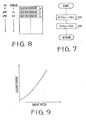
- FIG 9 shows the relationship between engine speed and clutch torque.
- the clutch torque increases exponentially with increase of engine speed. However, it is desirable to vary the speed of the engaging of the clutch in accordance with the rate of increase. of the engine speed, in order to reduce the shock at the engagement of the clutch.
- the present invention seeks to provide a system which controls clutch current in accordance with the magnitude of acceleration and deceleration of engine speed, so that a motor vehicle can be started smoothly.
- a system for controlling an electromagnetic clutch of an engine comprising engine speed sensing means for producing an engine speed signal dependent on the engine speed of the engine, vehicle speed sensing means for producing a vehicle speed signal in a low vehicle speed range, an accelerator pedal position sensor for producing an acceleration signal when an accelerator pedal of a motor vehicle is depressed, and selector lever position detecting means for producing a selector lever signal when the selector lever of a transmission is in positions other than the neutral and parking positions.
- the system further comprises circuit means for supplying clutch current to a magnetising coil of the electromagnetic clutch, and means responsive to the engine speed signal, vehicle speed signal, acceleration signal, and selector lever signal for controlling circuit means to decide the clutch current at the beginning of the engagement of the electromagnetic clutch.
- the clutch current increases as the acceleration of engine speed increases.
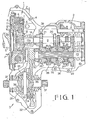
- the transmission system comprises an electromagnetic powder clutch 1, a four-speed transmission 2 and a final reduction device 3.
- the electromagnetic powder clutch 1 provided in a clutch case 4 comprises a drive plate 6 secured to the end of a crankshaft 5 of an internal combustion engine, an annular drive member 8 secured to the drive plate 6, a magnetising coil 7 provided in the drive member 8, and a driven member 10 secured by a spline engagement to an input shaft 9 of the transmission 2, leaving a gap 11 from the drive member 8 and driven member 10.
- Magnetic powder is provided in a powder chamber 12 and gap 11 is adapted to be filled with the powder.
- a cap 13 is secured to the drive member 8. The cap 13 has a cylindrical portion coaxial with the input shaft 9, on which slip rings 14 are securely provided. Slip rings 14'are connected to the drive member 8 by a lead X. Brushes 16 pressed against slip rings 14 are supported in a holder 17 and connected to a hereinafter described control system by a lead Y.
- the drive plate 6 and the drive member 8 rotate together with the crankshaft 5 and the magnetic powder sealed into the powder chamber 12 is moved on the inner surface of the drive member 8 by centrifugal force. If the magnetising coil 7 is excited by the current applied through the lead Y brushes 16, slip rings 14 and lead X, the drive member 8 is magnetised to produce a magnetic flux passing through the driven member 10. Thus, the powder is aggregated in the gap 11, so that the power of the engine is transmitted to the input shaft 9 through the clutch.
- 1st to 4th speed drive gears 18 to 21 are integrally provided on the input shaft 9.
- the drive gears 18 to 21 are engaged with driven gears 23 to 26, respectively.
- Driven gears 23 to 26 are rotatably mounted on the output shaft 22 parallel to the input shaft 9.
- Each of driven gears 23 and 24 is adapted to be engaged with the output shaft 22 by operating a synchroniser 27 and each of driven gears 25 and 26 is engaged with the output shaft 22 by a synchroniser 28 in the well known manner.
- a reverse drive gear means 29 is provided.
- the driven gear 23 is coupled selectively with the output shaft 22 by the synchroniser 27 and the first speed is obtained on the output shaft 22 and the speed of output shaft 9 is greatly decreased, and the second, third and fourth speed may be respectively obtained accordingly.
- an output gear 30 which engages with a ring gear 32 in a differential 31 of the final reduction device 3 to transmit the output of the output shaft 22 of the transmission 2 directly from ring gear 32 to side gears 36 through a case 33, a spider 34 and pinions 35, and further to driving wheels of a motor vehicle through wheel shafts 37.
- Figure 3 shows the control system which is provided with an engine speed sensor 48, vehicle speed sensor 50, accelerator pedal position sensor 52 for producing.an output signal dependent on the degree of the depression of an accelerator pedal of the motor vehicle, and select range sensor 53 for producing an output signal when the selector lever is positioned at drive positions, other than the neutral position and the parking positions, that is one of first to fourth speed positions or reverse position in the transmission of Figure 1.
- Output signals of sensors 48, 50 are applied to an input interface 56 of a microcomputer 41 through waveform shaping circuits 49, 51, respectively. Output signals of sensors 52 and 51 are also applied to the input interface 56.
- the microcomputer comprises a clock pulse generator 42, CPU 43, ROM 44, RAM 45, and output interface 47. The output of the microcomputer is converted to an analog signal by a D/A converter 54 and applied to the coil 7 through a driver 55.
- the control system of the present invention is adapted to control the characteristic of clutch torque in accordance with engine speed so as to smoothly start the motor vehicle.
- the clutch torque characteristic of the present invention is shown in Figure 4.
- a line A shows the slowest characteristic at the beginning of the depression of the accelerator pedal. Thereafter, the characteristic changes towards a line B as the magnitude of acceleration of engine speed increases. Namely, when the accelerator pedal is depressed rapidly, the clutch torque characteristic rapidly moves to the line B, and when the acceleration is small, the characteristic slowly moves to the line B.
- the acceleration zero, that is engine speed is constant, the characteristic is intermediate between lines A and B.
- engine speed decreases the characteristic moves to the line A.
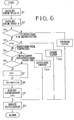
- step S 1 engine speed N is read out, and at step S 2 , vehicle speed V is read out.
- step S 3 it is determined whether the selector lever is in a driving position. If the selector lever is in the neutral position or parking position, the clutch current is cut off to disengage the clutch. If the selector lever is at a drive or reverse position, the program proceeds to a step S 4 , where it is determined whether the vehicle speed V is higher than a predetermined vehicle speed V L (10-25Km/h). If V is higher than V LI the rated clutch current flows passing the coil to entirely engage the clutch at a step S 13 .
- V L a predetermined vehicle speed
- step S 9 clutch current I(N) according to the value N i is derived from a table in the ROM 44.
- Figure 8 shows the table, in which clutch current is decided so as to produce clutch torque as shown in Figure 5.
- the coefficient C n is obtained by a subroutine shown in Figure 7, where n is the number of operations.
- the subroutine is initiated by a timer at intervals of a predetermined time A T (several m.sec. to 50 m.sec.).
- acceleration ⁇ of engine speed N is obtained by the operation of (N n-1 - N n ) for the interval A T.
- the coefficient C n is decided between zero and a limit value.
- control system employs a stepwise transmission
- an infinitely variable belt drive transmission can be employed for the system of the present invention.
- the present invention provides a system which controls the clutch current in accordance with the rate of variation of engine speed, whereby a motor vehicle can be smoothly started.
Landscapes
- Engineering & Computer Science (AREA)
- General Engineering & Computer Science (AREA)
- Physics & Mathematics (AREA)
- Mechanical Engineering (AREA)
- Fluid Mechanics (AREA)
- Electromagnetism (AREA)
- Hydraulic Clutches, Magnetic Clutches, Fluid Clutches, And Fluid Joints (AREA)
- Control Of Driving Devices And Active Controlling Of Vehicle (AREA)
- Electric Propulsion And Braking For Vehicles (AREA)
- Control Of Vehicle Engines Or Engines For Specific Uses (AREA)
Applications Claiming Priority (2)
| Application Number | Priority Date | Filing Date | Title |
|---|---|---|---|
| JP59193408A JPH0623026B2 (ja) | 1984-09-13 | 1984-09-13 | 車両用電磁式クラツチの制御方式 |
| JP193408/84 | 1984-09-13 |
Publications (3)
| Publication Number | Publication Date |
|---|---|
| EP0178781A2 true EP0178781A2 (de) | 1986-04-23 |
| EP0178781A3 EP0178781A3 (en) | 1986-06-25 |
| EP0178781B1 EP0178781B1 (de) | 1989-08-09 |
Family
ID=16307459
Family Applications (1)
| Application Number | Title | Priority Date | Filing Date |
|---|---|---|---|
| EP85306484A Expired EP0178781B1 (de) | 1984-09-13 | 1985-09-12 | Steueranlage für eine elektromagnetische Kraftfahrzeugkupplung |
Country Status (4)
| Country | Link |
|---|---|
| US (1) | US4723644A (de) |
| EP (1) | EP0178781B1 (de) |
| JP (1) | JPH0623026B2 (de) |
| DE (2) | DE3572142D1 (de) |
Cited By (6)
| Publication number | Priority date | Publication date | Assignee | Title |
|---|---|---|---|---|
| EP0251571A3 (en) * | 1986-06-18 | 1988-09-07 | Fuji Jukogyo Kabushiki Kaisha | Control system for a clutch for a vehicle |
| EP0251733A3 (de) * | 1986-06-28 | 1989-03-08 | Fuji Jukogyo Kabushiki Kaisha | Steuerung für eine Kupplung eines Fahrzeugs |
| GB2213550A (en) * | 1987-12-10 | 1989-08-16 | Kubota Ltd | Three-stage clutch control |
| EP0244222A3 (en) * | 1986-04-30 | 1989-11-02 | Fuji Jukogyo Kabushiki Kaisha | System for controlling a clutch for a motor vehicle |
| GB2225076A (en) * | 1988-11-08 | 1990-05-23 | Borg Warner Automotive | Clutch control system |
| EP1621437A3 (de) * | 2004-07-22 | 2007-04-18 | Luk Lamellen und Kupplungsbau GmbH | Verfahren und Einrichtung zum Steuern eines Antriebsstrangs eines Fahrzeugs |
Families Citing this family (14)
| Publication number | Priority date | Publication date | Assignee | Title |
|---|---|---|---|---|
| JPS62251248A (ja) * | 1986-04-24 | 1987-11-02 | Fuji Heavy Ind Ltd | 車両用自動クラツチの制御装置 |
| JP2603823B2 (ja) * | 1986-06-24 | 1997-04-23 | 富士重工業株式会社 | 車両用自動クラツチの制御装置 |
| JPH0626943B2 (ja) * | 1987-06-04 | 1994-04-13 | トヨタ自動車株式会社 | 車両用クラッチ制御装置 |
| DE3918254C2 (de) * | 1988-06-15 | 1998-04-30 | Volkswagen Ag | Verfahren zur Verhinderung von Lastwechselschlägen |
| JPH02256959A (ja) * | 1989-03-28 | 1990-10-17 | Aisin Seiki Co Ltd | 電子制御自動変速装置 |
| US5062049A (en) * | 1989-09-15 | 1991-10-29 | Borg-Warner Automotive, Inc. | Control method and apparatus for continuously variable transmissions |
| US5094332A (en) * | 1990-12-31 | 1992-03-10 | Dana Corporation | Digital control system for electromagnetic clutch |
| US5314050A (en) * | 1992-12-09 | 1994-05-24 | Eaton Corporation | Clutch mode control logic |
| GB9421324D0 (en) * | 1994-10-22 | 1994-12-07 | Automotive Products Plc | Clutch control system |
| FR2746353B1 (fr) * | 1996-03-21 | 2000-07-21 | Luk Getriebe Systeme Gmbh | Dispositif pour commander un systeme de transmission de couple |
| US6676562B1 (en) * | 2002-07-19 | 2004-01-13 | New Holland North America, Inc. | Automatic clutch engagement controlled by engine speed |
| US8398526B2 (en) * | 2008-01-17 | 2013-03-19 | Ford Global Technologies, Llc | Vehicle launch using a transmission clutch |
| US8056695B2 (en) * | 2008-07-10 | 2011-11-15 | Deere & Company | Adaptive soft start system for mower blade clutch engagement |
| CN107100947B (zh) * | 2017-05-15 | 2019-01-08 | 上海汽车变速器有限公司 | 湿式双离合器半结合点自学习优化方法及系统 |
Family Cites Families (15)
| Publication number | Priority date | Publication date | Assignee | Title |
|---|---|---|---|---|
| US2920726A (en) * | 1954-09-28 | 1960-01-12 | Ferodo Sa | Automatic clutches |
| US3134470A (en) * | 1959-10-19 | 1964-05-26 | Elmeg | Clutch control system |
| DE1505469B2 (de) * | 1965-10-02 | 1973-09-06 | Robert Bosch Gmbh, 7000 Stuttgart | Steuereinrichtung zum betrieb einer elektromagnetischen kraftfahrzeugkupplung. zusatz zu: 1223937 |
| DE3004930A1 (de) * | 1980-02-09 | 1981-08-20 | Volkswagenwerk Ag, 3180 Wolfsburg | Einrichtung zur automatischen kupplungsbetaetigung |
| JPS56131430A (en) * | 1980-03-15 | 1981-10-15 | Fuji Heavy Ind Ltd | Controller for electromagnetic powder type clutch of vehicle |
| JPS5722400A (en) * | 1980-07-16 | 1982-02-05 | Fuji Heavy Ind Ltd | Controlling device for magnetic clutch mounted on vehicle |
| JPS5737026A (en) * | 1980-08-12 | 1982-03-01 | Fuji Heavy Ind Ltd | Control device of electromagnetic clutch for vehicle |
| JPS5760921A (en) * | 1980-09-12 | 1982-04-13 | Fuji Heavy Ind Ltd | Controller in electromagnetic clutch for vehicle |
| JPS5766031A (en) * | 1980-10-11 | 1982-04-22 | Fuji Heavy Ind Ltd | Controlling device of electromagnetic clutch for vehicle |
| JPS5787722A (en) * | 1980-11-19 | 1982-06-01 | Fuji Heavy Ind Ltd | Control device for electromagnetic clutch for vehicle |
| JPS5790450A (en) * | 1980-11-27 | 1982-06-05 | Nippon Denso Co Ltd | Automatic change gear control apparatus for vehicle |
| JPS5790220A (en) * | 1980-11-28 | 1982-06-04 | Fuji Heavy Ind Ltd | Controller for vehicle's electromagnetic clutch |
| DE3364655D1 (en) * | 1982-04-28 | 1986-08-28 | Lucas Ind Plc | Automotive vehicle power transmission clutch control system |
| JPS5940048A (ja) * | 1982-08-31 | 1984-03-05 | Fuji Heavy Ind Ltd | オ−トクラツチ車の変速操作機構 |
| JPS60161224A (ja) * | 1984-01-31 | 1985-08-22 | Fuji Heavy Ind Ltd | 電磁式クラツチ付無段変速機のクラツチ制御装置 |
-
1984
- 1984-09-13 JP JP59193408A patent/JPH0623026B2/ja not_active Expired - Lifetime
-
1985
- 1985-09-09 US US06/774,253 patent/US4723644A/en not_active Expired - Fee Related
- 1985-09-12 EP EP85306484A patent/EP0178781B1/de not_active Expired
- 1985-09-12 DE DE8585306484T patent/DE3572142D1/de not_active Expired
- 1985-09-12 DE DE198585306484T patent/DE178781T1/de active Pending
Cited By (7)
| Publication number | Priority date | Publication date | Assignee | Title |
|---|---|---|---|---|
| EP0244222A3 (en) * | 1986-04-30 | 1989-11-02 | Fuji Jukogyo Kabushiki Kaisha | System for controlling a clutch for a motor vehicle |
| EP0251571A3 (en) * | 1986-06-18 | 1988-09-07 | Fuji Jukogyo Kabushiki Kaisha | Control system for a clutch for a vehicle |
| EP0251733A3 (de) * | 1986-06-28 | 1989-03-08 | Fuji Jukogyo Kabushiki Kaisha | Steuerung für eine Kupplung eines Fahrzeugs |
| GB2213550A (en) * | 1987-12-10 | 1989-08-16 | Kubota Ltd | Three-stage clutch control |
| GB2213550B (en) * | 1987-12-10 | 1991-09-11 | Kubota Ltd | Propelling clutch apparatus for a working vehicle |
| GB2225076A (en) * | 1988-11-08 | 1990-05-23 | Borg Warner Automotive | Clutch control system |
| EP1621437A3 (de) * | 2004-07-22 | 2007-04-18 | Luk Lamellen und Kupplungsbau GmbH | Verfahren und Einrichtung zum Steuern eines Antriebsstrangs eines Fahrzeugs |
Also Published As
| Publication number | Publication date |
|---|---|
| EP0178781A3 (en) | 1986-06-25 |
| JPS6171231A (ja) | 1986-04-12 |
| DE178781T1 (de) | 1986-09-04 |
| JPH0623026B2 (ja) | 1994-03-30 |
| US4723644A (en) | 1988-02-09 |
| DE3572142D1 (en) | 1989-09-14 |
| EP0178781B1 (de) | 1989-08-09 |
Similar Documents
| Publication | Publication Date | Title |
|---|---|---|
| EP0178781B1 (de) | Steueranlage für eine elektromagnetische Kraftfahrzeugkupplung | |
| US4905801A (en) | Control system for a clutch for a motor vehicle | |
| US4502579A (en) | System for preventing the overheat of a clutch for an internal combustion engine | |
| EP0151038B1 (de) | Steueranlage für eine elektromagnetische Kupplung eines Fahrzeugs | |
| EP0754888A3 (de) | Einrichtung zur Abschätzung des Drehmoments an einer Achse | |
| EP0178060B1 (de) | Steuerung einer elektromagnetischen Kupplung für Kraftwagen | |
| US4494641A (en) | Electromagnetic clutch control system for automobiles | |
| GB2084280A (en) | Preventing overheating of electromagnetic clutch of vehicle | |
| EP0153051B1 (de) | Steueranlage für eine elektromagnetische Kupplung eines Fahrzeuges | |
| US4403683A (en) | Electro-magnetic powder clutch system for automobiles | |
| EP0719394B1 (de) | Verfahren zur steuerung einer antriebsanordnung für kraftfahrzeuge mit einem stufenlos regelbaren getriebe | |
| US4449617A (en) | Electro-magnetic clutch control system for automobiles | |
| EP0108507B1 (de) | Steuervorrichtung für ein Getriebe mit stufenlos veränderbarer Übersetzung, das mit einer Elektromagnetpulverkupplung versehen ist | |
| US4480732A (en) | Electro-magnetic clutch control system for automobiles | |
| EP0172601B1 (de) | Steuereinrichtung für ein Kraftfahrzeug-Antriebsaggregat | |
| US4494639A (en) | Electro-magnetic clutch control system for automobiles | |
| EP0147200A2 (de) | Steuerungsanlage für das Drehmoment einer Fahrzeugkupplung | |
| US4449620A (en) | Electromagnetic clutch control system for vehicles | |
| US4675818A (en) | System for controlling an electromagnetic clutch for an automotive engine | |
| EP0251571B1 (de) | Fahrzeugkupplungssteuersystem | |
| GB2088009A (en) | Controlling Electromagnetic Clutch of Vehicle | |
| EP0240284B1 (de) | Steuersystem für eine elektromagnetische Fahrzeugkupplung | |
| JPH01297327A (ja) | 車両変速装置 | |
| JPS6358126B2 (de) | ||
| JPH0642896Y2 (ja) | 車両用電磁式クラッチの制御装置 |
Legal Events
| Date | Code | Title | Description |
|---|---|---|---|
| PUAI | Public reference made under article 153(3) epc to a published international application that has entered the european phase |
Free format text: ORIGINAL CODE: 0009012 |
|
| 17P | Request for examination filed |
Effective date: 19850919 |
|
| AK | Designated contracting states |
Kind code of ref document: A2 Designated state(s): DE GB IT NL |
|
| PUAL | Search report despatched |
Free format text: ORIGINAL CODE: 0009013 |
|
| ITCL | It: translation for ep claims filed |
Representative=s name: STUDIO BIANCHETTI |
|
| TCNL | Nl: translation of patent claims filed | ||
| AK | Designated contracting states |
Kind code of ref document: A3 Designated state(s): DE GB IT NL |
|
| DET | De: translation of patent claims | ||
| 17Q | First examination report despatched |
Effective date: 19871211 |
|
| GRAA | (expected) grant |
Free format text: ORIGINAL CODE: 0009210 |
|
| AK | Designated contracting states |
Kind code of ref document: B1 Designated state(s): DE GB IT NL |
|
| REF | Corresponds to: |
Ref document number: 3572142 Country of ref document: DE Date of ref document: 19890914 |
|
| ITF | It: translation for a ep patent filed | ||
| PLBE | No opposition filed within time limit |
Free format text: ORIGINAL CODE: 0009261 |
|
| STAA | Information on the status of an ep patent application or granted ep patent |
Free format text: STATUS: NO OPPOSITION FILED WITHIN TIME LIMIT |
|
| 26N | No opposition filed | ||
| PGFP | Annual fee paid to national office [announced via postgrant information from national office to epo] |
Ref country code: GB Payment date: 19910906 Year of fee payment: 7 |
|
| PGFP | Annual fee paid to national office [announced via postgrant information from national office to epo] |
Ref country code: DE Payment date: 19910926 Year of fee payment: 7 |
|
| ITTA | It: last paid annual fee | ||
| PGFP | Annual fee paid to national office [announced via postgrant information from national office to epo] |
Ref country code: NL Payment date: 19910930 Year of fee payment: 7 |
|
| PG25 | Lapsed in a contracting state [announced via postgrant information from national office to epo] |
Ref country code: GB Effective date: 19920912 |
|
| PG25 | Lapsed in a contracting state [announced via postgrant information from national office to epo] |
Ref country code: NL Effective date: 19930401 |
|
| GBPC | Gb: european patent ceased through non-payment of renewal fee |
Effective date: 19920912 |
|
| NLV4 | Nl: lapsed or anulled due to non-payment of the annual fee | ||
| PG25 | Lapsed in a contracting state [announced via postgrant information from national office to epo] |
Ref country code: DE Effective date: 19930602 |