EP0179768B1 - Gas/flüssigkeits-kontakt zur austreibung unerwünschten gases - Google Patents
Gas/flüssigkeits-kontakt zur austreibung unerwünschten gases Download PDFInfo
- Publication number
- EP0179768B1 EP0179768B1 EP84902717A EP84902717A EP0179768B1 EP 0179768 B1 EP0179768 B1 EP 0179768B1 EP 84902717 A EP84902717 A EP 84902717A EP 84902717 A EP84902717 A EP 84902717A EP 0179768 B1 EP0179768 B1 EP 0179768B1
- Authority
- EP
- European Patent Office
- Prior art keywords
- gas
- liquid
- separation chamber
- gas ejector
- ejector
- Prior art date
- Legal status (The legal status is an assumption and is not a legal conclusion. Google has not performed a legal analysis and makes no representation as to the accuracy of the status listed.)
- Expired
Links
- 239000007788 liquid Substances 0.000 title claims abstract description 56
- 239000007789 gas Substances 0.000 claims abstract description 106
- 238000000926 separation method Methods 0.000 claims abstract description 37
- 239000000203 mixture Substances 0.000 claims abstract description 13
- 238000004140 cleaning Methods 0.000 claims description 11
- 238000000034 method Methods 0.000 claims description 8
- 238000004064 recycling Methods 0.000 claims description 3
- 238000007599 discharging Methods 0.000 claims description 2
- IJGRMHOSHXDMSA-UHFFFAOYSA-N Atomic nitrogen Chemical compound N#N IJGRMHOSHXDMSA-UHFFFAOYSA-N 0.000 abstract description 44
- 229910052757 nitrogen Inorganic materials 0.000 abstract description 22
- 239000001301 oxygen Substances 0.000 abstract description 21
- 229910052760 oxygen Inorganic materials 0.000 abstract description 21
- QVGXLLKOCUKJST-UHFFFAOYSA-N atomic oxygen Chemical compound [O] QVGXLLKOCUKJST-UHFFFAOYSA-N 0.000 abstract description 20
- 239000013535 sea water Substances 0.000 abstract description 14
- 230000003197 catalytic effect Effects 0.000 abstract description 8
- 238000003795 desorption Methods 0.000 abstract description 3
- 230000002708 enhancing effect Effects 0.000 abstract 1
- CURLTUGMZLYLDI-UHFFFAOYSA-N Carbon dioxide Chemical compound O=C=O CURLTUGMZLYLDI-UHFFFAOYSA-N 0.000 description 4
- XLYOFNOQVPJJNP-UHFFFAOYSA-N water Substances O XLYOFNOQVPJJNP-UHFFFAOYSA-N 0.000 description 4
- 229910002092 carbon dioxide Inorganic materials 0.000 description 2
- 239000001569 carbon dioxide Substances 0.000 description 2
- 238000006243 chemical reaction Methods 0.000 description 2
- 239000007791 liquid phase Substances 0.000 description 2
- 238000004519 manufacturing process Methods 0.000 description 2
- QSHDDOUJBYECFT-UHFFFAOYSA-N mercury Chemical compound [Hg] QSHDDOUJBYECFT-UHFFFAOYSA-N 0.000 description 2
- 229910052753 mercury Inorganic materials 0.000 description 2
- 230000003647 oxidation Effects 0.000 description 2
- 238000007254 oxidation reaction Methods 0.000 description 2
- UGFAIRIUMAVXCW-UHFFFAOYSA-N Carbon monoxide Chemical compound [O+]#[C-] UGFAIRIUMAVXCW-UHFFFAOYSA-N 0.000 description 1
- RWSOTUBLDIXVET-UHFFFAOYSA-N Dihydrogen sulfide Chemical compound S RWSOTUBLDIXVET-UHFFFAOYSA-N 0.000 description 1
- 229910019142 PO4 Inorganic materials 0.000 description 1
- QAOWNCQODCNURD-UHFFFAOYSA-N Sulfuric acid Chemical compound OS(O)(=O)=O QAOWNCQODCNURD-UHFFFAOYSA-N 0.000 description 1
- 238000010521 absorption reaction Methods 0.000 description 1
- 238000010564 aerobic fermentation Methods 0.000 description 1
- 230000031018 biological processes and functions Effects 0.000 description 1
- 229910002091 carbon monoxide Inorganic materials 0.000 description 1
- 239000013505 freshwater Substances 0.000 description 1
- 238000005984 hydrogenation reaction Methods 0.000 description 1
- JCXJVPUVTGWSNB-UHFFFAOYSA-N nitrogen dioxide Inorganic materials O=[N]=O JCXJVPUVTGWSNB-UHFFFAOYSA-N 0.000 description 1
- QJGQUHMNIGDVPM-UHFFFAOYSA-N nitrogen group Chemical group [N] QJGQUHMNIGDVPM-UHFFFAOYSA-N 0.000 description 1
- 239000003129 oil well Substances 0.000 description 1
- 150000002926 oxygen Chemical class 0.000 description 1
- 235000021317 phosphate Nutrition 0.000 description 1
- 150000003013 phosphoric acid derivatives Chemical class 0.000 description 1
- 230000003134 recirculating effect Effects 0.000 description 1
- 238000007670 refining Methods 0.000 description 1
- 238000005201 scrubbing Methods 0.000 description 1
- 239000002904 solvent Substances 0.000 description 1
- 239000007921 spray Substances 0.000 description 1
- 239000000126 substance Substances 0.000 description 1
- 239000001117 sulphuric acid Substances 0.000 description 1
- 235000011149 sulphuric acid Nutrition 0.000 description 1
- 230000005514 two-phase flow Effects 0.000 description 1
Images
Classifications
-
- B—PERFORMING OPERATIONS; TRANSPORTING
- B01—PHYSICAL OR CHEMICAL PROCESSES OR APPARATUS IN GENERAL
- B01D—SEPARATION
- B01D19/00—Degasification of liquids
- B01D19/0042—Degasification of liquids modifying the liquid flow
- B01D19/0047—Atomizing, spraying, trickling
-
- B—PERFORMING OPERATIONS; TRANSPORTING
- B01—PHYSICAL OR CHEMICAL PROCESSES OR APPARATUS IN GENERAL
- B01D—SEPARATION
- B01D19/00—Degasification of liquids
- B01D19/0005—Degasification of liquids with one or more auxiliary substances
-
- C—CHEMISTRY; METALLURGY
- C02—TREATMENT OF WATER, WASTE WATER, SEWAGE, OR SLUDGE
- C02F—TREATMENT OF WATER, WASTE WATER, SEWAGE, OR SLUDGE
- C02F1/00—Treatment of water, waste water, or sewage
- C02F1/20—Treatment of water, waste water, or sewage by degassing, i.e. liberation of dissolved gases
Definitions
- the invention relates to the contact and mass transfer of gas into a liquid with particular application to extract dissolved oxygen from sea water by dissolving nitrogen in its place.
- the deoxygenated sea water is then pumped into oil wells drilled in the sea bed.
- Typical examples of the equipment used for such reactions are packed columns, spray columns, plate columns or mechanically agitated vessels.
- the present invention is concerned with new apparatus which has been developed for the desorption of a gas using a liquid phase process where one gas is replaced in solution by another.
- GB-A-1531537 discloses apparatus for extracting a dissolved first gas from a liquid comprising mixing means, applied with the liquid and a second gas, for dissolving the second gas in the liquid and separation means for separating a mixture of free first and second gases from the liquid.
- the second gas is fed together with the liquid to a mixer whose output is fed to a cyclone separator.
- the mixing means comprises a liquid conduit for conveying the liquid and provided with at least one main gas ejector to which the second gas is supplied separately from the liquid, the apparatus further comprising second separation means associated with the or each main gas ejector for removing said first gas from said mixture conveyed from the first separation means, the or each main gas ejector being operable so as to provide sufficient suction to draw first and second gases from the first separation means to the associated second separation means.
- the invention also provides a method of extracting a dissolved first gas from a liquid, including the steps of dissolving a second gas in the liquid separating a mixture of free first and second gases from the liquid in first separation means, the invention comprising performing said dissolving step by passing the liquid through at least one main gas ejector provided in a liquid conduit and the ejector being supplied with the second gas separately from said liquid; conveying at least part of the mixture from the first separation means to second separation means associated with the or each main gas ejector for removing first gas ejector being operated so as to provide sufficient suction to draw first and second gases from the first separation means and into the second separation means.
- WO-A-83/02402 a document published prior to the filing date but later than the priority date of this application, discloses a recirculating device for extracting gas from liquid, including gas ejectors, but does not disclose cleaning means associated with gas ejectors.
- DE-A-3143459 discloses mixing means comprising a liquid conduit for conveying the liquid and provided with at least one main gas ejector to which the second gas is supplied separately from the liquid, in providing ejectors for supplying nitrogen or carbon dioxide.
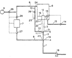
- sea water containing dissolved oxygen is pumped by a pump 18 through an inlet pipe 1 to a main gas ejector 4 comprising a convergent nozzle 19 connected to the inlet pipe 1, a mixing chamber 20 opening into a mixing tube 2, and a first gas pipe 8 for supplying nitrogen to the mixing chamber 20.
- Liquid flow through the main gas ejector 4 creates a low pressure region within the chamber 20 and so nitrogen is drawn into the chamber 20 and mixes with the sea water as it passes up the mixing tube 2.
- the resultant liquid/ gas mixture then discharges into an auxiliary gas ejector 5 formed by the lower, inlet end 11 of a mixing tube 3 which surrounds the outlet end 21 of the mains gas ejector mixing tube 2 and is provided with a second gas pipe 10.
- Flow of liquid through the auxiliary gas ejector 5 creates a low pressure region in the inlet end 11 of the mixing tube 3 and thus draws in further gas from the gas pipe 10.
- the resultant liquid/gas mixture passes up the mixing tube 3 and discharges from the mixing tube 3 into a separation chamber 6 surrounding the upper, outlet end 12 of the mixing tube 3.
- the cross section of the mixing tube 3 is increased at steps 22 and 23 provided to cause additional turbulence and to retard the flow.
- the sea water passes vertically upwards through the main and auxiliary gas ejectors 4 and 5, this is not necessary at the high rates of liquid flow during normal operation. Similarly, it is not necessary for the mixing tube 3 to extend vertically into the separation vessel 6.
- Sea water is removed from the separation chamber 6 through an outlet pipe 13 through a valve 14 controlled by a float sensor 15, the valve 14 and sensor 15 operating to maintain the level 16 of sea water 17 within the separation chamber 6 between predetermined limits.
- the free gas issuing into the separation chamber 6 contains a proportion of unwanted oxygen which has been arranged from solution in the sea water and this gas mixture leaves the separation chamber 6 through outlet 24 and is split into two streams flowing in pipes 8 and 10 providing main and auxiliary recycling means respectively associated with the main gas ejector 4 and the auxiliary ejector 5.
- the stream passing through pipe 8 also passes through a catalytic burner 7 which receives the unwanted oxygen whereas the stream passing through pipe 10 passes to the auxiliary gas ejector 5.
- the flow rate in the pipe 10 is monitored by a flow meter 25 which controls a valve 26, whereas the flow rate in the pipe 8 is monitored by a flow meter 27 and controlled by v l lve 28 and 29, the valve 29 controlling the flow of pure nitrogen from a separate source 9 in order to make up for the oxygen removed in the catalytic burner 7.
- the source 9 of pure nitrogen may be omitted and fresh air may be admitted into the system via valve 29. In this case, unwanted oxygen is removed in the catalytic burner 7 so that the gas fed through the first gas pipe 8 is predominantly nitrogen, as required.
- Nitrogen flow rates are two litres per second through first and second gas pipes 8 and 10 and two litres per second through the catalytic burner 7.
- the catalytic burner must remove the oxygen released from the water, namely 9.75 mg per second and approximately 5 mg per second nitrogen will be required to replace the nitrogen dissolved in the water in place of the oxygen. This can be supplied by passing 6.25 mg per second of air through the valve 29 which, on passing through the catalytic burner 7 will have the oxygen removed, leaving 5 mg per second nitrogen.
Landscapes
- Chemical & Material Sciences (AREA)
- Chemical Kinetics & Catalysis (AREA)
- Life Sciences & Earth Sciences (AREA)
- Hydrology & Water Resources (AREA)
- Engineering & Computer Science (AREA)
- Environmental & Geological Engineering (AREA)
- Water Supply & Treatment (AREA)
- Organic Chemistry (AREA)
- Gas Separation By Absorption (AREA)
- Physical Or Chemical Processes And Apparatus (AREA)
Claims (10)
gekennzeichnet durch:
dadurch gekennzeichnet, dass
Priority Applications (1)
| Application Number | Priority Date | Filing Date | Title |
|---|---|---|---|
| AT84902717T ATE42908T1 (de) | 1983-07-07 | 1984-07-09 | Gas/fluessigkeits-kontakt zur austreibung unerwuenschten gases. |
Applications Claiming Priority (2)
| Application Number | Priority Date | Filing Date | Title |
|---|---|---|---|
| GB08318450A GB2145937A (en) | 1983-07-07 | 1983-07-07 | Contacting a gas and a liquid to remove an unwanted gas |
| GB8318450 | 1983-07-07 |
Publications (2)
| Publication Number | Publication Date |
|---|---|
| EP0179768A1 EP0179768A1 (de) | 1986-05-07 |
| EP0179768B1 true EP0179768B1 (de) | 1989-05-10 |
Family
ID=10545397
Family Applications (1)
| Application Number | Title | Priority Date | Filing Date |
|---|---|---|---|
| EP84902717A Expired EP0179768B1 (de) | 1983-07-07 | 1984-07-09 | Gas/flüssigkeits-kontakt zur austreibung unerwünschten gases |
Country Status (5)
| Country | Link |
|---|---|
| US (1) | US4612021A (de) |
| EP (1) | EP0179768B1 (de) |
| DE (1) | DE3478089D1 (de) |
| GB (1) | GB2145937A (de) |
| WO (1) | WO1985000298A1 (de) |
Families Citing this family (38)
| Publication number | Priority date | Publication date | Assignee | Title |
|---|---|---|---|---|
| FR2565576B1 (fr) * | 1984-06-06 | 1989-12-22 | Petroles Cie Francaise | Procede de desaeration d'eau |
| NO158283C (no) * | 1986-02-13 | 1988-08-17 | Norsk Hydro As | Fremgangsmaate og anordning for behandling av blandinger vaeske/gass. |
| NO881045L (no) * | 1987-03-18 | 1988-09-19 | Mobil Oil Corp | Fremgangsmaate for fjerning av opploest gass fra en vaeske. |
| US4861352A (en) * | 1987-12-30 | 1989-08-29 | Union Carbide Corporation | Method of separating a gas and/or particulate matter from a liquid |
| CH675996A5 (de) * | 1988-01-28 | 1990-11-30 | Sulzer Ag | |
| US5035462A (en) * | 1988-09-30 | 1991-07-30 | Hynbrood Pty. Limited | Utility vehicle chassis having a vertically adjustable bed |
| US5078977A (en) * | 1988-10-21 | 1992-01-07 | Cyprus Minerals Company | Cyanide recovery process |
| EP0391839B1 (de) * | 1989-04-05 | 1992-06-03 | GebràDer Sulzer Aktiengesellschaft | Verfahren zum Anfahren eines Prozesses zum Deoxidieren von Wasser, insbesondere von Meerwasser |
| US5207875A (en) * | 1989-05-12 | 1993-05-04 | University Of Hawaii | Seawater pre-deaerator process for open-cycle ocean thermal energy conversion applications |
| US5096544A (en) * | 1989-05-12 | 1992-03-17 | The Research Corporation Of The University Of Hawaii | Seawater pre-deaerator for open-cycle ocean thermal energy conversion applications |
| US5112357A (en) * | 1990-10-05 | 1992-05-12 | Universal Beverage Equipment, Inc. | Deoxygenation system and method |
| JPH0673603B2 (ja) * | 1990-11-26 | 1994-09-21 | 野村マイクロ・サイエンス株式会社 | 純水または超純水中の溶存酸素の除去方法 |
| DE4115050A1 (de) * | 1991-05-08 | 1992-11-12 | Sihi Gmbh & Co Kg | Verfahren zur trocknung und entgasung von fluessigkeiten |
| JPH0564706A (ja) * | 1991-09-06 | 1993-03-19 | Ngk Insulators Ltd | 脱酸素水の製造装置 |
| EP0646400B1 (de) * | 1993-04-14 | 2001-07-18 | Nippon Sanso Corporation | Vorrichtung zur herabsetzung vom gelöstem sauerstoff |
| US6423235B1 (en) * | 1999-08-18 | 2002-07-23 | Nittetu Chemical Engineering Ltd. | Column gas-liquid contacting apparatus and its use thereof |
| NO314625B1 (no) * | 1999-11-15 | 2003-04-22 | Forinnova As | Fremgangsmåte og apparat for å behandle vannsystemer |
| EP1373144B1 (de) | 2001-04-05 | 2005-08-03 | Petreco International, Inc. | Einrichtung zum mechanischen abtrennen von sauerstoff |
| SE0102705D0 (sv) * | 2001-08-13 | 2001-08-13 | Armen Avetian | Sektionellt sammansatt luftare för anrikningsmaskiner samt för avloppsvatten |
| RU2223228C2 (ru) * | 2002-04-08 | 2004-02-10 | ЗАО "Гагарка-Аи-ПВ" | Способ и установка для выделения и утилизации хлора при выщелачивании металлов |
| US20030205136A1 (en) * | 2002-05-02 | 2003-11-06 | Mcnulty Peter Drummond | System and method of water treatment |
| CN1649796A (zh) * | 2002-05-02 | 2005-08-03 | P·D·麦克纳帝 | 水处理系统及方法 |
| EP1751063A1 (de) * | 2004-05-11 | 2007-02-14 | Metafil AS | Ballastwassersystem |
| JP2008523349A (ja) * | 2004-12-07 | 2008-07-03 | ウエストレイク・ペトロケミカルズ・エル・ピー | ボイラー給水の脱気の方法及び装置 |
| US7438809B2 (en) * | 2005-02-02 | 2008-10-21 | Petreco International Inc. | Single-cell mechanical flotation system |
| US7416661B2 (en) * | 2005-04-01 | 2008-08-26 | Petreco International Inc. | Mechanical flotation device for reduction of oil, alkalinity and undesirable gases |
| US8173016B2 (en) | 2005-04-01 | 2012-05-08 | Cameron International Corporation | Mechanical flotation device for reduction of oil, alkalinity and undesirable gases |
| DE102005023549A1 (de) * | 2005-05-21 | 2006-11-23 | Oxeno Olefinchemie Gmbh | Verfahren zur Oligomerisierung von Butenen |
| CN101553434B (zh) * | 2006-10-20 | 2012-10-10 | 海洋救护者公司 | 液体处理方法和装置 |
| US8449656B2 (en) * | 2010-11-16 | 2013-05-28 | Amt International Inc. | Process and apparatus for removal of oxygen from seawater |
| BR112013030212B1 (pt) * | 2011-05-24 | 2021-05-18 | Parker-Hannifin Corporation | dispositivo de desaeração e método de desaeração de fluido hidráulico |
| WO2016046016A1 (en) * | 2014-09-26 | 2016-03-31 | Odor Control Europe Ab | Arrangement for treatment of waste water |
| CN104314609B (zh) * | 2014-09-28 | 2016-05-25 | 太原理工大学 | 一种用于瓦斯抽采钻井的冷热交替增产方法 |
| CN104314608B (zh) * | 2014-09-28 | 2016-05-25 | 太原理工大学 | 一种提高煤层瓦斯抽采量的冷热交替系统 |
| NO20160356A1 (en) | 2016-03-02 | 2017-06-12 | Minox Tech As | Method and apparatus for removal of oxygen from seawater |
| WO2020212502A1 (en) * | 2019-04-16 | 2020-10-22 | Minox Technology As | System and method for mixing gas and fluids |
| NO345441B1 (en) | 2019-06-25 | 2021-02-01 | Minox Tech As | System and method for removal of oxygen from water |
| US12281029B2 (en) | 2022-03-21 | 2025-04-22 | Saudi Arabian Oil Company | Model predictive control system and method using neural network to control dissolved oxygen and PH in seawater |
Family Cites Families (9)
| Publication number | Priority date | Publication date | Assignee | Title |
|---|---|---|---|---|
| GB1028821A (en) * | 1962-12-20 | 1966-05-11 | Nat Res Dev | Improved deaerator |
| US3815330A (en) * | 1973-02-22 | 1974-06-11 | C Lawley | Apparatus for removing oxygen from liquids |
| US4023941A (en) * | 1974-04-22 | 1977-05-17 | The British Hydromechanics Research Association | Gas desorption from liquids |
| CH598142A5 (de) * | 1976-03-24 | 1978-04-28 | Bbc Brown Boveri & Cie | |
| GB1531537A (en) * | 1976-03-26 | 1978-11-08 | British Petroleum Co | Degassing treatment of liquid |
| US4136747A (en) * | 1976-12-17 | 1979-01-30 | Loffland Brothers Company | Method and means for reduction of oxygen content in drilling fluid |
| DE3143459C2 (de) * | 1981-11-03 | 1985-10-24 | Füllpack Dipl.-Brauerei-Ing. Dieter Wieland, 4000 Düsseldorf | Verfahren zur Austreibung von gelösten Gasen, insbesondere Sauerstoff aus Flüssigkeiten, insbesondere Wasser, sowie Vorrichtung zur Durchführung des Verfahrens |
| JPS59500165A (ja) * | 1982-01-15 | 1984-02-02 | ザ・ブリティッシュ・ハイドロメカニックス・リサ−チ・アソシエ−ション | 液体中のガス抽出 |
| US4415341A (en) * | 1982-05-13 | 1983-11-15 | Conoco Inc. | Gas, liquid contactor |
-
1983
- 1983-07-07 GB GB08318450A patent/GB2145937A/en not_active Withdrawn
-
1984
- 1984-07-09 US US06/711,569 patent/US4612021A/en not_active Expired - Fee Related
- 1984-07-09 EP EP84902717A patent/EP0179768B1/de not_active Expired
- 1984-07-09 WO PCT/GB1984/000243 patent/WO1985000298A1/en not_active Ceased
- 1984-07-09 DE DE8484902717T patent/DE3478089D1/de not_active Expired
Also Published As
| Publication number | Publication date |
|---|---|
| WO1985000298A1 (en) | 1985-01-31 |
| GB2145937A (en) | 1985-04-11 |
| US4612021A (en) | 1986-09-16 |
| GB8318450D0 (en) | 1983-08-10 |
| DE3478089D1 (en) | 1989-06-15 |
| EP0179768A1 (de) | 1986-05-07 |
Similar Documents
| Publication | Publication Date | Title |
|---|---|---|
| US4612021A (en) | Contacting a gas and a liquid to remove an unwanted gas | |
| US8486338B2 (en) | Gas-liquid contactor | |
| US4211733A (en) | Gas-liquid mixing process and apparatus | |
| EP0234771B1 (de) | Verfahren und Vorrichtung zur Behandlung von Flüssigkeit-Gasmischungen | |
| JP4083839B2 (ja) | クメン酸化プロセス | |
| EP1021237A1 (de) | System zur fluidtrennung | |
| US6562240B1 (en) | Mixing apparatus | |
| US10143939B2 (en) | Cleaning of oleaginous water III | |
| US3243046A (en) | Floatation apparatus | |
| US6299776B1 (en) | Biochemical oxidation system and process | |
| US4220612A (en) | Flotation cell feed duct | |
| CN104787981A (zh) | 一种dmto装置低bc比废水的深度处理方法及处理装置 | |
| CN101330954B (zh) | 重力分离器和用于分离含有水、油以及气体的混合物的方法 | |
| EP0965379A1 (de) | Verfahren zur herstellung von absorbierender entschwefelungsflüssigkeit und vorrichtung dazu | |
| JPH0113896B2 (de) | ||
| US5147620A (en) | Process for the purification of gaseous streams | |
| CA1157587A (en) | Process and apparatus for absorbing ozone | |
| CA2042630A1 (en) | Method and apparatus for beneficiating waste-waters | |
| CS215043B2 (en) | Facility for cleaning and/or aerating the water | |
| CN101734737B (zh) | 一种乙烯装置工艺水汽提塔出水的处理方法 | |
| SU996333A1 (ru) | Способ флотационной очистки воды | |
| US6277247B1 (en) | Operation method of a plant for distilling liquid products and plant for realizing the same | |
| US4391713A (en) | Reverse osmosis unit-degasifier system | |
| SU1142449A1 (ru) | Аппарат дл очистки промышленных фенольных сточных вод | |
| JP3223132B2 (ja) | 液−液抽出装置 |
Legal Events
| Date | Code | Title | Description |
|---|---|---|---|
| PUAI | Public reference made under article 153(3) epc to a published international application that has entered the european phase |
Free format text: ORIGINAL CODE: 0009012 |
|
| 17P | Request for examination filed |
Effective date: 19860106 |
|
| AK | Designated contracting states |
Kind code of ref document: A1 Designated state(s): AT BE CH DE FR GB LI LU NL SE |
|
| 17Q | First examination report despatched |
Effective date: 19861010 |
|
| D17Q | First examination report despatched (deleted) | ||
| GRAA | (expected) grant |
Free format text: ORIGINAL CODE: 0009210 |
|
| AK | Designated contracting states |
Kind code of ref document: B1 Designated state(s): AT BE CH DE FR GB LI LU NL SE |
|
| PG25 | Lapsed in a contracting state [announced via postgrant information from national office to epo] |
Ref country code: SE Effective date: 19890510 Ref country code: NL Effective date: 19890510 Ref country code: LI Effective date: 19890510 Ref country code: FR Free format text: THE PATENT HAS BEEN ANNULLED BY A DECISION OF A NATIONAL AUTHORITY Effective date: 19890510 Ref country code: CH Effective date: 19890510 Ref country code: BE Effective date: 19890510 Ref country code: AT Effective date: 19890510 |
|
| REF | Corresponds to: |
Ref document number: 42908 Country of ref document: AT Date of ref document: 19890515 Kind code of ref document: T |
|
| REF | Corresponds to: |
Ref document number: 3478089 Country of ref document: DE Date of ref document: 19890615 |
|
| PG25 | Lapsed in a contracting state [announced via postgrant information from national office to epo] |
Ref country code: LU Free format text: LAPSE BECAUSE OF NON-PAYMENT OF DUE FEES Effective date: 19890731 |
|
| REG | Reference to a national code |
Ref country code: CH Ref legal event code: PL |
|
| EN | Fr: translation not filed | ||
| NLV1 | Nl: lapsed or annulled due to failure to fulfill the requirements of art. 29p and 29m of the patents act | ||
| PLBE | No opposition filed within time limit |
Free format text: ORIGINAL CODE: 0009261 |
|
| STAA | Information on the status of an ep patent application or granted ep patent |
Free format text: STATUS: NO OPPOSITION FILED WITHIN TIME LIMIT |
|
| 26N | No opposition filed | ||
| PGFP | Annual fee paid to national office [announced via postgrant information from national office to epo] |
Ref country code: GB Payment date: 19920626 Year of fee payment: 9 |
|
| PGFP | Annual fee paid to national office [announced via postgrant information from national office to epo] |
Ref country code: DE Payment date: 19920727 Year of fee payment: 9 |
|
| PG25 | Lapsed in a contracting state [announced via postgrant information from national office to epo] |
Ref country code: GB Effective date: 19930709 |
|
| GBPC | Gb: european patent ceased through non-payment of renewal fee |
Effective date: 19930709 |
|
| PG25 | Lapsed in a contracting state [announced via postgrant information from national office to epo] |
Ref country code: DE Effective date: 19940401 |