EP0180326A2 - Cage de laminoir - Google Patents
Cage de laminoir Download PDFInfo
- Publication number
- EP0180326A2 EP0180326A2 EP85306911A EP85306911A EP0180326A2 EP 0180326 A2 EP0180326 A2 EP 0180326A2 EP 85306911 A EP85306911 A EP 85306911A EP 85306911 A EP85306911 A EP 85306911A EP 0180326 A2 EP0180326 A2 EP 0180326A2
- Authority
- EP
- European Patent Office
- Prior art keywords
- bearings
- roll
- shafts
- rolling mill
- tandem
- Prior art date
- Legal status (The legal status is an assumption and is not a legal conclusion. Google has not performed a legal analysis and makes no representation as to the accuracy of the status listed.)
- Withdrawn
Links
Images


Classifications
-
- B—PERFORMING OPERATIONS; TRANSPORTING
- B21—MECHANICAL METAL-WORKING WITHOUT ESSENTIALLY REMOVING MATERIAL; PUNCHING METAL
- B21B—ROLLING OF METAL
- B21B31/00—Rolling stand structures; Mounting, adjusting, or interchanging rolls, roll mountings, or stand frames
- B21B31/07—Adaptation of roll neck bearings
-
- F—MECHANICAL ENGINEERING; LIGHTING; HEATING; WEAPONS; BLASTING
- F16—ENGINEERING ELEMENTS AND UNITS; GENERAL MEASURES FOR PRODUCING AND MAINTAINING EFFECTIVE FUNCTIONING OF MACHINES OR INSTALLATIONS; THERMAL INSULATION IN GENERAL
- F16C—SHAFTS; FLEXIBLE SHAFTS; ELEMENTS OR CRANKSHAFT MECHANISMS; ROTARY BODIES OTHER THAN GEARING ELEMENTS; BEARINGS
- F16C23/00—Bearings for exclusively rotary movement adjustable for aligning or positioning
- F16C23/02—Sliding-contact bearings
- F16C23/04—Sliding-contact bearings self-adjusting
-
- B—PERFORMING OPERATIONS; TRANSPORTING
- B21—MECHANICAL METAL-WORKING WITHOUT ESSENTIALLY REMOVING MATERIAL; PUNCHING METAL
- B21B—ROLLING OF METAL
- B21B13/00—Metal-rolling stands, i.e. an assembly composed of a stand frame, rolls, and accessories
- B21B13/005—Cantilevered roll stands
-
- B—PERFORMING OPERATIONS; TRANSPORTING
- B21—MECHANICAL METAL-WORKING WITHOUT ESSENTIALLY REMOVING MATERIAL; PUNCHING METAL
- B21B—ROLLING OF METAL
- B21B13/00—Metal-rolling stands, i.e. an assembly composed of a stand frame, rolls, and accessories
- B21B13/02—Metal-rolling stands, i.e. an assembly composed of a stand frame, rolls, and accessories with axes of rolls arranged horizontally
-
- B—PERFORMING OPERATIONS; TRANSPORTING
- B21—MECHANICAL METAL-WORKING WITHOUT ESSENTIALLY REMOVING MATERIAL; PUNCHING METAL
- B21B—ROLLING OF METAL
- B21B31/00—Rolling stand structures; Mounting, adjusting, or interchanging rolls, roll mountings, or stand frames
- B21B31/16—Adjusting or positioning rolls
- B21B31/20—Adjusting or positioning rolls by moving rolls perpendicularly to roll axis
- B21B31/22—Adjusting or positioning rolls by moving rolls perpendicularly to roll axis mechanically, e.g. by thrust blocks, inserts for removal
- B21B31/26—Adjusting eccentrically-mounted roll bearings
-
- F—MECHANICAL ENGINEERING; LIGHTING; HEATING; WEAPONS; BLASTING
- F16—ENGINEERING ELEMENTS AND UNITS; GENERAL MEASURES FOR PRODUCING AND MAINTAINING EFFECTIVE FUNCTIONING OF MACHINES OR INSTALLATIONS; THERMAL INSULATION IN GENERAL
- F16C—SHAFTS; FLEXIBLE SHAFTS; ELEMENTS OR CRANKSHAFT MECHANISMS; ROTARY BODIES OTHER THAN GEARING ELEMENTS; BEARINGS
- F16C2322/00—Apparatus used in shaping articles
- F16C2322/12—Rolling apparatus, e.g. rolling stands, rolls
Definitions
- This invention relates generally to rolling mill roll stands, and is concerned in particular with overhung rolling mill stands of the type employed in the single strand rolling of products such as steel rods and bars.
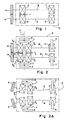
- the work rolls A comprise relatively narrow grooved discs mounted at the ends of the roll shafts B, with the shaft bearings C, D being arranged entirely on the inboard side of the rolls within a housing E.
- This mill configuration a major portion of the rolling load is absorbed by the bearings D located nearest to the work rolls.
- This type of mill stand is highly advantageous in that it allows operating personnel to quickly replace worn or cracked work rolls without having to disturb the roll shafts and their bearings.
- small diameter work rolls are employed in order to maximise product elongation while minimising product spread.
- the diameters of the roll shafts and their bearings must also be decreased correspondingly.
- the rolling forces F on the work rolls A will combine with the reactive forces F cl F d of the bearings C, D to bow the shaft B.
- the shaft bows it undergoes both deflection accompanied by changes in slope.
- the term “deflection” refers to the lateral distance “x” that the shaft axis is shifted from its normal unstressed location
- the term “slope” refers to the angle “o” formed between a tangent to the bowed shaft and a line parallel to the unstressed shaft axis.
- the extent of shaft deflection "x” and the degree of shaft slope "o” will vary from point to point along the shaft. Shaft bowing imposes a practical limit on the permissible axial length "1" of the bearings, which combined with the limitations imposed on bearing diameters by the use of smaller work rolls, limits the capacity of the mill to handle heavy rolling loads.
- overhung mill stands have been employed mostly in finishing trains, where the rolling loads are relatively light in comparison to the rolling loads in the roughing and intermediate trains.
- the primary objective of the present invention is to achieve a significant increase in the rolling capacity of an overhung rolling mill stand, while avoiding the above-described disadvantages and drawbacks of the prior art.
- the overhung rolling mill stand of the present invention may be described as also having work rolls A mounted at the ends of roll shafts B.
- the opposite ends of the roll shafts are rotatably supported by first bearings C, whereas tandem pairs of second bearings D a , D b are arranged adjacent to and on the inboard side of the work rolls.
- the bearings are again enclosed within a housing E.
- the tandem second bearings are mounted on carrier members F which in turn are mounted on supports G.
- the first bearings C are supported by carrier members H.
- This system provides for independent self adjusting movement between the second tandem bearings D a , D b and their respective carrier members F, between the carrier members F and their respective supports G, and between the first bearings C and their respective carrier members H. All of these self adjusting movements occur about parallel axes which extend transversely with respect to the axes of the roll shafts B. Means are provided for simultaneously adjusting the supports G and the carrier members H associated with each shaft in opposite directions relative to the mill pass line in order to adjust the parting between the work rolls A.
- tandem second bearings D a , D b undergo self adjusting movements relative to their respective carrier members F, and the first bearings C undergo similar self adjusting movements relative to their respective carrier members H.
- the carrier members F undergo self adjusting movements relative to their supports G.
- the net result is that the second tandem bearings freely accommodate both shaft deflection and changes in shaft slope, while the first bearings C freely accommodate changes in shaft slope (there being no shaft deflection at these points).
- the carrier members F are adjustable about axes contained in a reference plane P l , and plane P I is preferably located with respect to the tandem second bearings D a , D b so as to distribute the rolling load equally therebetween.
- tandem second bearings D a , D b can freely accommodate changes in both shaft deflection and slope, their combined axial lengths l a , l b can be made to exceed the axial lengths 1 of the single bearings D, with the results that the rolling capacity of the mill can be increased by as much as 90% as compared with conventional arrangements of the type shown in Figure 1. This advantage is realised without resorting to the backup rolls or outboard bearings which characterise prior art attempts at increasing rolling capacity.
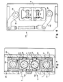
- an overhung mill stand in accordance with the present invention comprising a housing E closed at its front and rear ends respectively by housing plates 12 and 14.
- Roll shafts B are contained within the housing E. Ends of the shafts B protrude through the front housing plate 12 to receive work rolls A. Although not shown, it will be understood that the work rolls are removably mounted on the shaft ends by means well known to those skilled in the art.
- the roll shafts B are rotatably supported at locations adjacent to their opposite ends by first bearings C. Tandem second bearings D a , D b rotatably support the roll shafts at locations adjacent to and directly inboard of the work rolls A.
- the bearings C, D a and D b are preferably of the sleeve type, each having a cylindrical bushing 16 surrounding a cylindrical shaft portion. Such bearings are ideally suited for the high rotational speeds encountered in modern day finishing mills, which currently have the ability to finish roll steel rod products at speeds on the order of 100 meters/sec.
- the bushings 16 of the tandem second bearings D a , D b are contained in separate bearing chocks 18.
- the chocks 18 are provided with externally protruding cylindrically convex bosses 20 which are slidably received in cylindrical concavities in the inner surfaces of associated carrier members F.
- the exterior surfaces of the carrier members in turn are provided with cylindrically convex bosses 22 which are slidably received in cylindrical concavities in the inner surface of associated saddle-type supports G.
- the supports G are externally configured to be carried on first eccentrics 24 formed on roll parting adjustment shafts 26.
- the roll parting adjustment shafts 26 extend in parallel relationship with the roll shafts B, their ends being journalled for rotation in the front and rear housing plates 12, 14.
- the axis a l of shafts 26 are oppositely offset by equal distances from a reference plane P 2 containing the roll shaft axes, with the eccentric centers a 2 being contained in the plane P 2'
- the chocks 18 are appropriately drilled to receive connecting bolts 28 and compression springs 30.
- the springs 30 resiliently urge the chocks apart and thus ensure that the above-described bosses remain rotatably seated in their respective concavities.
- the bushings 16 of the first bearings C are contained in their own chocks 32.
- the chocks 32 have laterally protruding trunnions 34 received in openings in carrier members H.
- the carrier members H are in turn secured to collars 38 in which are journalled second eccentrics 40 on the roll parting adjustment shafts 26.
- the rear ends of the roll parting adjustment shafts 26 protrude through the rear housing plate 14. As can best be seen in Figure 4, these rearwardly protruding shaft ends are mechanically interconnected by means of levers 42 and a turnbuckle link assembly 44. Initial adjustment of the turnbuckle link assembly 44 will cause the roll parting adjustment shafts 26 and their eccentrics 24, 40 to rotate in opposite directions until they differ in phase by 180 0 , thereby centralising the parting between the work rolls A before operational installation.
- Roll parting adjustment is obtained by simultaneously rotating the shafts 26 in the same directions. This may be achieved by any convenient means, such as for example a removable crank 45 (see Figure 3) engageable with the exposed front end of the upper shaft 26. As the shafts 26 rotate in the same direction, their eccentrics 24, 40 will cooperate respectively with the saddle supports F and the collars 38 to shift the roll shafts B towards or away from one another.
- the roll shafts B are axially located by means of thrust bearings 46 surrounding reduced diameter shaft end extensions 47.
- the thrust bearings are retained in the chocks 32. by means of end caps 48, the latter being detachably fixed to brackets on the housing rear plate 14 by means of cross pins 50.
- the roll shafts B each carry gears 52 which mesh with gears 54 on parallel intermediate drive shafts 56.
- the gears 54 are intermeshed, and one of the intermediate drive shafts 56 is driven by conventional means (not shown).
- lubricating oil is applied liberally to the shaft bearings as well as to their adjustable supports and the roll parting adjustment mechanisms.
- the components employed to supply the lubricating oil, as well as the seals used to contain the oil in the housing and to exclude contaminants such as cooling water and mill scale, are all well known to those skilled in the art. Consequently, in the interest of simplicity, these components and seals have not been illustrated in the drawings.
- each of the tandem second bearings D , D b is free to self adjust its position relative to its respective carrier member F, and because the carrier members F are also free to rotatably self adjust their positions relative to their respective supports G, the bearings D a , D b will readily accommodate both changes in shaft deflection and slope.
- the tandem second bearings D a , D b are each slidably adjustable relative to their respective carrier members F about axes A3 lying on and extending transversely across the rotational axes of the roll shafts B.
- the carrier members F are slidably adjustable relative to their respective supports E about axes a4 contained in the reference plane P 1 .
- each tandem bearing can be made to carry approximately an equal portion of the rolling load. This positioning will be approximately mid-way between the bearings D a , D b .
- the cooperative engagement of the trunnions 34 with the carrier members H allows the first bearings C to accommodate changes in shaft slope by rotating about axes a 5 .
- the axes a3, a4 and a 5 are parallel.
- the manner of providing relative self adjusting movement between the tandem bearings D a , D b and the carrier members F, as well as between the carrier members F and their supports G, is not limited to that described previously.
- the interfaces between the chocks 18 and the carrier F and between the carrier and the support G by curved surfaces having different radii. This provides rolling contact at 58 as well as at 60, yet still afford captive relationships between the chocks 18, carrier member F and support G.
- the separate bearings 16 each absorb approximately an equal share of the load
- the carrier F is rotatably adjustable about an axis which extends transversely with respect to that of the shaft B and approximately midway between the separate bearings
- the separate bearings are each rotatable relative to the carrier about axes parallel to the rotatable carrier axis.
- tandem bearings D a , D b provide a significant increase in rolling capacity on the order of 90%.
- the inboard location of the tandem bearings does not interfere with removal and replacement of worn or cracked work rolls.
- the tandem bearings are enclosed by the housing E and thus are protected from contamination by cooling water, mill scale, etc.
- the arrangement of the tandem bearings D a , D b and the bearings C readily accommodates symmetrical roll parting adjustments.
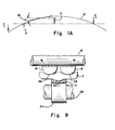
- rolls 62 may have their necks journalled in tandem sets of bearings 64a, 64b.
- the bearings of each tandem set are mounted for independent self adjusting movement on carrier members 66, which in turn are mounted for self adjusting movement on supports 68.
- the bearings will be free to accommodate both deflection and accompanying changes in slope of the rolls occasioned by the imposition of rolling loads.
- bearings D a , D b and C are described as being of the sleeve-type, other bearings including roller bearings might be employed. Other types of roll parting adjustment mechanism, drives, and housing designs are also possible.
Landscapes
- Engineering & Computer Science (AREA)
- General Engineering & Computer Science (AREA)
- Mechanical Engineering (AREA)
- Rolls And Other Rotary Bodies (AREA)
Applications Claiming Priority (2)
| Application Number | Priority Date | Filing Date | Title |
|---|---|---|---|
| US65695984A | 1984-10-02 | 1984-10-02 | |
| US656959 | 1991-02-15 |
Publications (2)
| Publication Number | Publication Date |
|---|---|
| EP0180326A2 true EP0180326A2 (fr) | 1986-05-07 |
| EP0180326A3 EP0180326A3 (fr) | 1987-05-20 |
Family
ID=24635297
Family Applications (1)
| Application Number | Title | Priority Date | Filing Date |
|---|---|---|---|
| EP85306911A Withdrawn EP0180326A3 (fr) | 1984-10-02 | 1985-09-27 | Cage de laminoir |
Country Status (2)
| Country | Link |
|---|---|
| EP (1) | EP0180326A3 (fr) |
| BR (1) | BR8504847A (fr) |
Cited By (1)
| Publication number | Priority date | Publication date | Assignee | Title |
|---|---|---|---|---|
| CN108582949A (zh) * | 2018-05-31 | 2018-09-28 | 长兴广仁无纺布有限公司 | 一种不易产生偏移的新型无纺布辊轴调节装置 |
Family Cites Families (12)
| Publication number | Priority date | Publication date | Assignee | Title |
|---|---|---|---|---|
| FR342570A (fr) * | 1903-08-24 | 1904-09-12 | Julius Albert Elsner | Procédé perfectionné pour l'enlèvement de la poussière des gardines, meubles, tapis et tissus de toute nature |
| DE421732C (de) * | 1924-04-29 | 1925-11-17 | Karl Peter Dr Ing | Lageranordnung fuer Walzwerke |
| DE432772C (de) * | 1924-11-18 | 1926-08-13 | Skf Svenska Kullagerfab Ab | Druckverteilungsvorrichtung fuer Lager |
| US1685751A (en) * | 1925-01-19 | 1928-09-25 | Allis Chalmers Mfg Co | Bearing |
| GB335120A (en) * | 1928-11-27 | 1930-09-18 | Rheinland Ag Maschf | Improvements in or relating to roller or ball bearings with divided bearing casings |
| GB330849A (fr) * | 1929-05-28 | 1930-06-19 | Aktiebolaget Svenska Kullagerfabriken | |
| DE667421C (de) * | 1937-12-12 | 1938-11-11 | Kugelfischer Erste Automatisch | Abstuetzung von Waelzlagergehaeusen |
| DE2216011A1 (de) * | 1972-04-01 | 1973-10-04 | Schloemann Ag | Drahtwalzgeruest mit fliegend gelagerten walzen |
| US4446712A (en) * | 1981-12-14 | 1984-05-08 | Southwire Company | Propped cantilevered roll stand |
| US4423612A (en) * | 1981-12-18 | 1984-01-03 | Southwire Company | Cantilevered roll shaft bearing bracket |
| US4457155A (en) * | 1982-03-03 | 1984-07-03 | White Consolidated Industries, Inc. | Overhung bar rolling mill stand and two-axis gauge control system |
| JPS58187616A (ja) * | 1982-04-24 | 1983-11-01 | Nippon Steel Corp | メタル軸受 |
-
1985
- 1985-09-27 EP EP85306911A patent/EP0180326A3/fr not_active Withdrawn
- 1985-10-01 BR BR8504847A patent/BR8504847A/pt unknown
Cited By (2)
| Publication number | Priority date | Publication date | Assignee | Title |
|---|---|---|---|---|
| CN108582949A (zh) * | 2018-05-31 | 2018-09-28 | 长兴广仁无纺布有限公司 | 一种不易产生偏移的新型无纺布辊轴调节装置 |
| CN108582949B (zh) * | 2018-05-31 | 2023-09-01 | 长兴广仁无纺布有限公司 | 一种不易产生偏移的新型无纺布辊轴调节装置 |
Also Published As
| Publication number | Publication date |
|---|---|
| BR8504847A (pt) | 1986-07-22 |
| EP0180326A3 (fr) | 1987-05-20 |
Similar Documents
| Publication | Publication Date | Title |
|---|---|---|
| EP0693327B1 (fr) | Réglage de profil pour laminoirs à cylindres multiples | |
| USRE28107E (en) | Rolling mill | |
| US3147648A (en) | Strip mill with roll cartridge | |
| SU1031719A1 (ru) | Устройство дл обкатывани винтовых поверхностей | |
| US4453393A (en) | Four high mill of the paired-roll-crossing type | |
| JPH04228205A (ja) | 特殊鋼圧延路と線材圧延路とを組み合わせた圧延装置 | |
| US4552007A (en) | Device for replacing the rolls of rolling stands | |
| JPS59199153A (ja) | ロ−ル式連鋳機 | |
| KR910005829B1 (ko) | 지지롤러를 사용하여 지지할 수 있는 작업롤을 가지는 압연스탠드 | |
| EP0180326A2 (fr) | Cage de laminoir | |
| US3318130A (en) | Backed mill with readily exchangeable working rolls | |
| US3543555A (en) | Form changing device for continuous casting | |
| US2949147A (en) | Roller leveler with driven backup rolls | |
| US4182149A (en) | Roll stand | |
| US5752404A (en) | Roll shifting system for rolling mills | |
| JPS608122B2 (ja) | ロ−ル交換装置 | |
| US5804134A (en) | Compact rolling block | |
| US3861190A (en) | Rolling mills | |
| US3718026A (en) | Cluster mill with cantilevered rolls | |
| US1864299A (en) | Rolling mill | |
| US3098403A (en) | Rolling mill structure | |
| MXPA97000189A (en) | Lamination block compa | |
| US1903724A (en) | Multihigh rolling mechanism | |
| EP0072385B1 (fr) | Laminoir à 4 cylindres du type à cylindres croisés | |
| GB2106022A (en) | Skew rolling mill for tubes |
Legal Events
| Date | Code | Title | Description |
|---|---|---|---|
| PUAI | Public reference made under article 153(3) epc to a published international application that has entered the european phase |
Free format text: ORIGINAL CODE: 0009012 |
|
| AK | Designated contracting states |
Kind code of ref document: A2 Designated state(s): DE FR GB IT SE |
|
| PUAL | Search report despatched |
Free format text: ORIGINAL CODE: 0009013 |
|
| AK | Designated contracting states |
Kind code of ref document: A3 Designated state(s): DE FR GB IT SE |
|
| STAA | Information on the status of an ep patent application or granted ep patent |
Free format text: STATUS: THE APPLICATION IS DEEMED TO BE WITHDRAWN |
|
| 18D | Application deemed to be withdrawn |
Effective date: 19871121 |
|
| RIN1 | Information on inventor provided before grant (corrected) |
Inventor name: WOODROW, HAROLD E. |