EP0180907A2 - Dispositif avertisseur dans un système de signalisation de risque - Google Patents
Dispositif avertisseur dans un système de signalisation de risque Download PDFInfo
- Publication number
- EP0180907A2 EP0180907A2 EP85113784A EP85113784A EP0180907A2 EP 0180907 A2 EP0180907 A2 EP 0180907A2 EP 85113784 A EP85113784 A EP 85113784A EP 85113784 A EP85113784 A EP 85113784A EP 0180907 A2 EP0180907 A2 EP 0180907A2
- Authority
- EP
- European Patent Office
- Prior art keywords
- sensor
- detector
- circuit
- voltage
- contacts
- Prior art date
- Legal status (The legal status is an assumption and is not a legal conclusion. Google has not performed a legal analysis and makes no representation as to the accuracy of the status listed.)
- Granted
Links
Images
Classifications
-
- G—PHYSICS
- G08—SIGNALLING
- G08B—SIGNALLING SYSTEMS, e.g. PERSONAL CALLING SYSTEMS; ORDER TELEGRAPHS; ALARM SYSTEMS
- G08B26/00—Alarm systems in which substations are interrogated in succession by a central station
- G08B26/005—Alarm systems in which substations are interrogated in succession by a central station with substations connected in series, e.g. cascade
Definitions
- the invention relates to a detector arrangement in a hazard alarm system, in particular a fire alarm system, according to the features of the preamble of claim 1.
- the detection is of great importance insofar as the detection should be reliable and, on the other hand, it should be inexpensive to manufacture.
- the number of electrical contacts and their load form an important aspect for the connection technology of the detectors in a hazard detection system.
- Conventional limit detectors generally use two contacts between the actual detector and its associated detector detection, via which all detectors of a detector line are connected in parallel between the wires of a two-wire line. A series connection of several detectors, each with two contacts, is also common.
- At least three contacts are required for analog detectors, i.e. detectors with sensors (sensors) that record analog measured values and transmit them to the control center.
- the sensor is supplied with energy via two contacts, while a third contact supplies a signal which is dependent on the measured variable.
- This signal is then processed in an electronic circuit, which can be arranged in the detector recording, so that the signal can be transmitted to the control center in an addressed manner via the two-wire line. Additional contacts can be provided to enable identification of the detector type, the connection of parallel displays or the setting of a detector address.
- the electronic circuit is integrated in the respective detector and actuates a switch which is activated in dependence on the measured value in order to interrupt or switch on a wire of the two-wire line while the other wire is connected.
- This known detector arrangement also requires at least three contacts between the actual detector and the detector detection.
- the object of the invention is therefore to provide a detector arrangement for a hazard alarm system which has a large number of analog value-measuring detectors, which allows both conventional limit value detectors or simple sensors (for example thermistor for heat detectors) and analog value-measuring sensors (for example for smoke detectors) few circuit and contact elements in the same detector connection.
- the detector arrangement according to the invention has a sensor circuit with a sensor, which forms the actual plug-in detector, and an electronic circuit arrangement in the detector detection, a socket circuit. These two circuits are connected to each other via only two contacts, so that an analog value measuring sensor with only two connection contacts is connected in the detector.
- the sensor circuit has a sensor which is connected to the two contacts with a capacitor connected in parallel to the sensor via a diode.
- a transistor is connected to the two contacts via a measuring resistor. This transistor is controlled by a measuring output of the sensor, so that the sensor voltage at the measuring point of the sensor generates a proportional measuring current.
- the detector arrangement according to the invention only requires two contacts for analog value measuring sensors. These are fritted with the operational voltage, for example the quiescent voltage of 20 volts, and with currents of several milliamperes, which increases the contact reliability. In the measuring phase, however, the sensor causes a current to flow in the microampere range, which thus allows considerable contact resistance. In this way it is possible to make the two contacts particularly robust and inexpensive.
- analog value measuring sensors can be implemented in the same construction and operated in the same detector recording as limit detectors. This standardization enables savings in both development and production as well as in assembly and maintenance.
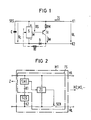
- the sensor S forms the measuring element or the measuring sensor, for example an optical scattered light sensor.
- the sensor S is connected to the connections (+) and (-) at a voltage of e.g. 20 volts operated via the connection contacts K1 and K2.
- the sensor circuit SES is connected via the connection contacts K1 and K2, as shown in FIG. 2, via a current measuring device SME to the detection line ML and is operated with the line voltage UL.
- the sensor voltage US proportional to the measured variable of the sensor is created. If necessary, the sensor S at the input T can be triggered via the resistor RT by the measuring voltage UM at the beginning of the measuring time MZ of an interrogation cycle AZ.
- the sensor voltage US is fed to the transistor TR and, via the measuring resistor RM, generates a measuring current IM which is proportional to the sensor voltage US and thus to the measured variable of the sensor S.
- the capacitor C lying parallel to the sensor S serves on the one hand as an energy store and on the other hand generates the increased current IS for fritting the contacts K1 and K2 during the idle time RZ during which the open-circuit voltage UR is applied.
- the sensor S and the capacitor C are in the sensor circuit SES the diode D connected to the contacts K1 and K2. If the detector arrangement according to the invention is operated in pulse detection technology, in which the individual detectors are connected in a chain to the detection line ML, the sensor circuit SES is arranged according to FIG. 2
- FIG. 2 shows an analog value detector M1 with the sensor circuit SES and the socket circuit FS.
- the circuit arrangement for the socket circuit is known in principle from German patent specification 2533382 controllable timer ZG, is located on the ML detection line. After the running time of the ZG timer, the switch SCH arranged in one wire of the ML signal line is actuated by it and switches the next analog detector (M2) to the detection line.
- the sensor circuit SES is connected to the signal line ML via the two contacts K1 and K2 via a current measuring device SME.
- the current measuring device SME controls the timing element ZG.
- the individual detectors M1 to Mi of a signaling line ML are cyclically queried from the central station Z for their respective analog detector measured value, the respective detector address being determined in the central station and the alarm or fault criteria in the central station from the individual detector measured values of the respective detector.
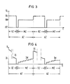
- a query cycle is composed of a long rest time RZ, a short start time SZ and a measurement time MZ as shown in the voltage and current diagram in FIGS. 3 and 4.
- the voltage diagram of the line voltage UL is shown in FIG. 3.
- the line voltage UL is, for example, 20 volts.
- the respective capacitors C of the sensor circuit SES are charged with this open-circuit voltage UR.
- the measurement of the individual analog values is started from the control center Z with the starting voltage US * 0 volt, the signal line being shadowed for the short time SZ.
- the measuring voltage UM which is lower than the rest voltage UR, is applied from the control center to the message line ML for the measuring time MZ.
- a new interrogation cycle AZ begins with the open circuit voltage UR.
- the sensor S is supplied with the voltage UC (UC #UR) from the storage capacitor C.
- UC #UR the voltage UC
- the diode D blocks the current flow between the sensor S or the sensor circuit SES and the signal line ML or the socket electronics FS.
- the line voltage UL is increased to the measuring voltage UM, e.g.
- a measuring current IM flows to the socket circuit, while the sensor S continues to be supplied with energy from the capacitor C.
- the capacitor C is dimensioned such that the capacitor voltage UC, even if it decreases by a few volts, always remains greater than the measuring voltage UM, so that the diode D is blocked.
- the line voltage UL is increased again from the measuring voltage UM to the open circuit voltage UR.
- the diode D becomes conductive and the sensor current IS increases by the supply current for the sensor S.
- FIG. 4 the corresponding current diagram of the line current IL is shown.
- the line current IL IM increases in a step-like manner, as is known per se, until a new interrogation cycle AZ begins, in which the line current IL suddenly increases to the sensor current IS.
- the process is repeated continuously with each interrogation cycle .
- the detector arrangement according to the invention can also be used for other transmission methods in addition to the embodiment described for the pulse detector technology. To do this, either at least two voltage levels must be generated in the circuit electronics of the detector, which can then be used in the manner described. Another possibility is to replace the diode with a switch which is replaced by a signal superimposed on the line voltage, e.g. a sound frequency signal, is controlled in a suitable manner.
Landscapes
- Business, Economics & Management (AREA)
- Emergency Management (AREA)
- Physics & Mathematics (AREA)
- General Physics & Mathematics (AREA)
- Fire Alarms (AREA)
- Aiming, Guidance, Guns With A Light Source, Armor, Camouflage, And Targets (AREA)
- Acyclic And Carbocyclic Compounds In Medicinal Compositions (AREA)
- Pharmaceuticals Containing Other Organic And Inorganic Compounds (AREA)
- Emergency Alarm Devices (AREA)
- Alarm Systems (AREA)
Priority Applications (1)
| Application Number | Priority Date | Filing Date | Title |
|---|---|---|---|
| AT85113784T ATE67878T1 (de) | 1984-10-31 | 1985-10-29 | Melderanordnung in einer gefahrenmeldeanlage. |
Applications Claiming Priority (2)
| Application Number | Priority Date | Filing Date | Title |
|---|---|---|---|
| DE3439895 | 1984-10-31 | ||
| DE3439895 | 1984-10-31 |
Publications (3)
| Publication Number | Publication Date |
|---|---|
| EP0180907A2 true EP0180907A2 (fr) | 1986-05-14 |
| EP0180907A3 EP0180907A3 (en) | 1988-07-20 |
| EP0180907B1 EP0180907B1 (fr) | 1991-09-25 |
Family
ID=6249209
Family Applications (1)
| Application Number | Title | Priority Date | Filing Date |
|---|---|---|---|
| EP85113784A Expired - Lifetime EP0180907B1 (fr) | 1984-10-31 | 1985-10-29 | Dispositif avertisseur dans un système de signalisation de risque |
Country Status (3)
| Country | Link |
|---|---|
| EP (1) | EP0180907B1 (fr) |
| AT (1) | ATE67878T1 (fr) |
| DE (1) | DE3584228D1 (fr) |
Family Cites Families (4)
| Publication number | Priority date | Publication date | Assignee | Title |
|---|---|---|---|---|
| DE1046761B (de) * | 1955-09-02 | 1958-12-18 | Ernst Fey Dipl Ing | Verfahren und Anordnung zur Verminderung des UEbergangswiderstandes von Kontakten in Messanordnungen |
| DE1254241B (de) * | 1965-02-08 | 1967-11-16 | Licentia Gmbh | Vorrichtung zur Sicherstellung einer gleichmaessig guten Kontaktgabe bei einer Anordnung zur Messstellenumschaltung |
| US4361833A (en) * | 1980-03-25 | 1982-11-30 | Monitran International, Inc. | Multi-sensor alarm system and method of protecting a premises |
| DE3225106C2 (de) * | 1982-07-05 | 1985-04-11 | Siemens AG, 1000 Berlin und 8000 München | Verfahren und Einrichtung zur automatischen Abfrage des Meldermeßwerts und der Melderkennung in einer Gefahrenmeldeanlage |
-
1985
- 1985-10-29 AT AT85113784T patent/ATE67878T1/de active
- 1985-10-29 EP EP85113784A patent/EP0180907B1/fr not_active Expired - Lifetime
- 1985-10-29 DE DE8585113784T patent/DE3584228D1/de not_active Expired - Lifetime
Also Published As
| Publication number | Publication date |
|---|---|
| EP0180907B1 (fr) | 1991-09-25 |
| DE3584228D1 (de) | 1991-10-31 |
| ATE67878T1 (de) | 1991-10-15 |
| EP0180907A3 (en) | 1988-07-20 |
Similar Documents
| Publication | Publication Date | Title |
|---|---|---|
| DE69231446T2 (de) | Intelligente lampe oder intelligenter kontakt für eine lampe | |
| DE2903041C2 (de) | Meldevorrichtung zur Überwachung des Auftretens von zu meldenden Ereignissen | |
| EP0067339A2 (fr) | Méthode et arrangement pour détecter des perturbations dans des systèmes de signalisation de risques, en particulier signalisation d'incendie | |
| EP0393233B1 (fr) | Système de transmission de signaux | |
| DE69033692T2 (de) | Feldinstrumentensystem | |
| DE3623705A1 (de) | Adressierbare schaltungsanordnung | |
| DE3428773A1 (de) | Ultraschallnaeherungsinitiator | |
| EP0098554B1 (fr) | Procédé et dispositif pour la demande automatique des valeurs de mesure de signalisation et de l'identificateur de signalisation dans une installation d'avertisseur d'alarme | |
| DE1964764A1 (de) | Alarmvorrichtung | |
| EP0180907B1 (fr) | Dispositif avertisseur dans un système de signalisation de risque | |
| EP1197936B2 (fr) | Système d'alarme | |
| EP0098552B1 (fr) | Procédé et dispositif pour la demande automatique des valeurs de mesure de signalisation et de l'identificateur de signalisation dans une installation d'avertisseur d'alarme | |
| EP0187317B1 (fr) | Appareil mesureur avec résistance à capteur de mesure | |
| DE3030252C2 (de) | Verfahren und Schaltungsanordnung zur Erfassung der Schaltzustände einer Vielzahl von peripheren Schaltern | |
| DE2719223C2 (de) | Anordnung zum Umsetzen von Alarmsignalen zwischen einem digitalen Nachrichtenübertragungssystem und einer zentralen Betriebsüberwachung | |
| DE3540434A1 (de) | Schaltungsanordnung zum abfragen des zustands wenigstens einer tasteinrichtung und liefern einer anzeige durch eine anzeigeeinrichtung | |
| EP0013706B1 (fr) | Dispositif pour la surveillance automatique de l'état de charge de la source d'alimentation indépendante du secteur et de l'humidité dans le répondeur d'un système de localisation de véhicules | |
| EP0177804B1 (fr) | Circuit d'alimentation en courant pour une tablette de numérisation | |
| EP0185175B1 (fr) | Procédé pour la transmission de l'identification des détecteurs dans un système de signalisation de risque | |
| DE2710046A1 (de) | Brandmeldesystem | |
| DE2145172C3 (de) | Fernübertragungseinrichtung für als digitale Impulstelegramme zu übertragende Informationen | |
| DE3225044C2 (de) | Verfahren und Einrichtung zur automatischen Abfrage des Meldermeßwerts und der Melderkennung in einer Gefahrenmeldeanlage | |
| DE2713280B2 (de) | Feuermeldeanlage mit mindestens einer zweidrähtigen Meldelinie für gleichspannungsversorgte Ionisationsfeuermelder | |
| DE2454196B2 (de) | Brandmelder | |
| DE2007398A1 (de) | Meldeanreizschaltung |
Legal Events
| Date | Code | Title | Description |
|---|---|---|---|
| PUAI | Public reference made under article 153(3) epc to a published international application that has entered the european phase |
Free format text: ORIGINAL CODE: 0009012 |
|
| AK | Designated contracting states |
Kind code of ref document: A2 Designated state(s): AT BE DE FR GB IT NL SE |
|
| PUAL | Search report despatched |
Free format text: ORIGINAL CODE: 0009013 |
|
| AK | Designated contracting states |
Kind code of ref document: A3 Designated state(s): AT BE DE FR GB IT NL SE |
|
| 17P | Request for examination filed |
Effective date: 19890109 |
|
| 17Q | First examination report despatched |
Effective date: 19901106 |
|
| GRAA | (expected) grant |
Free format text: ORIGINAL CODE: 0009210 |
|
| PGFP | Annual fee paid to national office [announced via postgrant information from national office to epo] |
Ref country code: AT Payment date: 19910918 Year of fee payment: 7 |
|
| AK | Designated contracting states |
Kind code of ref document: B1 Designated state(s): AT BE DE FR GB IT NL SE |
|
| PGFP | Annual fee paid to national office [announced via postgrant information from national office to epo] |
Ref country code: GB Payment date: 19910925 Year of fee payment: 7 |
|
| REF | Corresponds to: |
Ref document number: 67878 Country of ref document: AT Date of ref document: 19911015 Kind code of ref document: T |
|
| PGFP | Annual fee paid to national office [announced via postgrant information from national office to epo] |
Ref country code: SE Payment date: 19911017 Year of fee payment: 7 |
|
| PGFP | Annual fee paid to national office [announced via postgrant information from national office to epo] |
Ref country code: FR Payment date: 19911022 Year of fee payment: 7 |
|
| PGFP | Annual fee paid to national office [announced via postgrant information from national office to epo] |
Ref country code: BE Payment date: 19911023 Year of fee payment: 7 |
|
| PGFP | Annual fee paid to national office [announced via postgrant information from national office to epo] |
Ref country code: NL Payment date: 19911031 Year of fee payment: 7 |
|
| REF | Corresponds to: |
Ref document number: 3584228 Country of ref document: DE Date of ref document: 19911031 |
|
| ET | Fr: translation filed | ||
| PGFP | Annual fee paid to national office [announced via postgrant information from national office to epo] |
Ref country code: DE Payment date: 19911217 Year of fee payment: 7 |
|
| ITF | It: translation for a ep patent filed | ||
| GBT | Gb: translation of ep patent filed (gb section 77(6)(a)/1977) | ||
| PLBE | No opposition filed within time limit |
Free format text: ORIGINAL CODE: 0009261 |
|
| STAA | Information on the status of an ep patent application or granted ep patent |
Free format text: STATUS: NO OPPOSITION FILED WITHIN TIME LIMIT |
|
| 26N | No opposition filed | ||
| PG25 | Lapsed in a contracting state [announced via postgrant information from national office to epo] |
Ref country code: GB Effective date: 19921029 Ref country code: AT Effective date: 19921029 |
|
| PG25 | Lapsed in a contracting state [announced via postgrant information from national office to epo] |
Ref country code: SE Effective date: 19921030 |
|
| PG25 | Lapsed in a contracting state [announced via postgrant information from national office to epo] |
Ref country code: BE Effective date: 19921031 |
|
| BERE | Be: lapsed |
Owner name: SIEMENS A.G. Effective date: 19921031 |
|
| PG25 | Lapsed in a contracting state [announced via postgrant information from national office to epo] |
Ref country code: NL Effective date: 19930501 |
|
| NLV4 | Nl: lapsed or anulled due to non-payment of the annual fee | ||
| GBPC | Gb: european patent ceased through non-payment of renewal fee |
Effective date: 19921029 |
|
| PG25 | Lapsed in a contracting state [announced via postgrant information from national office to epo] |
Ref country code: FR Effective date: 19930630 |
|
| PG25 | Lapsed in a contracting state [announced via postgrant information from national office to epo] |
Ref country code: DE Effective date: 19930701 |
|
| REG | Reference to a national code |
Ref country code: FR Ref legal event code: ST |
|
| EUG | Se: european patent has lapsed |
Ref document number: 85113784.4 Effective date: 19930510 |