EP0185175B1 - Procédé pour la transmission de l'identification des détecteurs dans un système de signalisation de risque - Google Patents
Procédé pour la transmission de l'identification des détecteurs dans un système de signalisation de risque Download PDFInfo
- Publication number
- EP0185175B1 EP0185175B1 EP85113785A EP85113785A EP0185175B1 EP 0185175 B1 EP0185175 B1 EP 0185175B1 EP 85113785 A EP85113785 A EP 85113785A EP 85113785 A EP85113785 A EP 85113785A EP 0185175 B1 EP0185175 B1 EP 0185175B1
- Authority
- EP
- European Patent Office
- Prior art keywords
- voltage
- detector
- identification
- detectors
- sensor
- Prior art date
- Legal status (The legal status is an assumption and is not a legal conclusion. Google has not performed a legal analysis and makes no representation as to the accuracy of the status listed.)
- Expired - Lifetime
Links
Images


Classifications
-
- G—PHYSICS
- G08—SIGNALLING
- G08B—SIGNALLING SYSTEMS, e.g. PERSONAL CALLING SYSTEMS; ORDER TELEGRAPHS; ALARM SYSTEMS
- G08B26/00—Alarm systems in which substations are interrogated in succession by a central station
- G08B26/005—Alarm systems in which substations are interrogated in succession by a central station with substations connected in series, e.g. cascade
Definitions
- the invention relates to a method for transmitting identifiers of analog value-measuring sensors in a hazard alarm system, in particular a fire alarm system according to the preamble of claim 1.
- Automatic alarm systems are often equipped with many different types of detectors. Different types of detectors can be connected to a signaling line, which operate according to different physical principles. It is often necessary to treat messages from different detector types differently. For example, manually operated push button detectors can have higher priority than automatic fire detectors. Furthermore, different automatic fire detectors can be connected to one detection line, for example ionization smoke detectors, optical smoke detectors and heat detectors.
- sensors transmit their analog measured values with the detector address in analog or digital form to a signaling center, where they are processed, for example, by a microcomputer. If an additional detector identification is also transmitted, special optimized evaluation algorithms can be used for each detector type. In conventional limit value detection systems, detector detection usually takes place in that different detector types are connected to special evaluation modules via separate detector lines. With analog value transmitters Alarm systems are often set in the detector itself or in the detector acquisition next to the detector address, a detector identification, for example by a switch.
- various types of sensors for example ionization smoke sensors, optical smoke sensors and heat sensors
- predeterminable time intervals are carried out by the control center from tag polling cycles with a reduced quiescent voltage or with a reduced measuring voltage.
- the identifier of the respective detector is determined from the measured detector values which occur, which change according to the detector type in a defined manner compared to the measured values during the regular query, and are stored in a memory for the relevant detector for further processing.
- the detector arrangement ie the sensor circuit with different types of sensors, does not require any additional components.
- the identification takes place through a defined change in the measured values as a result of a change in the line voltage controlled by the signaling center.
- an ionization smoke detector can be changed by an identification interrogation cycle with a changed quiescent voltage, e.g. with a reduced open-circuit voltage compared to the normal open-circuit voltage, the analog measured value changing by a defined amount compared to the analog measured value during regular polling cycles.
- a heat or push button detector can be determined from the analog measured values changed by a certain amount compared to the regular polling cycles.
- An optical smoke detector can be determined from the combination of the two identification query cycles, that is to say one with a changed open-circuit voltage and the other time with a changed measurement voltage. This is possible because optical smoke sensors have a voltage regulator in a manner known per se and are therefore supplied with a constant voltage.
- FIG. 1 shows a sensor circuit with only two contacts K1 and K2.
- This current IM which is proportional to the analog measured value of the sensor, controls the running time of a timing element ZG via a current measuring device SME, as shown in FIG. 2.
- the idle voltage UR is present at terminals K1 and K2.
- the capacitor C charges up to the voltage UR via the contacts K1 and K2 and the diode D, so that UC is UR.
- the capacitor C serves as an energy store for the sensor S, which is connected via the diode D to the two contacts K1 and K2.
- the capacitor C is dimensioned in such a way that its current consumption during the start time SZ and the measurement time MZ, in which it is decoupled from the detection line ML by the diode D, is only slightly discharged. The sensor S is therefore operated with the voltage UR.
- the sensor voltage US present at the measuring point M of the sensor S is converted into a current IM proportional to the measured value via the transistor TR and the measuring resistor RM.
- the measuring voltage UM for the measuring phase with the measuring time MZ is then applied from the control center to the signaling line.
- a new interrogation cycle AZ then begins with the open circuit voltage UR.
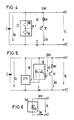
- the ionization smoke sensor SI has a measuring chamber MK and a reference chamber RK.
- the ionization smoke sensor SI is continuously supplied with voltage via the capacitor C.
- the sensor voltage US is present a proportional measuring current IM results via the transistor TR and the resistor RM. If smoke penetrates into the measuring chamber MK, the sensor voltage US and thus the measuring current IM change.
- the measuring current IM can also be influenced by a change in the open-circuit voltage UR. If the open-circuit voltage UR is changed, for example reduced, in such a sensor type, this sensor type can be distinguished from other sensor types by the measurement current change defined thereby.
- FIG. 5 where a sensor circuit with an optical smoke sensor SO is shown.
- the optical smoke sensor SO is supplied with a constant voltage UK, which the voltage regulator SPR supplies.
- the capacitor C is dimensioned such that it never discharges below the measuring voltage UM during operation.
- the constant voltage UK is stabilized accordingly low.
- the sensor voltage US can only be changed by smoke, but not by changing the line voltage UL.
- a change in the quiescent voltage UR and a change in the measuring voltage UM therefore do not change the analog measured value.
- an optical smoke detector ORM
- ORM optical smoke detector
- the result is a relative one simple sensor circuit, as shown in FIG. 6 using the example of a heat detector WM.
- the heat sensor SW is a temperature-dependent resistor RV, which is connected directly to the terminals K1 and K2 and through which the measuring current IM flows.
- the measuring current IM depends both on the resistance value and on the applied voltage UL.
- FIG. 7 shows the voltage diagram of the line voltage UL for several (n-1 to / m + 3) query cycles.
- the detector detection can be queried, for example, when the signaling system is started up, or operationally at certain time intervals, for example daily.
- a regular interrogation cycle AZ can be followed by an identification interrogation cycle KAZ1 with reduced idle voltage UR2, this in turn by a regular interrogation cycle AZ and then another identification interrogation cycle KAZ2 with reduced measurement voltage UM2.
- (n-1) is a regular interrogation cycle AZ in which the normal idle voltage UR1 is applied for the idle time RZ.
- the measuring phase then takes place with the regular measuring voltage UM1 for the measuring time MZ.
- a first identification polling cycle KAZ1 (n) is carried out with a reduced quiescent voltage UR2.
- the subsequent interrogation cycle (n + 1) is again a regular cycle with the open circuit voltage UR1 and the measurement voltage UM1.
- the measuring voltage UM is changed, reduced from the value UM1 to the value UM2.
- This query cycle KAZ2 detects detectors whose measured value depends on the measuring voltage UM2, for example heat and push button detectors. Detectors whose measured values are independent of the line voltage, i.e. not dependent on the open circuit voltage UR or on the measuring voltage UM, do not provide any measured value changes during the two identification query cycles KAZ1 and KAZ2, so that, for example, optical smoke detectors can be recognized.
- the next measurement cycle (n + 3) is again a regular interrogation cycle AZ with the open circuit voltage UR 1 and the measurement voltage UM1.
Landscapes
- Business, Economics & Management (AREA)
- Emergency Management (AREA)
- Physics & Mathematics (AREA)
- General Physics & Mathematics (AREA)
- Fire Alarms (AREA)
- Fire-Detection Mechanisms (AREA)
- Radio Relay Systems (AREA)
- Selective Calling Equipment (AREA)
Claims (7)
- Procédé pour la transmission d'identifications de capteurs mesurant des valeurs analogiques dans des installations de signalisation de danger, notamment des installations d'avertissement d'incendie, comportant un central (Z) possédant plusieurs lignes de signalisation (ML), auxquelles est raccordée respectivement une multiplicité (i) de transmetteurs (M1...Mi) de différents types, qui sont alimentés à partir du central (Z) avec une tension de repos (UR1) et dont les valeurs analogiques de mesure sont interrogées cycliquement pour l'obtention de critères d'alarme ou de perturbation avec une tension de mesure (UM1) qui diffère de la tension de repos (UR1), et selon lequel chaque cycle d'interrogation (SZ) est constitué par une durée de repos (RZ), une durée de démarrage (SZ) brève par rapport à la durée de repos et une durée de mesure (MZ), et selon lequel chaque transmetteur (M1...) comprend un circuit de détection (SES) comportant un capteur (S), et un circuit (FS) placé dans la monture, ces circuits étant raccordés galvaniquement entre eux par l'intermédiaire d'un couple de contacts (K1 et K2),
caractérisé par le fait que pour identifier les transmetteurs (M1,...) de différents types, les cycles d'interrogation d'identification (KAZ1 ou KAZ2) sont exécutés à des intervalles de temps pouvant être prédéterminés, à partir du central (Z), avec une tension de repos (UR2) modifiée ou avec une tension de mesure (UM2) modifiée, auquel cas, l'identification du transmetteur respectif (M1,...) est déterminée à partir des valeurs de mesure obtenues des transmetteurs et étant mémorisée pour le transmetteur considéré dans une mémoire. - Procédé suivant la revendication 1, caractérisé par le fait que des détecteurs de fumée à ionisation (IRM) sont déterminés avec les cycles d'interrogation d'identification (KAZ1) exécutés avec une tension de repos (UR2) modifiée, à partir des valeurs analogiques de mesure des transmetteurs, qui sont modifiées d'une valeur déterminée par rapport à des cycles réguliers d'interrogation (AZ).
- Procédé suivant la revendication 1, caractérisé par le fait que des détecteurs de chaleur ou des transmetteurs à boutons-poussoirs sont déterminés avec les cycles d'interrogation d'identification (KAZ2) exécutés avec une tension de mesure (UM2) modifiée, à partir des valeurs analogiques de mesure des transmetteurs, modifiés d'une valeur déterminée par rapport à des cycles réguliers d'interrogation.
- Procédé suivant les revendications 2 et 3, caractérisé par le fait que des détecteurs optiques de fumée (ORM) sont déterminés avec les cycles d'interrogation d'identification (KAZ1) exécutés avec une tension de repos (UR2) modifiée et avec les cycles d'interrogation d'identification (KAZ2) exécutés avec une tension de mesure (UM2) modifiée, à partir des valeurs analogiques de mesure des transmetteurs, non modifiées, qui apparaissent, des détecteurs optiques de fumée possédant de façon connue en soi un régulateur de tension (SPR).
- Procédé suivant l'une des revendications précédentes, caractérisé par le fait que plusieurs cycles d'interrogation d'identification (KAZ1 et KAZ2) sont exécutés une fois chaque jour.
- Procédé suivant l'une des revendications précédentes, caractérisé par le fait qu'après chaque cycle régulier d'interrogation (AZ), un cycle d'interrogation d'identification (KAZ1 ou KAZ2) est exécuté alternativement avec une tension de repos (UR2) modifiée et avec une tension de mesure (UM2) modifiée.
- Procédé suivant l'une des revendications précédentes, caractérisé par le fait que pour l'interrogation d'identification, on réduit la tension de repos ou la tension de mesure.
Priority Applications (1)
| Application Number | Priority Date | Filing Date | Title |
|---|---|---|---|
| AT85113785T ATE67045T1 (de) | 1984-10-31 | 1985-10-29 | Verfahren zur kennungsuebertragung von sensoren in einer gefahrenmeldanlage. |
Applications Claiming Priority (2)
| Application Number | Priority Date | Filing Date | Title |
|---|---|---|---|
| DE3439856 | 1984-10-31 | ||
| DE3439856 | 1984-10-31 |
Publications (3)
| Publication Number | Publication Date |
|---|---|
| EP0185175A2 EP0185175A2 (fr) | 1986-06-25 |
| EP0185175A3 EP0185175A3 (en) | 1988-07-27 |
| EP0185175B1 true EP0185175B1 (fr) | 1991-09-04 |
Family
ID=6249195
Family Applications (1)
| Application Number | Title | Priority Date | Filing Date |
|---|---|---|---|
| EP85113785A Expired - Lifetime EP0185175B1 (fr) | 1984-10-31 | 1985-10-29 | Procédé pour la transmission de l'identification des détecteurs dans un système de signalisation de risque |
Country Status (3)
| Country | Link |
|---|---|
| EP (1) | EP0185175B1 (fr) |
| AT (1) | ATE67045T1 (fr) |
| DE (1) | DE3584000D1 (fr) |
Families Citing this family (1)
| Publication number | Priority date | Publication date | Assignee | Title |
|---|---|---|---|---|
| EP0254125B1 (fr) * | 1986-07-10 | 1991-02-13 | Siemens Aktiengesellschaft | Système de signalisation de dangers |
Family Cites Families (2)
| Publication number | Priority date | Publication date | Assignee | Title |
|---|---|---|---|---|
| US4361833A (en) * | 1980-03-25 | 1982-11-30 | Monitran International, Inc. | Multi-sensor alarm system and method of protecting a premises |
| DE3225106C2 (de) * | 1982-07-05 | 1985-04-11 | Siemens AG, 1000 Berlin und 8000 München | Verfahren und Einrichtung zur automatischen Abfrage des Meldermeßwerts und der Melderkennung in einer Gefahrenmeldeanlage |
-
1985
- 1985-10-29 EP EP85113785A patent/EP0185175B1/fr not_active Expired - Lifetime
- 1985-10-29 DE DE8585113785T patent/DE3584000D1/de not_active Expired - Lifetime
- 1985-10-29 AT AT85113785T patent/ATE67045T1/de not_active IP Right Cessation
Also Published As
| Publication number | Publication date |
|---|---|
| ATE67045T1 (de) | 1991-09-15 |
| EP0185175A3 (en) | 1988-07-27 |
| EP0185175A2 (fr) | 1986-06-25 |
| DE3584000D1 (de) | 1991-10-10 |
Similar Documents
| Publication | Publication Date | Title |
|---|---|---|
| DE4036639C2 (fr) | ||
| EP0067339B1 (fr) | Méthode et arrangement pour détecter des perturbations dans des systèmes de signalisation de risques, en particulier signalisation d'incendie | |
| EP0248298B1 (fr) | Dispositif détecteur de danger | |
| EP0418322A1 (fr) | Agencement d'adressage. | |
| EP0042501B1 (fr) | Dispositif pour la transmission des valeurs mesurées dans un système d'avertissement d'incendie | |
| DE2533382B1 (de) | Verfahren und Einrichtung zur UEbertragung von Messwerten in einem Brandmeldesystem | |
| EP0418409B1 (fr) | Procédé et dispositif pour éviter les influences climatiques de l'environnement sur les indicateurs automatiques d'incendie | |
| DE3207993A1 (de) | Zweiweg-gegenverkehrs-feuermelder | |
| DE2939462C2 (de) | Verfahren und Einrichtung zur Identifizierung einzelner Melder in Einbruch- oder Brandmeldeanlagen | |
| EP0052220B1 (fr) | Méthode et dispositif de mesure de résistance dans une ligne de signalisation | |
| DE3225106C2 (de) | Verfahren und Einrichtung zur automatischen Abfrage des Meldermeßwerts und der Melderkennung in einer Gefahrenmeldeanlage | |
| EP0098554B1 (fr) | Procédé et dispositif pour la demande automatique des valeurs de mesure de signalisation et de l'identificateur de signalisation dans une installation d'avertisseur d'alarme | |
| EP0185175A2 (fr) | Procédé pour la transmission de l'identification des détecteurs dans un système de signalisation de risque | |
| EP0254125B1 (fr) | Système de signalisation de dangers | |
| DE3424294A1 (de) | Abfrageeinrichtung zur identifikation der stellung von schaltern | |
| EP0362797B2 (fr) | Procédé pour un fonctionnement économique en énergie de détecteurs de danger dans un dispositif de détection de danger | |
| EP0125485A1 (fr) | Aménagement de circuits pour supprimer des signaux dans des détecteurs de fumée | |
| EP0213383B1 (fr) | Méthode et dispositif de surveillance du fonctionnement de détecteurs optiques de fumée | |
| DE3225032C2 (de) | Verfahren und Einrichtung zur wahlweisen automatischen Abfrage der Melderkennung oder des Meldermeßwerts in einer Gefahrenmeldeanlage | |
| EP0098553B1 (fr) | Procédé et dispositif pour la demande automatique des valeurs de mesure de signalisation et/ou de l'identificateur de signalisation dans une installation d'avertisseur d'alarme | |
| EP0212045A2 (fr) | Adaptation d'un dispositif d'affichage ou d'évaluation à un capteur | |
| EP0013706B1 (fr) | Dispositif pour la surveillance automatique de l'état de charge de la source d'alimentation indépendante du secteur et de l'humidité dans le répondeur d'un système de localisation de véhicules | |
| EP0180907B1 (fr) | Dispositif avertisseur dans un système de signalisation de risque | |
| DE102005053439B4 (de) | Verbrauchswerterfassungssystem und Verfahren zum Betreiben eines Verbrauchswerterfassungssystems | |
| EP0362798B1 (fr) | Procédé pour un fonctionnement économique en énergie de détecteurs de danger dans un dispositif de détection de danger |
Legal Events
| Date | Code | Title | Description |
|---|---|---|---|
| PUAI | Public reference made under article 153(3) epc to a published international application that has entered the european phase |
Free format text: ORIGINAL CODE: 0009012 |
|
| AK | Designated contracting states |
Kind code of ref document: A2 Designated state(s): AT BE DE FR GB IT NL SE |
|
| PUAL | Search report despatched |
Free format text: ORIGINAL CODE: 0009013 |
|
| AK | Designated contracting states |
Kind code of ref document: A3 Designated state(s): AT BE DE FR GB IT NL SE |
|
| 17P | Request for examination filed |
Effective date: 19890109 |
|
| 17Q | First examination report despatched |
Effective date: 19901106 |
|
| GRAA | (expected) grant |
Free format text: ORIGINAL CODE: 0009210 |
|
| AK | Designated contracting states |
Kind code of ref document: B1 Designated state(s): AT BE DE FR GB IT NL SE |
|
| REF | Corresponds to: |
Ref document number: 67045 Country of ref document: AT Date of ref document: 19910915 Kind code of ref document: T |
|
| PGFP | Annual fee paid to national office [announced via postgrant information from national office to epo] |
Ref country code: GB Payment date: 19910913 Year of fee payment: 7 |
|
| PGFP | Annual fee paid to national office [announced via postgrant information from national office to epo] |
Ref country code: AT Payment date: 19910918 Year of fee payment: 7 |
|
| REF | Corresponds to: |
Ref document number: 3584000 Country of ref document: DE Date of ref document: 19911010 |
|
| PGFP | Annual fee paid to national office [announced via postgrant information from national office to epo] |
Ref country code: SE Payment date: 19911017 Year of fee payment: 7 |
|
| PGFP | Annual fee paid to national office [announced via postgrant information from national office to epo] |
Ref country code: FR Payment date: 19911022 Year of fee payment: 7 |
|
| PGFP | Annual fee paid to national office [announced via postgrant information from national office to epo] |
Ref country code: BE Payment date: 19911023 Year of fee payment: 7 |
|
| PGFP | Annual fee paid to national office [announced via postgrant information from national office to epo] |
Ref country code: NL Payment date: 19911031 Year of fee payment: 7 |
|
| ET | Fr: translation filed | ||
| ITF | It: translation for a ep patent filed | ||
| GBT | Gb: translation of ep patent filed (gb section 77(6)(a)/1977) | ||
| PGFP | Annual fee paid to national office [announced via postgrant information from national office to epo] |
Ref country code: DE Payment date: 19911217 Year of fee payment: 7 |
|
| PLBE | No opposition filed within time limit |
Free format text: ORIGINAL CODE: 0009261 |
|
| STAA | Information on the status of an ep patent application or granted ep patent |
Free format text: STATUS: NO OPPOSITION FILED WITHIN TIME LIMIT |
|
| 26N | No opposition filed | ||
| PG25 | Lapsed in a contracting state [announced via postgrant information from national office to epo] |
Ref country code: GB Effective date: 19921029 Ref country code: AT Effective date: 19921029 |
|
| PG25 | Lapsed in a contracting state [announced via postgrant information from national office to epo] |
Ref country code: SE Effective date: 19921030 |
|
| PG25 | Lapsed in a contracting state [announced via postgrant information from national office to epo] |
Ref country code: BE Effective date: 19921031 |
|
| BERE | Be: lapsed |
Owner name: SIEMENS A.G. Effective date: 19921031 |
|
| PG25 | Lapsed in a contracting state [announced via postgrant information from national office to epo] |
Ref country code: NL Effective date: 19930501 |
|
| NLV4 | Nl: lapsed or anulled due to non-payment of the annual fee | ||
| GBPC | Gb: european patent ceased through non-payment of renewal fee |
Effective date: 19921029 |
|
| PG25 | Lapsed in a contracting state [announced via postgrant information from national office to epo] |
Ref country code: FR Effective date: 19930630 |
|
| PG25 | Lapsed in a contracting state [announced via postgrant information from national office to epo] |
Ref country code: DE Effective date: 19930701 |
|
| REG | Reference to a national code |
Ref country code: FR Ref legal event code: ST |
|
| EUG | Se: european patent has lapsed |
Ref document number: 85113785.1 Effective date: 19930510 |