EP0181459B1 - Appareil d'impression par jets d'encre - Google Patents
Appareil d'impression par jets d'encre Download PDFInfo
- Publication number
- EP0181459B1 EP0181459B1 EP85111450A EP85111450A EP0181459B1 EP 0181459 B1 EP0181459 B1 EP 0181459B1 EP 85111450 A EP85111450 A EP 85111450A EP 85111450 A EP85111450 A EP 85111450A EP 0181459 B1 EP0181459 B1 EP 0181459B1
- Authority
- EP
- European Patent Office
- Prior art keywords
- ink jet
- jet printing
- line
- ink
- printing apparatus
- Prior art date
- Legal status (The legal status is an assumption and is not a legal conclusion. Google has not performed a legal analysis and makes no representation as to the accuracy of the status listed.)
- Expired
Links
- 238000007641 inkjet printing Methods 0.000 title claims abstract description 43
- 238000007639 printing Methods 0.000 claims abstract description 50
- 230000005684 electric field Effects 0.000 claims abstract description 10
- 239000012858 resilient material Substances 0.000 claims description 2
- 239000000976 ink Substances 0.000 description 50
- 239000003086 colorant Substances 0.000 description 3
- 230000005284 excitation Effects 0.000 description 3
- 230000003252 repetitive effect Effects 0.000 description 3
- 238000010586 diagram Methods 0.000 description 2
- 241000510097 Megalonaias nervosa Species 0.000 description 1
- 230000003213 activating effect Effects 0.000 description 1
- 230000003111 delayed effect Effects 0.000 description 1
- 230000001419 dependent effect Effects 0.000 description 1
- 238000004519 manufacturing process Methods 0.000 description 1
- 238000000034 method Methods 0.000 description 1
- 230000009974 thixotropic effect Effects 0.000 description 1
Images

Classifications
-
- B—PERFORMING OPERATIONS; TRANSPORTING
- B41—PRINTING; LINING MACHINES; TYPEWRITERS; STAMPS
- B41J—TYPEWRITERS; SELECTIVE PRINTING MECHANISMS, i.e. MECHANISMS PRINTING OTHERWISE THAN FROM A FORME; CORRECTION OF TYPOGRAPHICAL ERRORS
- B41J2/00—Typewriters or selective printing mechanisms characterised by the printing or marking process for which they are designed
- B41J2/005—Typewriters or selective printing mechanisms characterised by the printing or marking process for which they are designed characterised by bringing liquid or particles selectively into contact with a printing material
- B41J2/01—Ink jet
- B41J2/07—Ink jet characterised by jet control
- B41J2/12—Ink jet characterised by jet control testing or correcting charge or deflection
Definitions
- the present invention relates to ink jet printing and deals more specifically with apparatus for vertically randomizing the flight path of an ink drop ejected from a printing means.
- Graphics particularly large-scale color graphics, such as outdoor advertising billboards and signs or displays used in large open areas such as shopping malls and airports, produced by an ink jet system are often not of high quality and have a corduroy texture or washboard appearance.
- One ink jet printing system for producing large-scale graphics moves a receiving surface relative to an ink jet printing station in a continuous, line scanning fashion to print a line.
- the printing station generally has a number of ink jet printing heads which may be arranged to print the same color for monochromatic graphics or which may be arranged to print a number of colors in a polychromatic halftone manner such as generally described in prior U.S. Patent No. 4,367,482 to produce polychromatic graphics.
- each printed line is really a horizontal band which is made up of a number of pixel areas arranged end-to-end and located sequentially along the scan line.
- Potential dot positions form an array of rows and columns identical for all pixel areas and each row of the array is associated with one printing head of a group of heads comprising the printing station.
- each printer head moves along a scan line it moves past a succession of points on the line in relation to each of which the printer head may (or may not) eject a relatively large volume drop of ink to apply dots of substantially fixed size onto the surface at the dot position.
- the printing station moves downwardly a distance equal to the height of the printed line and the next group of lines associated with the rows forming a pixel area is printed immediately adjacent to the previous group.
- a large number of such side-by-side printed lines form the desired sign or display.
- An ink drop printed at a dot position on the surface is not a uniform thickness due to the thixotropic properties and surface tension generally characterizing pigmented inks and exhibits density variations across its surface with the density being higher at the dot center than at its periphery. Consequently, a printed line may exhibit a lower density along its edges than at its center and the region or gap between adjacent printed lines may be lighter than the centers of the lines. The repetitive lighter gaps can produce a corduroy texture appearance in the completed graphic.
- the present invention resides in an ink jet printing apparatus for controlling the flight path of an ink drop ejected from an ink jet printing head.
- the printing head is operated in response to control means to selectively apply or not apply dots to a number of dot positions located sequentially along a line scanned by the printing head.
- the flight paths of ink drops ejected from a printing head are vertically randomized to print dots at positions randomly deviated vertically with respect to a line scanned by the printing head.
- a variable amplitude control means is coupled to a deflection voltage source means to produce a randomly varying intensity bipolar electric field in a vertical direction perpendicular to the line of flight to randomly deflect the ink drop flight path in a first and opposite direction respectively with respect to a line scanned by the printing head.
- a plurality of flat panels 12,12 collectively providing a receiving surface 14 move in an endless path edgewise and rectilinearly in succession past an ink jet printing station 16.
- the panels 12, 12 are moved on an endless carrier 18 supported by a track 20 and propelled by a power unit 22 located near the printing station 16.
- the printing station 16 includes a vertical column 20 for slideably supporting a carriage 26 for vertical movement relative to the column, the carriage 26 in turn supporting at least one ink jet head for printing ink dots of substantially fixed size onto the outwardly directed surface 14 of each panel 12 as it passes the printing station.
- each ink jet printing head of the printing station ejects ink drops onto the faces of the panels with the drops moving from the nozzle to a panel along a substantially horizontal line of flight, so that each time a panel passes the printing station the drops ejected by a printing head, if it is operating at that time, fall on a horizontal scan line.
- the vertical movement of the carriage 26 and of the carrier 18 is coordinated so that with each full revolution of the carrier about its endless path, the carriage 26 is moved downwardly by a given increment so that each time a panel passes the printing station each ink jet printing head of the printing station scans a line on the panel which is new to it.
- the operation of the ink jet printing heads and the movement of the carriage 26 is controlled by a controller such as, for example, a computer 32. Timing of the excitation of the printing heads is slaved to the motion of the carrier 18 and to a carrier position .encoder unit 34.-Graphics information controlling the excitation of the ink jet printing heads to cause each head to either print or not print a dot at each potential dot position on the surface of each panel maybe supplied to the controller 32 in various different ways. For example, it maybe in the form of preprocessed information recorded onto a magnetic tape 36 read by the controller.
- the graphics generating system of Fig. 1 generates polychromatic graphics and it is further assumed that the printing station 16 has twelve ink jet printing heads for printing four different colors used in the production of polychromatic halftone graphics, the colors being cyan, magenta, yellow and black.
- nozzles 46, 46 associated with the printing heads are arranged such that three heads print black, three print cyan, three print magenta and three print yellow.
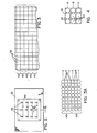
- the halftone printing process involves the use of square pixels measuring 0,254cm (one-tenth inch) on a side. The pixels are indicated generally at 38, 38 in Fig. 3 and are arranged in end-to-end successive side-by-side horizontal lines or bands 40, 40.
- each pixel 38 which is one-tenth of (2,54cm) 2 (an inch square), contains nine potential dot positions represented generally by the circles 42, 42, having centers 44, 44, the centers 44 therefore being spaced 0,084cm (0.033 inches) from one another along both horizontal and vertical lines.
- each pixel there are three horizontal lines, A, B and C each line containing three dot positions 42, 42.
- the three nozzles 46, 46 of each row D, E, F and G are vertically spaced from one another by a distance of 0,084cm (0.033 inches) so that as a receiving surface passes the printing station the three nozzles 46, 46 of a row such as the row D, if operated, print ink dots respectively along the three different lines A, B and C of the associated band 40 of pixels. That is, in each row, as viewed in Fig. 2, the left nozzle 46 may be the lowest one, the middle nozzle may be positioned 0,084cm (0.033 inches) above the left one, and the right nozzle may be the highest one positioned 0,084cm (0.033 inches) above the middle one.
- each dot position of a pixel is printed only if desired in accordance with the graphic information supplied to the controller 32.
- the horizontal spacing between the dot positions appearing on a line A, B or C is determined by the slaving of the printer head excitation to the movement of the carrier and such exitation is such that each time the carrier moves 0.033 inches relative to the printing station, a decision is made as to whether or not each printing head is to be actuated.
- each band 40 is made up of ink dots printed along three different lines A, B and C, the lines A, B and C representing the scanning lines of the associated ink jet printing heads and nozzles 46, 46.
- the pixel bands 40, 40 are only printed at potential dot positions along the lines A, B and C and lighter gaps 39, 39 appear from line-to-line due to the density variations of the dots printed along each line.
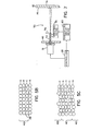
- the flight path of an ink drop ejected from one of the ink jet printing heads associated with printing the upper and/or lower lines of a pixel is vertically randomized with respect to its ink jet head scanning line to print either on and above and/or on and below the scanning line as illustrated in Figs. 5b and 5c.
- the ink drop flight path of the ink jet printing head associated with printing dots along one line is vertically randomized to print dots on, above or below line C with some of the dots being printed in the lighter gaps 39, 39 appearing above and below line C.
- the ink drop flight path associated with dots printing along line C is randomized to darken the lighter gaps 39, 39 above and below line C by overlapping some dots associated with line B above and some dots associated with line A below, a lighter gap 39 remains between line A and line B. It is preferable therefore, to vertically randomize the ink drop flight paths associated with printing all the lines to substantially eliminate the corduroy texture appearance that is produced by repetitive lighter gaps.
- the ink drop flight paths of the ink jet printing heads associated with printing dots along lines A, B and C are vertically randomized.
- the ink drop flight paths associated with printing dots along lines A, B and C are randomized to print on, above and below lines A, B and C respectively with some of the dots associated with line A overlapping some of the dots associated with line C above and line B below; and with some of the dots associated with line B overlapping some of the dots associated with line A above and line C below; and with some of the dots associated with line C overlapping some of the dots associated with line B above and line A below.
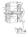
- FIG. 6 one embodiment of an ink jet printing apparatus for vertically randomizing an ink drop flight path is shown therein and is designated generally by the numeral 50.
- An ink jet head 51 is, as are all eleven other of the heads, shown generally mounted to a mounting plate 48 with its nozzle 46 extending through the plate and directed to the passing surface 14 of a panel 12 so that an ink drop ejected from the nozzle 46 moves from the nozzle to the surface 14 along a generally horizontal flight path 52 in the absence of any path deflection provided by the apparatus 50.
- the apparatus 50 includes charging electrodes 54 which electrodes are supplied with a charging voltage from a charging means 56 to electrostatically charge an ink drop passing between the electrodes.
- the charging means 56 generates a charging voltage in timed response to a signal received from a trigger means 58 which trigger means itself is responsive to information provided from the controller 32.
- Deflection plates 60 are connected to a deflection voltage source means 62 which source generates an electrical potential to create an electric field between the two plates to deflect an ink drop passing between the plates.
- the amount and direction of the ink drop deflection is dependent on the magnitude and direction of the electric field created between the deflection plates 60.
- the magnitude of the deflection voltage and accordingly the intensity of the electric field is controlled by a variable amplitude controller means 64 which controller means is in turn activated by a signal from the trigger means 58.
- the activating signal is delayed for an amount of time equal to the time it takes the ink drop to move from the ink jet head 51 to the deflection plates 60 so that the ink drop deflected is the ink drop associated with the dot position to be printed.
- variable amplitude controller means 64 causes the deflection voltage source means 62 to generate an electric potential of one polarity for producing a bipolar electric field having a direction to deflect an ink drop in one direction and an opposite polarity to deflect an ink drop in the opposite direction respectively with respect to an ink jet head scan line.
- the amount that an ink drop flight path is deflected is proportional to the magnitude of the electric potential applied to the deflection plates 60.
- the maximum potential supplied to the deflection plates 60 is predetermined to limit the ink drop flight path deflection to a maximum angle ALPHA as illustrated in Fig. 6a, above and below the horizontal flight path 52.
- a flight path deflection angle equal to or less than the maximum angle ALPHA corresponds to a dot being printed on the surface 14 within a maximum distance X above or below a dot printed with a horizontal flight path.
- Randomizing circuit means 63 within the variable amplitude controller means 64 causes the deflection voltage source means 62 to produce a randomly varying magnitude electric potential to create a bipolar electric field having a randomly varying intensity and direction so that charged ink drops passing through the plates 60 are deflected to print dots at positions randomly deviated vertically with respect to an ink jet scanning line.
- Such randomizing circuit means 63 might comprise, for example, a programmable variable resistance network connected in series with the deflection source means 62 to vary the magnitude of the electric potential supplied to the deflection plates 60 as the resistance is varied.
- the resistance is varied in accordance with a random number selected from a set of random numbers contained, for example, in a PROM look-up table and each number is represented by the presence or absence of a signal in each of the bit positions which comprise the number in a digital format.
- the magnitude can also be varied using a white noise generator or a digital pseudo random electric potential sequence generator.
- a polarity reversing means such as a switch is included in the circuit means 63 to cause the deflection source means output electric potential to randomly change polarity in response to the presence or absence of a signal in a predetermined bit position in a random number selected from the look-up table.
- ink jet printing apparatus for vertically randomizing an ink drop flight path is shown in another embodiment and is designated generally by the numeral 70.
- An ink jet head 51 of the type described above is, as are all eleven other of the heads in the printing station, shown generally mounted to a mounting plate 48 with its nozzle 72 extending through the plate and directed to the passing surface 14 of a panel 12 so that an ink drop ejected from the nozzle 72 moves from the nozzle to the surface along a generally horizontal flight path 74 in the absence of any path deflection provided by the apparatus 70.
- the nozzle 72 of the ink jet head 51 is comprised of a resilient material to permit nozzle movement.
- the nozzle 72 is coupled to a vibrating means 76 which causes the nozzle to move in a vertical direction indicated by direction arrow 78 generally perpendicular to the line of flight of an ink drop ejected from the nozzle.
- the vibrating means 76 might comprise, for example, a solenoid or a piezoelectric transducer.
- a randomizing circuit means 80 is driven by controller 32 to generate a randomly varying magnitude electric potential to drive the vibrating means 76 and the magnitude of nozzle movement is proportional to the magnitude of an electric potential applied to the vibrating means. Therefore, the nozzle movement is randomly varied by applying a randomly varying magnitude electric potential to the vibrating means to cause dots to be printed at positions randomly deviated vertically with respect to an ink jet scanning line.
Landscapes
- Particle Formation And Scattering Control In Inkjet Printers (AREA)
- Ink Jet (AREA)
Claims (10)
Priority Applications (1)
| Application Number | Priority Date | Filing Date | Title |
|---|---|---|---|
| AT85111450T ATE39089T1 (de) | 1984-11-14 | 1985-09-10 | Tintenstrahldrucker. |
Applications Claiming Priority (2)
| Application Number | Priority Date | Filing Date | Title |
|---|---|---|---|
| US06/671,291 US4575730A (en) | 1984-11-14 | 1984-11-14 | Ink jet printing randomizing droplet placement apparatus |
| US671291 | 2003-09-25 |
Publications (2)
| Publication Number | Publication Date |
|---|---|
| EP0181459A1 EP0181459A1 (fr) | 1986-05-21 |
| EP0181459B1 true EP0181459B1 (fr) | 1988-12-07 |
Family
ID=24693895
Family Applications (1)
| Application Number | Title | Priority Date | Filing Date |
|---|---|---|---|
| EP85111450A Expired EP0181459B1 (fr) | 1984-11-14 | 1985-09-10 | Appareil d'impression par jets d'encre |
Country Status (6)
| Country | Link |
|---|---|
| US (1) | US4575730A (fr) |
| EP (1) | EP0181459B1 (fr) |
| JP (1) | JPH0626888B2 (fr) |
| AT (1) | ATE39089T1 (fr) |
| CA (1) | CA1250783A (fr) |
| DE (1) | DE3566641D1 (fr) |
Families Citing this family (31)
| Publication number | Priority date | Publication date | Assignee | Title |
|---|---|---|---|---|
| US5367319A (en) * | 1985-05-01 | 1994-11-22 | Burlington Industries, Inc. | Security protection for important documents and papers |
| US4797687A (en) * | 1985-05-01 | 1989-01-10 | Burlington Industries, Inc. | Patterning effects with fluid jet applicator |
| US4849768A (en) * | 1985-05-01 | 1989-07-18 | Burlington Industries, Inc. | Printing random patterns with fluid jets |
| NL193362C (nl) * | 1988-04-26 | 1999-08-03 | Stork Digital Imaging Bv | Werkwijze en stuurketen voor een drukkop voor het selectief deponeren van inkt op een substraat. |
| DE69228409T2 (de) * | 1991-07-01 | 1999-08-19 | Eastman Kodak Co. | Verfahren und Vorrichtung für die Abtastung eines Aufzeichnungsträgers |
| US5291214A (en) * | 1991-07-01 | 1994-03-01 | Eastman Kodak Company | Method and apparatus for scanning a receiving medium |
| DE69226827T2 (de) * | 1991-07-01 | 1999-01-14 | Eastman Kodak Co., Rochester, N.Y. | Verfahren und Vorrichtung für die Abtastung eines Aufzeichnungsträgers |
| JPH0531920A (ja) * | 1991-08-01 | 1993-02-09 | Canon Inc | インクジエツト記録装置 |
| JPH07112302B2 (ja) * | 1992-09-14 | 1995-11-29 | エスエムケイ株式会社 | リモ−トコントロ−ルシステムの送受信方式 |
| US5519415A (en) * | 1993-04-30 | 1996-05-21 | Hewlett-Packard Company | Encoder-signal timing uncertainty adjusted to improve esthetic quality in bidirectional inkjet printing |
| EP0622230A3 (fr) * | 1993-04-30 | 1995-07-05 | Hewlett Packard Co | Méthode d'impression bi-directionnelle. |
| US5894985A (en) * | 1995-09-25 | 1999-04-20 | Rapid Analysis Development Company | Jet soldering system and method |
| US6276589B1 (en) | 1995-09-25 | 2001-08-21 | Speedline Technologies, Inc. | Jet soldering system and method |
| US6186192B1 (en) | 1995-09-25 | 2001-02-13 | Rapid Analysis And Development Company | Jet soldering system and method |
| US5868305A (en) * | 1995-09-25 | 1999-02-09 | Mpm Corporation | Jet soldering system and method |
| US5894980A (en) * | 1995-09-25 | 1999-04-20 | Rapid Analysis Development Comapny | Jet soldering system and method |
| US5938102A (en) * | 1995-09-25 | 1999-08-17 | Muntz; Eric Phillip | High speed jet soldering system |
| US5937145A (en) * | 1997-06-09 | 1999-08-10 | Hewlett-Packard Company | Method and apparatus for improving ink-jet print quality using a jittered print mode |
| US6360044B1 (en) * | 1998-03-16 | 2002-03-19 | Corning Cable Systems Llc | Optical article printing for controlled attenuation |
| JP2001232859A (ja) * | 2000-02-21 | 2001-08-28 | Seiko Epson Corp | 印刷ヘッドの機械的な振動を考慮した双方向印刷 |
| US6318832B1 (en) | 2000-03-24 | 2001-11-20 | Lexmark International, Inc. | High resolution printing |
| US7008128B1 (en) * | 2000-07-27 | 2006-03-07 | Tadayoshi Nakanishi | System, method and apparatus for printing oversized print media |
| TW491772B (en) * | 2001-02-27 | 2002-06-21 | Acer Peripherals Inc | Device and method for improving the printing quality |
| JP4023331B2 (ja) * | 2002-06-03 | 2007-12-19 | ソニー株式会社 | 液体吐出装置及び液体吐出方法 |
| JP4506070B2 (ja) * | 2002-11-01 | 2010-07-21 | コニカミノルタホールディングス株式会社 | 防眩層の形成方法、防眩フィルムの製造方法及び防眩層形成用のインクジェット装置 |
| US7275807B2 (en) * | 2002-11-27 | 2007-10-02 | Edc Biosystems, Inc. | Wave guide with isolated coupling interface |
| JP4061644B2 (ja) * | 2002-12-12 | 2008-03-19 | ソニー株式会社 | 液体吐出装置及び液体吐出方法 |
| US7222927B2 (en) * | 2002-12-12 | 2007-05-29 | Sony Corporation | Liquid discharge device and liquid discharge method |
| JP3770252B2 (ja) | 2003-02-27 | 2006-04-26 | ソニー株式会社 | 液体吐出装置及び液体吐出方法 |
| JP4643162B2 (ja) * | 2004-03-25 | 2011-03-02 | ブラザー工業株式会社 | インクジェットヘッドの制御装置、インクジェットヘッドの制御方法、及びインクジェット記録装置 |
| KR101128746B1 (ko) * | 2007-05-22 | 2012-03-23 | 가부시키가이샤 알박 | 스페이서의 배치 방법 |
Family Cites Families (15)
| Publication number | Priority date | Publication date | Assignee | Title |
|---|---|---|---|---|
| CH551871A (fr) * | 1972-09-12 | 1974-07-31 | Paillard Sa | Procede d'ecriture par jet d'encre et dispositif pour sa mise en oeuvre. |
| US3864692A (en) * | 1973-09-26 | 1975-02-04 | Ibm | Time dependent deflection control for ink jet printer |
| US3898671A (en) * | 1973-12-12 | 1975-08-05 | Teletype Corp | Ink jet recording |
| JPS5517590A (en) * | 1978-07-27 | 1980-02-07 | Seiko Epson Corp | Ink jetting apparatus |
| JPS5847992B2 (ja) * | 1979-05-14 | 1983-10-26 | 株式会社リコー | インクジエツトプロツタ− |
| JPS5848353B2 (ja) * | 1979-05-14 | 1983-10-27 | 株式会社リコー | インクジエツトプロツタ− |
| DE2943018C3 (de) * | 1979-10-24 | 1982-05-13 | Siemens AG, 1000 Berlin und 8000 München | Verfahren und Anordnung zum Darstellen eines Halbtonbilds |
| US4281331A (en) * | 1980-01-24 | 1981-07-28 | Dennison Manufacturing Company | Variable rate ink jet printing |
| JPS56150565A (en) * | 1980-04-24 | 1981-11-21 | Sharp Corp | Forming method for dot row of ink jet printer |
| JPS5715978A (en) * | 1980-07-04 | 1982-01-27 | Fuji Xerox Co Ltd | Deflecting device of ink jet printer |
| JPS5720463A (en) * | 1980-07-14 | 1982-02-02 | Toshiba Corp | Semiconductor memory device |
| JPS57152958A (en) * | 1981-03-18 | 1982-09-21 | Nec Corp | Scanning on-demand ink jet printer |
| US4414583A (en) * | 1981-11-02 | 1983-11-08 | International Business Machines Corporation | Scanned light beam imaging method and apparatus |
| US4476542A (en) * | 1982-05-10 | 1984-10-09 | Xerox Corporation | Printing system |
| JPS58199166A (ja) * | 1982-05-17 | 1983-11-19 | Canon Inc | ドット式記録方法 |
-
1984
- 1984-11-14 US US06/671,291 patent/US4575730A/en not_active Expired - Lifetime
-
1985
- 1985-05-22 JP JP60110088A patent/JPH0626888B2/ja not_active Expired - Lifetime
- 1985-09-10 EP EP85111450A patent/EP0181459B1/fr not_active Expired
- 1985-09-10 AT AT85111450T patent/ATE39089T1/de not_active IP Right Cessation
- 1985-09-10 DE DE8585111450T patent/DE3566641D1/de not_active Expired
- 1985-09-16 CA CA000490850A patent/CA1250783A/fr not_active Expired
Also Published As
| Publication number | Publication date |
|---|---|
| ATE39089T1 (de) | 1988-12-15 |
| CA1250783A (fr) | 1989-03-07 |
| DE3566641D1 (en) | 1989-01-12 |
| JPS61120765A (ja) | 1986-06-07 |
| JPH0626888B2 (ja) | 1994-04-13 |
| EP0181459A1 (fr) | 1986-05-21 |
| US4575730A (en) | 1986-03-11 |
Similar Documents
| Publication | Publication Date | Title |
|---|---|---|
| US4575730A (en) | Ink jet printing randomizing droplet placement apparatus | |
| US4680596A (en) | Method and apparatus for controlling ink-jet color printing heads | |
| US5079571A (en) | Interlaced printing using spaced print arrays | |
| US4075636A (en) | Bi-directional dot matrix printer with slant control | |
| US4613871A (en) | Guard drops in an ink jet printer | |
| EP0633139A1 (fr) | Procédé d'impression entrelacée | |
| EP0458650A2 (fr) | Procédé et appareil pour l'impression multicolore entrelacée | |
| EP0816103A2 (fr) | Méthode d'impression à encre liquide | |
| US4596990A (en) | Multi-jet single head ink jet printer | |
| GB2031343A (en) | Skewed ink jet printer with overlapping print lines | |
| US4622561A (en) | Image forming method for dot matrix printer | |
| EP0497614B1 (fr) | Méthode pour l'impression entrelaçée à grande vitesse selon l'axe de balayage de la tête d'impression | |
| US5007748A (en) | Printer for bar code using thin and thick bar code fonts | |
| US6315388B1 (en) | Draft printing | |
| EP0677390A1 (fr) | Procédé pour perfectionner l'impression d'images graphiques et appareil d'impression à jet d'encre correspondant | |
| US3959797A (en) | Ink jet printer apparatus and method of printing | |
| US4638373A (en) | Method and apparatus for improving gray scale resolution in an ink jet printing system | |
| CA1205677A (fr) | Imprimante multivitesse | |
| CA2071323C (fr) | Appareil et procede d'impression graphique grande dimension | |
| EP0723870B1 (fr) | Impression d'images à échelles de gris par un réseau de jets d'encre à haute résolution | |
| JP4617571B2 (ja) | マルチノズルインクジェット記録装置 | |
| EP0170136B1 (fr) | Méthode et appareil de contrôle pour têtes d'impression multicolore à jet d'encre | |
| JPS59190862A (ja) | 中間調カラ−記録方式 | |
| US4368475A (en) | Jet drop copier | |
| US4538162A (en) | Method and apparatus for line-at-a-time printing |
Legal Events
| Date | Code | Title | Description |
|---|---|---|---|
| PUAI | Public reference made under article 153(3) epc to a published international application that has entered the european phase |
Free format text: ORIGINAL CODE: 0009012 |
|
| AK | Designated contracting states |
Kind code of ref document: A1 Designated state(s): AT BE CH DE FR GB IT LI LU NL SE |
|
| 17P | Request for examination filed |
Effective date: 19860807 |
|
| RAP1 | Party data changed (applicant data changed or rights of an application transferred) |
Owner name: METROMEDIA COMPANY |
|
| 17Q | First examination report despatched |
Effective date: 19880226 |
|
| GRAA | (expected) grant |
Free format text: ORIGINAL CODE: 0009210 |
|
| AK | Designated contracting states |
Kind code of ref document: B1 Designated state(s): AT BE CH DE FR GB IT LI LU NL SE |
|
| REF | Corresponds to: |
Ref document number: 39089 Country of ref document: AT Date of ref document: 19881215 Kind code of ref document: T |
|
| REF | Corresponds to: |
Ref document number: 3566641 Country of ref document: DE Date of ref document: 19890112 |
|
| ET | Fr: translation filed | ||
| ITF | It: translation for a ep patent filed | ||
| PG25 | Lapsed in a contracting state [announced via postgrant information from national office to epo] |
Ref country code: LU Free format text: LAPSE BECAUSE OF NON-PAYMENT OF DUE FEES Effective date: 19890930 |
|
| PLBE | No opposition filed within time limit |
Free format text: ORIGINAL CODE: 0009261 |
|
| STAA | Information on the status of an ep patent application or granted ep patent |
Free format text: STATUS: NO OPPOSITION FILED WITHIN TIME LIMIT |
|
| 26N | No opposition filed | ||
| PGFP | Annual fee paid to national office [announced via postgrant information from national office to epo] |
Ref country code: FR Payment date: 19900816 Year of fee payment: 6 |
|
| PGFP | Annual fee paid to national office [announced via postgrant information from national office to epo] |
Ref country code: DE Payment date: 19900818 Year of fee payment: 6 |
|
| PGFP | Annual fee paid to national office [announced via postgrant information from national office to epo] |
Ref country code: GB Payment date: 19900820 Year of fee payment: 6 Ref country code: CH Payment date: 19900820 Year of fee payment: 6 |
|
| PGFP | Annual fee paid to national office [announced via postgrant information from national office to epo] |
Ref country code: SE Payment date: 19900821 Year of fee payment: 6 Ref country code: BE Payment date: 19900821 Year of fee payment: 6 |
|
| PGFP | Annual fee paid to national office [announced via postgrant information from national office to epo] |
Ref country code: AT Payment date: 19900828 Year of fee payment: 6 |
|
| PGFP | Annual fee paid to national office [announced via postgrant information from national office to epo] |
Ref country code: LU Payment date: 19900830 Year of fee payment: 6 |
|
| ITTA | It: last paid annual fee | ||
| PGFP | Annual fee paid to national office [announced via postgrant information from national office to epo] |
Ref country code: NL Payment date: 19900930 Year of fee payment: 6 |
|
| PG25 | Lapsed in a contracting state [announced via postgrant information from national office to epo] |
Ref country code: GB Effective date: 19910910 Ref country code: AT Effective date: 19910910 |
|
| PG25 | Lapsed in a contracting state [announced via postgrant information from national office to epo] |
Ref country code: SE Effective date: 19910911 |
|
| PG25 | Lapsed in a contracting state [announced via postgrant information from national office to epo] |
Ref country code: LI Effective date: 19910930 Ref country code: CH Effective date: 19910930 Ref country code: BE Effective date: 19910930 |
|
| BERE | Be: lapsed |
Owner name: METROMEDIA CY Effective date: 19910930 |
|
| PG25 | Lapsed in a contracting state [announced via postgrant information from national office to epo] |
Ref country code: NL Effective date: 19920401 |
|
| GBPC | Gb: european patent ceased through non-payment of renewal fee | ||
| NLV4 | Nl: lapsed or anulled due to non-payment of the annual fee | ||
| PG25 | Lapsed in a contracting state [announced via postgrant information from national office to epo] |
Ref country code: FR Effective date: 19920529 |
|
| REG | Reference to a national code |
Ref country code: CH Ref legal event code: PL |
|
| PG25 | Lapsed in a contracting state [announced via postgrant information from national office to epo] |
Ref country code: DE Effective date: 19920602 |
|
| REG | Reference to a national code |
Ref country code: FR Ref legal event code: ST |
|
| EUG | Se: european patent has lapsed |
Ref document number: 85111450.4 Effective date: 19920408 |