EP0181569A2 - Flüssigbrennstoffzelle - Google Patents
Flüssigbrennstoffzelle Download PDFInfo
- Publication number
- EP0181569A2 EP0181569A2 EP85113834A EP85113834A EP0181569A2 EP 0181569 A2 EP0181569 A2 EP 0181569A2 EP 85113834 A EP85113834 A EP 85113834A EP 85113834 A EP85113834 A EP 85113834A EP 0181569 A2 EP0181569 A2 EP 0181569A2
- Authority
- EP
- European Patent Office
- Prior art keywords
- fuel
- water
- mixture
- tank
- circulation system
- Prior art date
- Legal status (The legal status is an assumption and is not a legal conclusion. Google has not performed a legal analysis and makes no representation as to the accuracy of the status listed.)
- Granted
Links
Images


Classifications
-
- H—ELECTRICITY
- H01—ELECTRIC ELEMENTS
- H01M—PROCESSES OR MEANS, e.g. BATTERIES, FOR THE DIRECT CONVERSION OF CHEMICAL ENERGY INTO ELECTRICAL ENERGY
- H01M8/00—Fuel cells; Manufacture thereof
- H01M8/04—Auxiliary arrangements, e.g. for control of pressure or for circulation of fluids
- H01M8/04082—Arrangements for control of reactant parameters, e.g. pressure or concentration
- H01M8/04186—Arrangements for control of reactant parameters, e.g. pressure or concentration of liquid-charged or electrolyte-charged reactants
-
- H—ELECTRICITY
- H01—ELECTRIC ELEMENTS
- H01M—PROCESSES OR MEANS, e.g. BATTERIES, FOR THE DIRECT CONVERSION OF CHEMICAL ENERGY INTO ELECTRICAL ENERGY
- H01M2300/00—Electrolytes
- H01M2300/0002—Aqueous electrolytes
- H01M2300/0005—Acid electrolytes
- H01M2300/0011—Sulfuric acid-based
-
- H—ELECTRICITY
- H01—ELECTRIC ELEMENTS
- H01M—PROCESSES OR MEANS, e.g. BATTERIES, FOR THE DIRECT CONVERSION OF CHEMICAL ENERGY INTO ELECTRICAL ENERGY
- H01M8/00—Fuel cells; Manufacture thereof
- H01M8/04—Auxiliary arrangements, e.g. for control of pressure or for circulation of fluids
- H01M8/04082—Arrangements for control of reactant parameters, e.g. pressure or concentration
- H01M8/04089—Arrangements for control of reactant parameters, e.g. pressure or concentration of gaseous reactants
- H01M8/04119—Arrangements for control of reactant parameters, e.g. pressure or concentration of gaseous reactants with simultaneous supply or evacuation of electrolyte; Humidifying or dehumidifying
-
- H—ELECTRICITY
- H01—ELECTRIC ELEMENTS
- H01M—PROCESSES OR MEANS, e.g. BATTERIES, FOR THE DIRECT CONVERSION OF CHEMICAL ENERGY INTO ELECTRICAL ENERGY
- H01M8/00—Fuel cells; Manufacture thereof
- H01M8/04—Auxiliary arrangements, e.g. for control of pressure or for circulation of fluids
- H01M8/04082—Arrangements for control of reactant parameters, e.g. pressure or concentration
- H01M8/04186—Arrangements for control of reactant parameters, e.g. pressure or concentration of liquid-charged or electrolyte-charged reactants
- H01M8/04194—Concentration measuring cells
-
- Y—GENERAL TAGGING OF NEW TECHNOLOGICAL DEVELOPMENTS; GENERAL TAGGING OF CROSS-SECTIONAL TECHNOLOGIES SPANNING OVER SEVERAL SECTIONS OF THE IPC; TECHNICAL SUBJECTS COVERED BY FORMER USPC CROSS-REFERENCE ART COLLECTIONS [XRACs] AND DIGESTS
- Y02—TECHNOLOGIES OR APPLICATIONS FOR MITIGATION OR ADAPTATION AGAINST CLIMATE CHANGE
- Y02E—REDUCTION OF GREENHOUSE GAS [GHG] EMISSIONS, RELATED TO ENERGY GENERATION, TRANSMISSION OR DISTRIBUTION
- Y02E60/00—Enabling technologies; Technologies with a potential or indirect contribution to GHG emissions mitigation
- Y02E60/30—Hydrogen technology
- Y02E60/50—Fuel cells
Definitions
- This invention relates to a liquid fuel cell, and particularly to a liquid fuel cell capable of stable operation for a prolonged time under controlled supply of fuel and water.
- the fuel cell 1 comprises a fuel electrode 2-1, an oxidizing agent electrode 2-2 counterposed to the fuel electrode 2-1 (the oxidizing agent electrode can be called “oxygen electrode” when oxygen is used as an oxidizing agent, or “air electrode” when air is used as an oxidizing agent), an electrolyte chamber provided between the oxidizing agent electrode 2-2 and the fuel electrode 2-1, a fuel chamber 4 provided adjacent to the fuel electrode 2-1, and an oxidizing agent chamber 5 provided adjacent to the oxidizing agent electrode 2-2.
- numeral 6 shows the fuel (which may contain water), or a mixture of fuel and electrolyte and also shows its flow direction
- numeral 7 likewise shows the oxidizing agent and also shows its flow direction.
- the fuel cell as structured above works as follows.
- the fuel 6 is supplied to the fuel chamber 4 and when the oxidizing agent 7 is supplied to the oxidizing chamber 5, the fuel 6 permeates into the fuel electrode 2-1 to generate electrons through the electrochemical reaction.
- a load is given to the external circuit, a direct current can be obtained.
- a product 81 is formed in the fuel chamber 4.
- the product is a carbon dioxide gas or carbonate when the fuel is methanol, formic acid or formalin, and nitrogen when the fuel is hydrazine.
- the supply of fuel 6 of a circulating type the product contains excess fuel or electrolyte, and it is necessary to separate and vent the gaseous product from the circulation system.
- the oxidizing agent 7 when the oxidizing agent 7 is supplied to the oxidizing agent chamber 5, the oxidizing agent 7 permeates and diffuses into the oxidizing agent electrode 2-2 to consume electrons through the electrochemical reaction.
- the electrolyte is of an acid type, a product 82 is formed.
- the product is mainly water and contains excess air.
- the electrolyte is of a base type, water is formed at the fuel electrode 2-1.
- the aqueous solution of electrolyte such as sulfuric acid or potassium hydroxide
- the aqueous solution leaks from the electrolyte chamber 3 and thoroughly permeates also into the electrodes, and a good cell performance can be obtained.
- the aqueous solution of electrolyte also leaks into the fuel chamber 4 in this case, and thus it is necessary to supply fuel mixture containing the aqueous solution of electrolyte prepared in advance as anolyte.
- the fuel chamber 4 is provided with a circulation system for supplying the fuel mixture to the fuel chamber 4 by a pump 9 and a system for supplying the fuel from a fuel tank 10 through a valve 11 to the circulation system, as shown in Fig. 2.
- the product gas 811 is vented from the circulation system after the passage through the fuel chamber 4, and the remaining mixture 812 is recycled to the fuel chamber.
- a fuel mixture in a constant mixing ratio prepared in advance is supplied to the circulating system from the single fuel tank 10 shown in Fig. 2.
- the consumption ratios of fuel and water in the circulation mixture 6 containing the fuel are not always constant, and depend on changes in load, changes in temperature of fuel cell during the operation, even though the load is constant, or changes in flow rate and temprature.or humidity of the air supplied as the oxidizing agent.
- the fuel supply system contains two essential components, i.e. fuel and water, and further may contain an electrolyte.
- these three components i.e. fuel, water and electrolyte are usually contained in the fuel supply system.
- these three components it is the fuel and water that are consumed.
- it is not necessary to take consumption of electrolyte into consideration.
- Consumption rate of fuel differs from that of water, because firstly water is always consumed at one electrode, whereas at another electrode water is always formed as a result of the electromotive reaction of a fuel cell, and formation of water at the fuel electrode or the oxidizing agent electrode, depends on the acidity or the alkalinity of electrolyte.
- the excess fuel that is not converted to the electric current at the fuel eelctrode migrates through the electrolyte chamber and permeates into the oxidizing agent electrode to occasion direct oxidation of the fuel, or water migrates as hydronium ions when the electrolyte ions migrate in the electrolyte chamber in the case of an acidic electrolyte.
- These phenomena also depend on the load current and operating temperature of a fuel cell.
- the amount of water carried by the oxidizing agent, for example, air by evaporation at the oxidizing agent electrode side depends on the feed rate, temperature and humidity of the oxidizing agent.
- the consumption rate of fuel differs from that of water on the grounds as described above, and thus the supply of a mixture of fuel and water only in a constant mixing ratio from a single tank to the fuel circulation system as shown in Fig. 2 can only meet a change in the amount of only one component among the two components, i.e. fuel and water, in the fuel circulation system including the fuel chamber. That is, adequate control over the fuel and water cannot be made, and stable and prolonged operation of a fuel cell is quite impossible to conduct. That is, the fuel in the fuel circulation system may be so concentrated that the heat is much generated or the current output is lowered, or the supply of fuel fails to catch up with the consumption, so that the fuel becomes short in the fuel circulation system.
- the cell voltage V shows a flat peak in a certain range of concentration C of fuel 6 when the current is constant.
- the fuel becomes short and m the cell voltage is lowered, whereas at a higher fuel concentration C , the excess fuel that fails to take part in the reaction at the fuel electrode 2-1 migrates through the electrolyte chamber 3 and permeates into the oxidizing agent electrode 2-2 to occasion direct combustion of fuel.
- the potential on the oxidizing agent electrode 2-2 is lowered with generation of heat, and consequently the cell voltage is lowered.
- the fuel concentration is too high or too low (e.g. less than C m1 or more than C m2 in Fig. 3)
- the ratio of the necessary amount of electrical energy-converted fuel to the amount of consumed fuel will be lowered, and thus the fuel ultization efficiency is considerably lowered.
- it is very important to select an appropriate fuel concentration.
- Japanese Patent Publication No. 48-31300 discloses that stable operation is possible at 1.5% by weight (0.5 moles/l), and if the concentration is less than 1.5% by weight, the voltage is lowered and the temperature is increased.
- the fuel concentration range for stable operation is about 0.3 moles/l as C m1 and about 2 moles/l as C m2 .
- the fuel concentration is very important in the fuel cell, and a more accurate apparatus for detecting or measuring the fuel concentration is still required.
- FIG. 4 A liquid fuel cell provided with an apparatus for detecting a fuel concentration now in practical use is shown in Fig. 4, where the same members as in Fig. 1 and Fig. 2 are indicated with the same reference numerals.
- a fuel supply system includes a system for circulating a mixture of fuel and an electrolyte solution (the mixture may be called "anolyte”) by a pump 9 and a system for supplying an appropriate amount of fuel to an anolyte tank 20 provided in the circulation system from a fuel tank 10 through a valve 17.
- the circulation system is open to the outside at an appropriate position to discharge the product gas 811.
- the fuel is supplied by opening the valve 17, and the opening or closure or control of the valve 17 is made by an apparatus 13 for detecting a fuel concentration provided in the anolyte tank 20 and a valve controller 171.
- the apparatus 13 for detecting a fuel concentration comprises an anode electrode 517 (which will be hereinafter referred to merely as “anode”), a cathode electrode 518 counterposed to the anode (the cathode electrode will be hereinafter referred to merely as “cathode”), a power source 519, and a detector 520.
- the anode 517 comprises a platinum plate 517a and a membrane 517b tightly laid on the platinum plate 517a by pressing.
- the concentration of methanol can be indeed determined by the apparatus with such a structure as described above, but its detection sensitivity is not better, as given below.
- Fig. 12 Relationship between the fuel concentration and detected electric current is shown in Fig. 12, where curve a shows those determined by an apparatus for detecting a fuel concentration using an anode with the membrane as shown in Fig. 5.
- the electric current changes with concentration C m but the change in electric current is small. That is, the detection sensitivity is poor.
- the adhesion between the platinum plate 517a and the membrane 517b (Fig. 5) is often inadequate, and the anolyte tends to stay therebetween, deteriorating the response to changes in the methanol concentration.
- a platinum-based catalyst layer is laid on the platinum plate 517a in place of the membrane 517b, much detected current can be obtained as shown by curve b in Fig. 12, but there is no change in the detected current in the practical range (about 0.3 - about 2 moles/i) and such a structure cannot be used as a sensor.
- Cyclic voltammetry using a reference electrode and an apparatus for detecting a fuel concentration by means of a small fuel cell as disclosed in Japanese Patent Application Kokai (Laid-open) No. 56-118273 are also available as another apparatus for detecting a fuel concentration.
- a reference electrode is required in addition to the detecting electrodes, and also a function generator and other devices are required, complicating the detecting system and deteriorating the reliability, the most important task of the sensor.
- An object of the present invention is to provide a liquid fuel with an improved supply of fuel and water to a fuel circulation system which can operate continuously and stably for a prolonged time in spite of differences in the consumption rates of fuel and water.
- Another object of the present invention is to provide a liquid fuel cell with an apparatus for detecting a fuel concentration with a high reliability and a high sensitivity in a simple structure.
- the present invention provides a liquid fuel cell having a circulation system for a fuel mixture comprising fuel and water, which comprises a first tank containing water or a water-rich fuel mixture comprising water and fuel, a second tank containing fuel or a fuel-rich mixture comprising water and fuel, a first detector for detecting the liquid level of the fuel mixture in the circulation system, a second detector for detecting a fuel concentration of the fuel mixture in the circulation system, or an output from the fuel cell, or a load current of the fuel cell, a valve means for controlling flow of the water or the water-rich mixture in the first tank to the circulation system in accordance with the output from the first detector, and a valve means for controlling flow of the fuel or the fuel-rich mixture in the second tank to the circulation system in accordance with the output from the second detector.
- an apparatus for detecting a fuel concentration by electrochemical reaction comprising an anode electrode provided with a fuel-controlling layer for controlling permeation of fuel through a catalyst layer, a cathode electrode, a power source and a detector, the anode electrode and the cathode electrode being dipped in the fuel mixture and a voltage being applied to the electrodes is used as a second detector in the present liquid fuel cell.
- the fuel concentration in the fuel circulation system is about 0.3 to about 2 moles/i, and the absolute amount of the fuel in the fuel circulation system is small.
- a fuel concentration sensor is used to detect the fuel concentration in the fuel circulation system to supply the fuel, or an output voltage or output current of the fuel cell is detected because the output voltage or current is reduced as the fuel concentration is lowered.
- a signal to open the valve to the fuel tank is emitted to supply the fuel to the fuel circulation system.
- a considerably large amount of water is present in the fuel circulation system, and thus it is preferable to supply the water to the fuel circulation system to checking whether a predetermined amount of water is retained in the fuel circulation system satisfactorily or not.
- a liquid level sensor is provided in the fuel circulation system of the fuel cell to detect whether the liquid level becomes lower than the standard level or not. When the liquid level is detected lower than the standard level, a signal to open the valve to the water tank is emitted to supply the water to the fuel circulation system.
- two tanks i.e. fuel tank and water tank, are provided, and only fuel is stored in the fuel tank and only water in the water tank.
- higher fuel concentration is locally and transiently developed in the fuel circulation system owing to the restricted circulation rate, unpreferably lowering the fuel utilization efficiency transiently.
- This problem can be solved by storing a fuel-rich mixture of fuel and water in the fuel tank.
- Preferable molar ratio of water to fuel in the fuel-rich mixture is 5 - 0 : 1, where zero means only fuel. It is preferable to select a ratio approximating to the ratio of consumption rate of water to that of fuel on average during the operation of the fuel cell.
- the problem can be solved by storing a water-rich mixture of fuel and water in the water tank.
- Preferable molar ratio of fuel to water in the water-rich mixture is 1 to 0 : 1, where zero means only water. It is preferable to select a ratio approximating to the fuel concentration in the fuel circulation system in the fuel cell.
- Electrodes 2 are each made from a porous carbon plate as a substrate and a catalyst of platinum-based substance supported on carbon powders, the catalyst being deposited on the substrate.
- a liquid mixture of methanol and dilute sulfuric acid which, of course, contains water, is circulated as an anolyte by a pump 9.
- a carbon dioxide gas is generated at the fuel electrode 2-1 as a product gas 811.
- Air is supplied to an oxidizing agent chamber 5 as an oxidizing agent 7, and the exhaust gas 82 contains formed water at the same time.
- a liquid level sensor 12 is provided on the liquid level corresponding to the liquid level threshold value near the upper end of the electrodes 2 in the fuel circulation system. When the liquid level is lowered, the sensor 12 works to emit a signal to open the valve 111 and supply the necessary amount of water from the water tank 101 to the fuel circulation system.
- a methanol concentration sensor 13 based on the electrochemical reaction is provided in the fuel circulation system and set to the methanol concentration of 1 mole/i.
- the sensor 13 works to emit a signal to open the valve 112 and supply the necessary amount of the fuel from the fuel tank 102 to the fuel circulation system.
- the valves may be pumps.
- the circulation rate of the anolyte in the fuel circulation system is set to 700 cc/min., and about 30 cc of water is supplied to the fuel circulation system from the water tank 101 with one opening of the valve 111 by the signal from the liquid level sensor 12 when the liquid level is lowered in the fuel circulation system.
- About 10 cc of fuel is supplied to the fuel circulation tank from the fuel tank 102 with one opening f the valve 112 by the signal from the methanol concentration sensor 13 when the fuel concentration becomes lower than 1 mole/i.
- the fuel concentration during the operation of liquid fuel cell is not necessarily 1 mole/i, and operation at a higher fuel concentration is possible, if the load current is relatively large, whereas the operation at a lower fuel concentration is also possible, if the load current is relatively small.
- the set electric current To set a fuel concentration, the set electric current must be changed, because the electric current is a function of fuel concentration according to the constant voltage system when the electrochemical reaction is utilized.
- a liquid fuel cell with two tanks i.e. a fuel tank containing only fuel and a water tank containing only water can be operated stably against fluctuations in load current, operating temperature or atmosphere.
- a water-rich fuel mixture is supplied from the water tank 101 in place of only water. That is, since the fuel concentration in the fuel circulation system is 1 mole/i, the water-rich fuel mixture in the water tank 101 is made to have a methanol concentration of 1 mole/A. That is, the molar ratio of methanol to water is about 0.02.
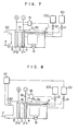
- a detector 15 to check an output voltage level is provided as shown in Fig. 7, and when a decrease in the output voltage level is detected, the valve 112 to the fuel tank 102 is opened with a signal from the detector 15 to supply the fuel to the fuel circulation system.
- a fuel-rich mixture of fuel and water is supplied from the fuel tank 102 in place of fuel only to suppress local and transient increase in the fuel concentration in the fuel circulation system.
- Molar ratio of water to methanol in the fuel-rich mixture in the fuel tank 102 is 2. In this case, total volume of the water and the fuel in both tanks is the same as in the embodiment of Fig. 6.
- both tanks 101 and 102 contain fuel mixtures, and local and transient unbalance of fuel concentration in the fuel circulation syutem can be largely improved, and thus the circulation rate by pump 9 through the fuel circulation system can be much reduced, and a good fuel cell performance can be obtained even at the reduced circulation rate of 200 cc/min.
- FIG. 8 Further embodiment of the present invention will be shown in Fig. 8, where only differences from the embodiment of Fig. 7 are that a signal for supplying a fuel-rich mixture from the fuel tank 102 to the fuel circulation system is emitted in accordance with a decrease in the load current of a liquid fuel cell.
- a detector 16 is connected to two end points of a resistor 18 at the fuel electrode 2-1 and the valve is opened with a signal from the detector 16, and further that a portion or all of water contained in the exhaust gas 82 from the oxidizing agent chamber 5 is recovered in a trap 17 and returned to the tank 101.
- the water recovery trap By the provision of the water recovery trap, the capacity of water tank 101 can be reduced.
- liquid fuel cells using methanol as fuel and an acidic electrolyte have been described, but the present invention is readily applicable also to an alkaline type liquid fuel cell using methanol as fuel, and other liquid fuel cells using hydrazine, formaldehyde, etc. as fuel by providing the fuel cell with two tanks and selecting fuel-water ratios of fuel mixtures in the tanks, as described above.
- an apparatus 516 for detecting a fuel concentration according to one embodiment of the present invention is schematically given, which comprises an anode 517, a cathode 518, a power source 519 and a detector 520, as in the prior art, but the anode 517 has a fuel-controlling layer 517b' through a catalyst layer 521 in the present invention.
- the fuel-controlling layer 517b' is prepared from a carbon fiber paper treated with a suspension of fine polytetrafluoroethylene particles by baking to give a controlled permeation and a strong water repellency to the paper.
- the fuel permeation can be adjusted to, for example, about 7 x 10 6 moles/cm 2 .min.mole/l by the treatment.
- a platinum-based catalyst layer 521 is provided on one side of the layer 517b' by kneading the catalyst with the same suspension of fine polytetrafluoroethylene particles as used above and applying the mixture to the one side of the layer 517b', followed by baking, thereby bonding the catalyst layer to the fuel-controlling layer. Then, the resulting integrated layers are tightly laid on an anode plate 517a made from, for example, tantalum to contact the catalyst layer with the anode plate 517a. It is preferable to fix the anode 517 to a frame serving also as a support for the anode so that the fuel can permeate from the fuel-controlling layer side.
- resin coats or pad plates of bakelite or glass are laid on all other sides than the fuel-controlling layer by an adhesive resin to form a seal layer (not shown in the drawings), thereby preventing all the other sides from direct contact with the anolyte.
- the electrode area is 4 cm 2
- the voltage is 0.9 volts
- the fuel permeation through the fuel-controlling layer 517b' is 1 x 10 -6 to 2 x 10 -5 mole/cm 2 ⁇ min ⁇ mole/l) and a fuel concentration is 0 to 1.5 moles/i
- the detected current has a good linearity and ⁇ a good sensitivity, shown by curve C in Fig. 12. That is, in the apparatus of Fig. 9, the catalyst layer 521 is provided between the anode 517a and the fuel-controlling layer 517b', and no liquid stagnation occurs therebetween, improving the permeation of the liquid, detection sensitivity and detection response.
- the fuel-controlling layer 517b' for use in the present invention is not only a fibrous carbon paper but can be also a porous carbon sheet, or can be an electroconductive porous material such as sintered metal. In that case, the fuel-controlling layer must have only a function to control the permeation of fuel, and thus an insulating sintered ceramics or organic porous materials can be also used.
- various other techniques such as coating, deposition, electrophoresis, CVD, etc. can be also used.
- a second fuel-controlling layer 517c is provided on the fuel-controlling layer 517b' at the cathode-facing side, where the second fuel-controlling layer 517c is prepared from a kneaded mixture of carbon powders or graphite fluoride powders with a suspension of fine polytetrafluoroethylene particles having a water repellency and an adhesiveness by applying the kneaded mixture to the surface of fuel-controlling layer 517b', followed by baking to integrate these two layers.
- Cathode 518. is prepared from a cathode plate 518a other than a platinum plate and a catalyst layer 518b laid on the cathode plate by deposition or by electrophoresis, and no special material is required for the cathode plate 518a. That is, a cathode with a good detection sensitivity can be obtained at a low cost.
- Fig. 11 other embodiment of the present invention is shown, where the cathode is improved by preparing a cathode 518 by laying a catalyst layer 518b on an electroconductive, porous material 518c and tightly laying the integrated porous material 518c and catalyst layer 518b on a cathode plate 518a.
- an electroconductive porous material carbon fiber paper or electroconductive polymer, sintered metal, etc. can be used to ensure the tight adhesion between the cathode plate 518a and the catalyst layer 518b.
- a liquid fuel cell can be stably and efficiently operated for a prolonged time in spite of different consumption rates of fuel and water even if the load current or operating temperature of the fuel cell or the temperature or humidity of the atmosphere is changed.
- an anode electrode having a fuel-controlling layer deposited thereon through a catalyst layer is used in the present apparatus for detecting a fuel concentration, and thus no liquid fuel stagnation occurs between the anode electrode and the fuel-controlling layer, improving the permeation of liquid fuel and activation of the reaction between the electrodes as well as improving the detection sensitivity and response and thus the reliability of the apparatus.
Landscapes
- Life Sciences & Earth Sciences (AREA)
- Engineering & Computer Science (AREA)
- Manufacturing & Machinery (AREA)
- Sustainable Development (AREA)
- Sustainable Energy (AREA)
- Chemical & Material Sciences (AREA)
- Chemical Kinetics & Catalysis (AREA)
- Electrochemistry (AREA)
- General Chemical & Material Sciences (AREA)
- Fuel Cell (AREA)
Applications Claiming Priority (4)
| Application Number | Priority Date | Filing Date | Title |
|---|---|---|---|
| JP229277/84 | 1984-10-31 | ||
| JP59229277A JPS61107666A (ja) | 1984-10-31 | 1984-10-31 | 液体燃料電池 |
| JP74264/85 | 1985-04-10 | ||
| JP60074264A JPH0626132B2 (ja) | 1985-04-10 | 1985-04-10 | 液体燃料電池の燃料濃度検出装置 |
Publications (3)
| Publication Number | Publication Date |
|---|---|
| EP0181569A2 true EP0181569A2 (de) | 1986-05-21 |
| EP0181569A3 EP0181569A3 (en) | 1986-12-30 |
| EP0181569B1 EP0181569B1 (de) | 1991-05-02 |
Family
ID=26415398
Family Applications (1)
| Application Number | Title | Priority Date | Filing Date |
|---|---|---|---|
| EP85113834A Expired - Lifetime EP0181569B1 (de) | 1984-10-31 | 1985-10-30 | Flüssigbrennstoffzelle |
Country Status (4)
| Country | Link |
|---|---|
| US (1) | US4629664A (de) |
| EP (1) | EP0181569B1 (de) |
| CA (1) | CA1257647A (de) |
| DE (1) | DE3582716D1 (de) |
Cited By (10)
| Publication number | Priority date | Publication date | Assignee | Title |
|---|---|---|---|---|
| WO2001023874A1 (de) * | 1999-09-24 | 2001-04-05 | Siemens Aktiengesellschaft | Bestimmung der alkoholkonzentration im elektrolyt von brennstoffzellen |
| DE10015334A1 (de) * | 2000-03-28 | 2001-10-04 | Volkswagen Ag | Vorrichtung zur Zuführung eines Brennstoffgemischs in eine Brennstoffzelle und entsprechendes Verfahren |
| WO2000026978A3 (de) * | 1998-11-03 | 2002-10-24 | Forschungszentrum Juelich Gmbh | Verfahren zur regelung der brennstoffkonzentration in einem alkohol oder ether als brennstoff und wasser enthaltenden brennstoffgemisch einer brennstoffzelle und brennstoffzellensystem |
| US6565998B2 (en) | 2001-02-06 | 2003-05-20 | General Motors Corporation | Direct methanol fuel cell system with a device for the separation of the methanol and water mixture |
| EP1473790A1 (de) * | 2003-04-28 | 2004-11-03 | Sony Corporation | Brennstoffzelle und Verfahren zur deren Benutzung |
| EP1548865A1 (de) * | 1995-12-08 | 2005-06-29 | California Institute Of Technology | Methanol Brennstoffzelle mit Brennstoff-Konzentrationssensor |
| EP1650824A1 (de) * | 2004-10-25 | 2006-04-26 | SFC Smart Fuel Cell AG | Brennstoffzellenkombination mit geschlossenem Wasserhaushalt |
| EP1575110A4 (de) * | 2003-07-01 | 2008-09-24 | Yamaha Motor Co Ltd | Direkt-methanol-brennstoffzellensystem |
| EP2207231A4 (de) * | 2007-10-12 | 2012-03-14 | Daihatsu Motor Co Ltd | Brennstoffzellensystem |
| US9130222B2 (en) | 2007-09-13 | 2015-09-08 | Daihatsu Motor Co., Ltd. | Hydrazine fixing detection system |
Families Citing this family (54)
| Publication number | Priority date | Publication date | Assignee | Title |
|---|---|---|---|---|
| US5452625A (en) * | 1993-09-29 | 1995-09-26 | United Technologies Corporation | Energy storage flywheel device |
| US5599638A (en) * | 1993-10-12 | 1997-02-04 | California Institute Of Technology | Aqueous liquid feed organic fuel cell using solid polymer electrolyte membrane |
| US6703150B2 (en) | 1993-10-12 | 2004-03-09 | California Institute Of Technology | Direct methanol feed fuel cell and system |
| DE69435082T2 (de) * | 1994-10-18 | 2008-08-14 | The University Of Southern California, Los Angeles | Organische brennstoffzelle, verfahren zum betrieb der zelle und herstellung einer elektrode dafür |
| JP2000512797A (ja) * | 1996-06-26 | 2000-09-26 | シーメンス アクチエンゲゼルシヤフト | 直接―メタノール―燃料電池(dmfc) |
| US6306285B1 (en) * | 1997-04-08 | 2001-10-23 | California Institute Of Technology | Techniques for sensing methanol concentration in aqueous environments |
| US5928806A (en) * | 1997-05-07 | 1999-07-27 | Olah; George A. | Recycling of carbon dioxide into methyl alcohol and related oxygenates for hydrocarbons |
| US5904740A (en) * | 1997-06-03 | 1999-05-18 | Motorola, Inc. | Fuel for liquid feed fuel cells |
| DE19904506C2 (de) * | 1999-02-04 | 2002-10-24 | Forschungszentrum Juelich Gmbh | Verfahren und Vorrichtung zur quantitativen Bestimmung von Alkoholen |
| US6672415B1 (en) * | 1999-05-26 | 2004-01-06 | Toyota Jidosha Kabushiki Kaisha | Moving object with fuel cells incorporated therein and method of controlling the same |
| JP4081207B2 (ja) * | 1999-06-22 | 2008-04-23 | 本田技研工業株式会社 | 燃料電池システム |
| DE19944121A1 (de) * | 1999-09-15 | 2001-03-22 | Opel Adam Ag | Brennstoffzelle |
| EP1232533A2 (de) | 1999-11-17 | 2002-08-21 | Neah Power Systems, Inc. | Brennstoffzelle mit siliziumsubstraten und/oder durch sol-gel verfahren hergestellte trägerkörper |
| AU2001264687A1 (en) * | 2000-05-19 | 2001-11-26 | Fortafil Fibers, Inc. | Method and apparatus for removing broken filaments |
| ATE478913T1 (de) | 2000-06-02 | 2010-09-15 | Stanford Res Inst Int | Polymermembranzusammensetzung |
| US6500574B2 (en) * | 2000-12-15 | 2002-12-31 | Delphi Technologies, Inc. | Method and apparatus for a fuel cell based fuel sensor |
| US6686081B2 (en) * | 2001-05-15 | 2004-02-03 | Mti Microfuel Cells, Inc. | Methods and apparatuses for a pressure driven fuel cell system |
| WO2002099916A2 (en) | 2001-06-01 | 2002-12-12 | Polyfuel, Inc | Fuel cell assembly for portable electronic device and interface, control, and regulator circuit for fuel cell powered electronic device |
| US7316855B2 (en) | 2001-06-01 | 2008-01-08 | Polyfuel, Inc. | Fuel cell assembly for portable electronic device and interface, control, and regulator circuit for fuel cell powered electronic device |
| US20030010115A1 (en) * | 2001-07-16 | 2003-01-16 | Kelley Ronald J. | Means for measuring the liquid level in a reservoir for a fuel cell |
| EP1280218A1 (de) * | 2001-07-27 | 2003-01-29 | Abb Research Ltd. | Verfahren zur Regelung der Methanolkonzentration in direkt-Methanol-Brennstoffzellen |
| US20030196913A1 (en) * | 2002-04-19 | 2003-10-23 | Tuyu Xie | Method of measuring methanol concentration in an arqueous solution |
| JP3748434B2 (ja) * | 2002-06-12 | 2006-02-22 | 株式会社東芝 | 直接型メタノール燃料電池システム及び燃料カートリッジ |
| DE10393382T5 (de) * | 2002-09-30 | 2005-08-25 | Gs Yuasa Corp. | Flüssigbrennstoffdirektzufuhr-Brennstoffzellensystem; Verfahren zur Betriebssteuerung und Betriebssteuervorrichtung |
| AU2003291145A1 (en) * | 2002-11-20 | 2004-06-15 | Intelligent Energy, Inc. | Electrochemical reformer and fuel cell system |
| JP3742053B2 (ja) * | 2002-11-22 | 2006-02-01 | 株式会社東芝 | 燃料電池システム |
| US7282291B2 (en) | 2002-11-25 | 2007-10-16 | California Institute Of Technology | Water free proton conducting membranes based on poly-4-vinylpyridinebisulfate for fuel cells |
| JP3742385B2 (ja) * | 2002-12-26 | 2006-02-01 | 株式会社東芝 | 直接型メタノール燃料電池システム、携帯用電子機器及び直接型メタノール燃料電池システムの液体燃料残存量の検出方法 |
| US20040177607A1 (en) * | 2003-03-11 | 2004-09-16 | Toyota Jidosha Kabushiki Kaisha | Internal combustion engine with a fuel cell in an exhaust system |
| CN100349317C (zh) * | 2003-04-08 | 2007-11-14 | 亚太燃料电池科技股份有限公司 | 燃料电池组的控制装置及方法 |
| US7479342B2 (en) * | 2003-06-18 | 2009-01-20 | Panasonic Corporation | Fuel cell |
| WO2005020358A1 (ja) * | 2003-08-22 | 2005-03-03 | Nec Corporation | 燃料電池用燃料供給器およびこれを用いた燃料電池 |
| US20050074656A1 (en) * | 2003-10-03 | 2005-04-07 | Hitachi Maxell, Ltd. | Fuel cell, electronic appliance and business method |
| ATE524847T1 (de) * | 2003-10-24 | 2011-09-15 | Yamaha Motor Co Ltd | Fahrzeug des sattelaufsitztyps |
| JP2005150106A (ja) * | 2003-10-24 | 2005-06-09 | Yamaha Motor Co Ltd | 燃料電池システムおよびそれを用いた輸送機器 |
| US20080193813A1 (en) * | 2004-08-04 | 2008-08-14 | Nec Corporation | Fuel Cell Device and Mobile Electronic Device with the Same |
| JP4709518B2 (ja) * | 2004-09-29 | 2011-06-22 | 株式会社東芝 | プロトン伝導膜及び燃料電池 |
| US7344686B2 (en) * | 2004-10-07 | 2008-03-18 | Mesoscopic Devices, Inc. | Desulfurization apparatus with individually controllable heaters |
| US20060292407A1 (en) * | 2004-12-15 | 2006-12-28 | Dominic Gervasio | Microfluidic fuel cell system and method for portable energy applications |
| DE102005015660B4 (de) * | 2005-04-06 | 2013-03-28 | Forschungszentrum Jülich GmbH | Niedertemperatur-Brennstoffzellenstapel sowie Verfahren zum Betreiben desselben |
| US8048576B2 (en) | 2005-07-12 | 2011-11-01 | Honeywell International Inc. | Power generator shut-off valve |
| JP2007141616A (ja) * | 2005-11-17 | 2007-06-07 | Toshiba Corp | 燃料電池ユニット |
| US20070141410A1 (en) * | 2005-12-15 | 2007-06-21 | Matsushita Electric Industrial Co., Ltd. | Direct oxidation fuel cell system |
| US20070178340A1 (en) * | 2006-01-31 | 2007-08-02 | Honeywell International Inc. | Fuel cell power generator with micro turbine |
| US20080081227A1 (en) * | 2006-05-05 | 2008-04-03 | Polyfuel, Inc. | Gas Phase Fuel Cells |
| US8283079B2 (en) * | 2006-11-03 | 2012-10-09 | Honeywell International Inc. | Fuel cell power generator with water reservoir |
| US8822097B2 (en) * | 2006-11-30 | 2014-09-02 | Honeywell International Inc. | Slide valve for fuel cell power generator |
| TWI353681B (en) | 2008-01-15 | 2011-12-01 | Nan Ya Printed Circuit Board | Energy management module and driving device utiliz |
| US8962211B2 (en) | 2008-12-15 | 2015-02-24 | Honeywell International Inc. | Rechargeable fuel cell |
| US9276285B2 (en) * | 2008-12-15 | 2016-03-01 | Honeywell International Inc. | Shaped fuel source and fuel cell |
| US8932780B2 (en) | 2008-12-15 | 2015-01-13 | Honeywell International Inc. | Fuel cell |
| US20100196769A1 (en) * | 2009-02-05 | 2010-08-05 | Young-Seung Na | Fuel cell system |
| US20110000864A1 (en) | 2009-07-06 | 2011-01-06 | Moore Lela K | Cookware Holder and Method |
| US10375901B2 (en) | 2014-12-09 | 2019-08-13 | Mtd Products Inc | Blower/vacuum |
Family Cites Families (6)
| Publication number | Priority date | Publication date | Assignee | Title |
|---|---|---|---|---|
| US3425873A (en) * | 1963-12-19 | 1969-02-04 | Exxon Research Engineering Co | Process of automatically controlling fuel concentration in fuel cell |
| GB1105138A (en) * | 1964-04-16 | 1968-03-06 | Chloride Overseas Ltd | Improvements relating to fuel battery plants |
| US3542597A (en) * | 1967-12-04 | 1970-11-24 | Monsanto Res Corp | Fuel cell with automatic means for feeding reactant and method |
| DE1812870C3 (de) * | 1968-12-05 | 1978-11-30 | Siemens Ag, 1000 Berlin Und 8000 Muenchen | Vorrichtung zur Konzentrationsmessung von flüssigen, im Elektrolyten von Brennstoffelementen und Brennstoffbatterien gelösten Reaktanten |
| US4195118A (en) * | 1979-04-19 | 1980-03-25 | Vaseen Vesper A | Constant strength fuel-fuel cell |
| JPS5828175A (ja) * | 1981-08-12 | 1983-02-19 | Hitachi Ltd | 燃料電池 |
-
1985
- 1985-10-30 EP EP85113834A patent/EP0181569B1/de not_active Expired - Lifetime
- 1985-10-30 US US06/792,888 patent/US4629664A/en not_active Expired - Fee Related
- 1985-10-30 CA CA000494271A patent/CA1257647A/en not_active Expired
- 1985-10-30 DE DE8585113834T patent/DE3582716D1/de not_active Expired - Lifetime
Cited By (13)
| Publication number | Priority date | Publication date | Assignee | Title |
|---|---|---|---|---|
| EP1548865A1 (de) * | 1995-12-08 | 2005-06-29 | California Institute Of Technology | Methanol Brennstoffzelle mit Brennstoff-Konzentrationssensor |
| WO2000026978A3 (de) * | 1998-11-03 | 2002-10-24 | Forschungszentrum Juelich Gmbh | Verfahren zur regelung der brennstoffkonzentration in einem alkohol oder ether als brennstoff und wasser enthaltenden brennstoffgemisch einer brennstoffzelle und brennstoffzellensystem |
| WO2001023874A1 (de) * | 1999-09-24 | 2001-04-05 | Siemens Aktiengesellschaft | Bestimmung der alkoholkonzentration im elektrolyt von brennstoffzellen |
| DE10015334A1 (de) * | 2000-03-28 | 2001-10-04 | Volkswagen Ag | Vorrichtung zur Zuführung eines Brennstoffgemischs in eine Brennstoffzelle und entsprechendes Verfahren |
| US6565998B2 (en) | 2001-02-06 | 2003-05-20 | General Motors Corporation | Direct methanol fuel cell system with a device for the separation of the methanol and water mixture |
| US7799478B2 (en) | 2003-04-28 | 2010-09-21 | Sony Corporation | Fuel cell and method for operating the same |
| US7435493B2 (en) | 2003-04-28 | 2008-10-14 | Sony Corporation | Fuel cell and method for operating the same |
| EP1473790A1 (de) * | 2003-04-28 | 2004-11-03 | Sony Corporation | Brennstoffzelle und Verfahren zur deren Benutzung |
| EP1575110A4 (de) * | 2003-07-01 | 2008-09-24 | Yamaha Motor Co Ltd | Direkt-methanol-brennstoffzellensystem |
| EP1650824A1 (de) * | 2004-10-25 | 2006-04-26 | SFC Smart Fuel Cell AG | Brennstoffzellenkombination mit geschlossenem Wasserhaushalt |
| US9130222B2 (en) | 2007-09-13 | 2015-09-08 | Daihatsu Motor Co., Ltd. | Hydrazine fixing detection system |
| EP2207231A4 (de) * | 2007-10-12 | 2012-03-14 | Daihatsu Motor Co Ltd | Brennstoffzellensystem |
| US8557476B2 (en) | 2007-10-12 | 2013-10-15 | Daihatsu Motor Co., Ltd. | Fuel cell system |
Also Published As
| Publication number | Publication date |
|---|---|
| DE3582716D1 (de) | 1991-06-06 |
| US4629664A (en) | 1986-12-16 |
| EP0181569B1 (de) | 1991-05-02 |
| EP0181569A3 (en) | 1986-12-30 |
| CA1257647A (en) | 1989-07-18 |
Similar Documents
| Publication | Publication Date | Title |
|---|---|---|
| US4629664A (en) | Liquid fuel cell | |
| US4810597A (en) | Fuel cell comprising a device for detecting the concentration of methanol | |
| US6306285B1 (en) | Techniques for sensing methanol concentration in aqueous environments | |
| US6337009B1 (en) | Gas sensor | |
| Okamoto et al. | Study of oxygen adsorption on platinum through observation of exchange current in a solid electrolyte concentration cell | |
| US20040247954A1 (en) | Method for controlling the methanol concentration in direct methanol fuel cells | |
| EP0082372A3 (de) | Detektionssystem eines Luft/Kraftstoffverhältnisses bei einer Innenbrennkraftmaschine, unter Verwendung einer mit Strom gespeisten Sauerstoffsonde | |
| US4459340A (en) | Method for producing electricity from a fuel cell having solid-oxide ionic electrolyte | |
| US7189364B2 (en) | Hydrogen sensor | |
| Mitsuda et al. | Polarization study of a fuel cell with four reference electrodes | |
| AU2004208761B2 (en) | Method for the detection of carbon monoxide in a hydrogen-rich gas stream | |
| JP4362266B2 (ja) | 燃料ガスの供給不足検出方法および燃料電池の制御方法 | |
| US5624538A (en) | Measuring device for determining the concentration of alcohols | |
| US20030196913A1 (en) | Method of measuring methanol concentration in an arqueous solution | |
| JPS59149668A (ja) | 燃料電池 | |
| US20190020082A1 (en) | Reversible electrochemical system comprising two pem devices in oxidation and reduction electrodes configuration | |
| Miura et al. | Amperometric gas sensor using solid state proton conductor sensitive to hydrogen in air at room temperature | |
| JPS61107666A (ja) | 液体燃料電池 | |
| JPS61233973A (ja) | 液体燃料電池の燃料濃度検出装置 | |
| JPS6210872A (ja) | 液体燃料電池用燃料濃度センサ | |
| JPH0121593B2 (de) | ||
| US3514335A (en) | Process and apparatus for electrochemically oxidizing alcohol to generate electrical energy | |
| JP3053184B2 (ja) | 電池特性の解析方法 | |
| JPS6210871A (ja) | 液体燃料電池用燃料濃度センサ | |
| Narayanan et al. | Techniques for sensing methanol concentration in aqueous environments |
Legal Events
| Date | Code | Title | Description |
|---|---|---|---|
| PUAI | Public reference made under article 153(3) epc to a published international application that has entered the european phase |
Free format text: ORIGINAL CODE: 0009012 |
|
| AK | Designated contracting states |
Kind code of ref document: A2 Designated state(s): DE FR GB |
|
| PUAL | Search report despatched |
Free format text: ORIGINAL CODE: 0009013 |
|
| AK | Designated contracting states |
Kind code of ref document: A3 Designated state(s): DE FR GB |
|
| 17P | Request for examination filed |
Effective date: 19870105 |
|
| 17Q | First examination report despatched |
Effective date: 19871125 |
|
| GRAA | (expected) grant |
Free format text: ORIGINAL CODE: 0009210 |
|
| AK | Designated contracting states |
Kind code of ref document: B1 Designated state(s): DE FR GB |
|
| REF | Corresponds to: |
Ref document number: 3582716 Country of ref document: DE Date of ref document: 19910606 |
|
| ET | Fr: translation filed | ||
| PLBE | No opposition filed within time limit |
Free format text: ORIGINAL CODE: 0009261 |
|
| STAA | Information on the status of an ep patent application or granted ep patent |
Free format text: STATUS: NO OPPOSITION FILED WITHIN TIME LIMIT |
|
| 26N | No opposition filed | ||
| PGFP | Annual fee paid to national office [announced via postgrant information from national office to epo] |
Ref country code: FR Payment date: 19930831 Year of fee payment: 9 |
|
| PGFP | Annual fee paid to national office [announced via postgrant information from national office to epo] |
Ref country code: GB Payment date: 19931019 Year of fee payment: 9 |
|
| PGFP | Annual fee paid to national office [announced via postgrant information from national office to epo] |
Ref country code: DE Payment date: 19931228 Year of fee payment: 9 |
|
| PG25 | Lapsed in a contracting state [announced via postgrant information from national office to epo] |
Ref country code: GB Effective date: 19941030 |
|
| GBPC | Gb: european patent ceased through non-payment of renewal fee |
Effective date: 19941030 |
|
| PG25 | Lapsed in a contracting state [announced via postgrant information from national office to epo] |
Ref country code: FR Effective date: 19950630 |
|
| PG25 | Lapsed in a contracting state [announced via postgrant information from national office to epo] |
Ref country code: DE Effective date: 19950701 |
|
| REG | Reference to a national code |
Ref country code: FR Ref legal event code: ST |