EP0181782B1 - Automobile antenna system - Google Patents
Automobile antenna system Download PDFInfo
- Publication number
- EP0181782B1 EP0181782B1 EP85308294A EP85308294A EP0181782B1 EP 0181782 B1 EP0181782 B1 EP 0181782B1 EP 85308294 A EP85308294 A EP 85308294A EP 85308294 A EP85308294 A EP 85308294A EP 0181782 B1 EP0181782 B1 EP 0181782B1
- Authority
- EP
- European Patent Office
- Prior art keywords
- opening
- marginal edge
- vehicle body
- pick
- loop antenna
- Prior art date
- Legal status (The legal status is an assumption and is not a legal conclusion. Google has not performed a legal analysis and makes no representation as to the accuracy of the status listed.)
- Expired
Links
- 239000002184 metal Substances 0.000 claims description 19
- 229910052751 metal Inorganic materials 0.000 claims description 19
- 238000009826 distribution Methods 0.000 description 14
- 239000000523 sample Substances 0.000 description 9
- 238000009413 insulation Methods 0.000 description 7
- 230000035945 sensitivity Effects 0.000 description 6
- 230000004907 flux Effects 0.000 description 5
- RYGMFSIKBFXOCR-UHFFFAOYSA-N Copper Chemical compound [Cu] RYGMFSIKBFXOCR-UHFFFAOYSA-N 0.000 description 4
- 230000007423 decrease Effects 0.000 description 4
- 229910000859 α-Fe Inorganic materials 0.000 description 4
- 239000004020 conductor Substances 0.000 description 3
- 230000008878 coupling Effects 0.000 description 3
- 238000010168 coupling process Methods 0.000 description 3
- 238000005859 coupling reaction Methods 0.000 description 3
- 239000003989 dielectric material Substances 0.000 description 3
- 239000000463 material Substances 0.000 description 3
- 238000005259 measurement Methods 0.000 description 3
- 239000002245 particle Substances 0.000 description 3
- 239000004411 aluminium Substances 0.000 description 2
- 229910052782 aluminium Inorganic materials 0.000 description 2
- XAGFODPZIPBFFR-UHFFFAOYSA-N aluminium Chemical compound [Al] XAGFODPZIPBFFR-UHFFFAOYSA-N 0.000 description 2
- 239000003990 capacitor Substances 0.000 description 2
- -1 enamel Substances 0.000 description 2
- 239000003822 epoxy resin Substances 0.000 description 2
- 239000005357 flat glass Substances 0.000 description 2
- 239000011810 insulating material Substances 0.000 description 2
- 239000006249 magnetic particle Substances 0.000 description 2
- 229920000647 polyepoxide Polymers 0.000 description 2
- 238000004088 simulation Methods 0.000 description 2
- 229920003002 synthetic resin Polymers 0.000 description 2
- 239000000057 synthetic resin Substances 0.000 description 2
- 239000004698 Polyethylene Substances 0.000 description 1
- 229910000831 Steel Inorganic materials 0.000 description 1
- 239000004809 Teflon Substances 0.000 description 1
- 229920006362 Teflon® Polymers 0.000 description 1
- 230000002159 abnormal effect Effects 0.000 description 1
- PNEYBMLMFCGWSK-UHFFFAOYSA-N aluminium oxide Inorganic materials [O-2].[O-2].[O-2].[Al+3].[Al+3] PNEYBMLMFCGWSK-UHFFFAOYSA-N 0.000 description 1
- 230000005540 biological transmission Effects 0.000 description 1
- 238000005266 casting Methods 0.000 description 1
- 210000003298 dental enamel Anatomy 0.000 description 1
- 238000013461 design Methods 0.000 description 1
- 238000010586 diagram Methods 0.000 description 1
- 230000000694 effects Effects 0.000 description 1
- 238000010292 electrical insulation Methods 0.000 description 1
- 230000005611 electricity Effects 0.000 description 1
- 238000002474 experimental method Methods 0.000 description 1
- 238000004519 manufacturing process Methods 0.000 description 1
- 239000007769 metal material Substances 0.000 description 1
- 238000000034 method Methods 0.000 description 1
- 239000000615 nonconductor Substances 0.000 description 1
- 229920000728 polyester Polymers 0.000 description 1
- 229920000573 polyethylene Polymers 0.000 description 1
- 229920000915 polyvinyl chloride Polymers 0.000 description 1
- 239000004800 polyvinyl chloride Substances 0.000 description 1
- 238000012545 processing Methods 0.000 description 1
- 239000012858 resilient material Substances 0.000 description 1
- 230000003068 static effect Effects 0.000 description 1
- 239000010959 steel Substances 0.000 description 1
- 238000004804 winding Methods 0.000 description 1
Images





Classifications
-
- H—ELECTRICITY
- H01—ELECTRIC ELEMENTS
- H01Q—ANTENNAS, i.e. RADIO AERIALS
- H01Q7/00—Loop antennas with a substantially uniform current distribution around the loop and having a directional radiation pattern in a plane perpendicular to the plane of the loop
- H01Q7/06—Loop antennas with a substantially uniform current distribution around the loop and having a directional radiation pattern in a plane perpendicular to the plane of the loop with core of ferromagnetic material
- H01Q7/08—Ferrite rod or like elongated core
-
- H—ELECTRICITY
- H01—ELECTRIC ELEMENTS
- H01Q—ANTENNAS, i.e. RADIO AERIALS
- H01Q1/00—Details of, or arrangements associated with, antennas
- H01Q1/27—Adaptation for use in or on movable bodies
- H01Q1/32—Adaptation for use in or on road or rail vehicles
- H01Q1/325—Adaptation for use in or on road or rail vehicles characterised by the location of the antenna on the vehicle
- H01Q1/3283—Adaptation for use in or on road or rail vehicles characterised by the location of the antenna on the vehicle side-mounted antennas, e.g. bumper-mounted, door-mounted
Definitions
- the present invention relates to automobile antenna systems for detecting broadcast radio frequency signals.
- Antenna systems are essential for modern automobiles for positive reception of various broadcast wave signals to be supplied to various inboard receivers such as radios, televisions and telephones. Such antenna systems are also important for citizen band transceivers which are used to effect the transmission and reception of wave signals between an automobile and other stations.
- a pole antenna is generally known which projects outwardly from the vehicle body. Although such a pole antenna exhibits good reception performance it always interferes with the design of automobiles.
- the pole antenna is subject to being damaged or stolen and also produces an unpleasant noise when an automobile on which the pole antenna is mounted runs at high speed. It has thus long been desired to eliminate the pole antenna from the vehicle body.
- Japanese Patent Publication Sho 53-22418 discloses an automobile antenna system utilizing currents induced on the vehicle body by radio or other wave signals.
- This antenna system comprises an electrical insulator provided on the vehicle body at a location in which induced currents flow concentratedly.
- the antenna system also comprises a sensor for directly detecting the current between the opposite ends of the electrical insulation.
- This system can detect practicable signals being superior in S/N ratio.
- it requires a pick-up device which must be installed in a notch formed on the vehicle body. This is not suitable for use in mass-production.
- the prior art antenna systems were mainly intended to receive AM band radio waves. Such antenna systems based on detecting vehicle body currents could not efficiently receive AM radio waves since their wavelengths were too long.
- An object of the present invention is to provide an improved automobile antenna system whereby surface currents induced on the vehicle body by broadcast radio frequency signals at a frequency above 50 MHz, e.g. the FM frequency band, can efficiently be detected.
- an automobile antenna system comprising a pick-up mounted adjacent a sheet metal member forming a portion of the automobile body to detect radio frequency surface currents, at a frequency above 50 MHz, induced in that said sheet metal member by broadcast radio frequency signals and concentrated on a marginal edge portion of the sheet metal member;
- EP-A-181120 is a document of the type mentioned in Article 54(3) of the European Patents Convention. It describes an automobile antenna system comprising a pick-up mounted adjacent a sheet metal member forming a portion of the automobile body to detect radio frequency surface currents, at a frequency above 50 MHz, induced in said sheet metal member by broadcast radio frequency signals and concentrated on a marginal edge portion of the sheet metal member;
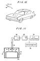
- Figure 10 shows that when external waves W such as radio or other waves passes through the vehicle body B of an electrically conductive metal, surface currents I depending on the intensity of the external waves are induced on the vehicle body at various different locations.
- the present antenna system is intended to receive only external radio or other waves belonging to relatively high frequency bands equal to or more than 50 MHz.
- the present invention can make use of a measurement of the distribution of surface currents induced on the vehicle body by such external waves to determine a location on the vehicle body at which the density of the surface currents is high with less noise, that is, a position in which the pick-up is desirably located in accordance with the principle of the present invention.
- the distribution of surface currents may be determined by a simulation by a computer and actual measurements of current intensity at various different locations on the vehicle body.
- a probe constructed and functioning in accordance with the same principle as that of the high-frequency pick-up of the present antenna system is used such that it is moved over the entire surface of the vehicle body while being angularly rotated at various different locations on the vehicle body.
- FIG 11 shows such a probe P which comprises a casing 10 of an electrically conductive material and a loop coil 12 contained within the casing 10 and shielded by the casting 10.
- the casing 10 is provided with an opening 10a through which a portion of the loop antenna 12 is externally exposed.
- the exposed portion of the loop antenna 12 is positioned in close proximity to the surface of the vehicle body to detect a magnetic flux formed by surface currents on the vehicle body.
- the loop coil 12 is electrically connected with the casing 10 through a short-circuiting line 14.
- the output terminal 16 of the loop antenna 12 is electrically connected with a core conductor 20 in a coaxial cable 18.
- the loop antenna 12 includes a capacitor 22 connected in series therewith and which functions to cause the frequency of the loop antenna 12 to resonate which a desired frequency to be measured so that the efficiency of the pick-up can be increased.
- the distribution and orientation of surface currents on the vehicle body can accurately be determined.
- the output of the probe P is amplified by a high-frequency voltage amplifier 24 the output of which in turn is measured by a high-frequency measuring device 26 and also recorded by an X-Y recorder 28 as a value of the surface currents on the vehicle body at each of various different locations.
- the X-Y recorder 28 receives from a potentiometer 30 a signal indicative of each of the locations on the vehicle body. In such a manner, one can accurately know values of surface currents corresponding to the respective locations on the vehicle body.
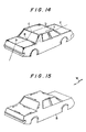
- a high-frequency pick-up is desirably located on one of the marginal edges of the trunk lid along its length to detect surface currents flowing concentratedly on the marginal edge of the trunk lid.
- Figure 17 shows the distribution of surface currents induced on the roof of the vehicle body while Figure 18 shows the distribution of surface currents induced on the engine hood of the vehicle body.
- a high-frequency pick-up is located on one of the marginal edges of the roof and engine hood, the maximum currents can similarly be detected by the high-frequency pick-up. It is thus understood that radio or other waves can more sensitively be received by the pick-up at the marginal edge of each of various different vehicle portions. If is of course appreciated that the high-frequency pick-up may similarly be mounted on a pillar or fender of the vehicle body.
- the high-frequency pick-up is located in close proximity to the marginal edge of a vehicle portion on the vehicle body with its longitudinal portion extending parallel to that marginal edge. To obtain very excellent sensitivity, the high-frequency pick-up is desirably spaced from the marginal edge of the vehicle portion inwardly within a certain range depending on the carrier frequency of radio or other waves to be received.
- Figures 16 to 18 illustrates the distribution of surface currents induced on the vehicle body by FM radio waves having a frequency equal to 80 MHz. Considering the decrease of surface currents from maximum up to 6 dB in connection with the spacing between the marginal edges of the vehicle portion and the high-frequency pick-up, it has been found that when the high-frequency pick-up is spaced from the marginal edge of the vehicle portion within a distance of 4.5 cm, the antenna system may provide excellent sensitivity.
- This practicable spacing between the high-frequency pick-up and the marginal edge of the vehicle portion depends on the level of the carrier frequency of radio or other waves to be received. As the level of the carrier frequency increases, the spacing decreases.
- the practicable spacing between the high-frequency pick-up and the marginal edge of the vehicle portion is inversely proportional to the carrier frequency of radio or other waves to be received. Therefore, the high-frequency pick-up should be spaced inwardly from the marginal edge of one of the vehicle portions within a range determined by the following formula: where c is the velocity of light and f is the carrier frequency.
- c is the velocity of light
- f is the carrier frequency.
- the high-frequency pick-up can efficiently receive radio or other waves when it is located on the vehicle body in close proximity to the marginal edge of one of the vehicle portions, but spaced from that marginal edge within said range.
- the high-frequency pick-up may be spaced from the marginal edge of the vehicle portion within a distance of 3.6 cm. As the carrier frequency f increases, the high-frequency pick-up will be located on the vehicle body nearer the marginal edge of the vehicle portion.
- a high-frequency pick-up 38 comprising an antenna casing 32 in which a loop antenna 42 is housed for detecting surface high-frequency currents on the vehicle body.
- the high-frequency pick-up 38 also comprises a circuit casing 34 which contains a circuitry 58 for matching and amplifying signals, the circuitry being electrically connected with the loop antenna 32.
- the high-frequency pick-up 38 is of an electromagnetic coupling type which is disposed in close proximity to the marginal edge of one of the vehicle portions.
- Signals processed by the circuitry 58 are fed out through a coaxial cable 60 and then further processed by a circuit similar to that used in determining the distribution of surface currents.
- the circuitry 58 is supplied with power and control signals through a cable 62.
- the loop antenna 42 is in the form of a single- winding coil which is covered with a suitable insulating material such that the coil can be electrically insulated from and disposed in close proximity to the marginal edge of the vehicle portion. Accordingly, a magnetic flux formed by the surface currents on the vehicle body can more effetively intersect the loop antenna 42.
- the antenna casing 32 is made of any suitable synthetic resin and then protects the loop antenna 42 from any external impact or force.
- the circuit casing 34 is made of a metal plate and rigidly connected with the antenna casing 32.
- the synthetic resin casing 32 makes it possible that a magnetic flux formed on the marginal edge of the vehicle portion can be detected through an increased range.
- the metal casing 34 is electrically connected with the shield layer of the coaxial cable 60 to provide a wall structure for shielding any static electricity.
- the circuitry 58 can be protected by the metal casing 34 from influence of noise.
- the portion of the antenna casing 32 to be opposed to the marginal edge of a vehicle portion on which the antenna system is to be mounted is provided with an opening 36 extending along the longitudinal portion of the loop antenna 42 which is housed within this antenna casing 32.
- the opening 36 is in the form of a slit and serves as means for guiding and positioning the high-frequency pick-up 38 relative to the marginal edge of the vehicle portion.
- the inner portion of the opening 36 locates in position one longer side of the loop antenna 42.
- the antenna casing 32 includes a forward thick-walled end portion to be opposed to the marginal edge of a vehicle portion on which the antenna system is to be mounted.
- This forward thick-walled end portion of the casing 32 is formed with a first opening 36a which is of a rectangular shape extending parallel to the longer side of the loop antenna 42 in the casing 32.
- the slit opening 36 takes the form of the first opening 36a which provides its outer portion and a second opening 36b which provides its inner portion and through which the longer side of the loop antenna 42 is exposed externally, that is, into the first opening 36a.
- These communicating first and second openings 36a an 36b form the slit opening 36 and serve as means for mutually locating the loop antenna 42 and the marginal edge of the vehicle portion, respectively.
- the detecting side of the loop antenna 42 is inserted into and positioned in the second opening 36b of the casing 32.
- the second opening 36b of the casing 32 has a width substantially equal to the diameter of the loop antenna 42. Therefore, the detecting side of the loop antenna 42 can firmly be held, i.e. located, in the second opening 36b. As a result, any undesirable vibration can effectively be avoided at the loop antenna 42 even when the vehicle runs.
- the high-frequency pick-up 38 is mounted on the vehicle body such that the opening 36a of the casing 32 communicating with the second opening 36b thereof receives the marginal edge of an inner panel member 44 of the vehicle body.
- the loop antenna 42 can be located in a predetermined position relative to the marginal edge of the inner panel 44 of the vehicle body.
- the high-frequency pick-up 38 thus positioned can then be connected rigidly with the vehicle body by adjustable mounting bracket means (not shown).
- the high-frequency pick-up 38 can properly be positioned on the vehicle body by the use of the opening 36 in the casing 32 such that the loop antenna 42 therein will be disposed in close proximity to the inner panel member of the vehicle body, the high-frequency pick-up 38 can readily be mounted on the vehicle body. Furthermore, surface high-frequency currents induced on the vehicle body by radio or other waves can efficiently be detected by the high-frequency pick-up 38 since the loop antenna can be disposed as near the marginal edge of the vehicle portion as possible.
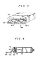
- FIG. 3 and 4 there is shown another embodiment of a high-frequency pick-up used in an antenna system according to the present invention in which parts similar to those of the previously described embodiment are denoted by similar reference numerals increased by one hundred.
- the embodiment shown in Figures 3 and 4 can accommodate to various vehicle members different from each other in thickness.
- a casing 132 has a first opening 136a of rectangular cross-section which is formed in the forward end of the casing 132.
- the first opening 136a has upper and lower walls on each of which a plurality of guide elements 46-1, 46-2 and 46-3 are removably mounted and spaced from one another along the length of the upper or lower wall.
- the guide elements 46 on the upper wall of the opening 136a are positioned respectively relative to those on the lower wall of the same to define guide groove means 48 for properly positioning the marginal edge of the inner panel member 144 relative to a loop antenna 142 housed within the casing 132.
- the guide elements 46 in the opening 136a may readily be replaced by other guide elements each having a different size to define guide groove means for receiving the marginal edge of another inner panel member 144 having a different thickness.
- the guide elements 46 may be made of the same material as in the casing 132 to reduce the entire weight of the casing 132.
- Figures 5 and 6 show still another embodiments of a high-frequency pick-up used in an antenna system according to the present invention.
- parts similar to those of the first invention shown in Figures 1 and 2 are designated by similar reference numerals increased by two hundred.
- parts similar to those of the first embodiment are denoted by similar reference numerals increased by three hundred.
- a casing includes an opening having guiding and positioning elements of a cushion material mounted on the upper and lower walls of the opening to prevent the inner panel member from vibrating in the opening.
- a casing 323 shown in Figure 5 includes a first opening 236a which includes cushioning members 50 mounted on the upper and lower walls of the opening 236a. These cushioning members 50 resiliently support the marginal edge of an inner panel member 244.
- a casing 332 shown in Figure 6 comprises a first opening which includes similar guide elements 346 defining guide groove means 348.
- the guide groove means 348 includes cushioning members 52 mounted on the upper and lower walls thereof for resiliently supporting the marginal edge of an inner panel member 344.
- the cushioning members 50 and 52 may be formed of any suitable resilient material such as rubber plate or the like.
- each of the loop antennas 242 or 342 can properly and positively be held against the marginal edge of each of the inner panel members 244 or 344 to provide antenna outputs steadily.
- cushioning members 50 or 52 are made of ferrite rubber containing magnetic particles, a magnetic flux formed by the surface currents on the vehicle body can more efficiently intersect the loop antenna to increase the output of the pick-up.
- FIG. 7 shows a preferred form of a loop antenna used in the present invention.
- the loop antenna 42 is formed by a length of copper wire 70 having a round or square cross-section.
- the opposite ends of the copper wire 70 are soldered on a through hole print circuit board 45 definining a matching and amplifying circuit as shown at 72.
- the portion of the copper wire 70 other than the soldered ends 72 is covered with an insulation 74 which is made of any suitable dielectric material such as enamel, polyvinyl chloride, the material sold under the Trade Mark Teflon, polyethylene, polyester or the like.
- the dielectric material can insulate the loop antenna 42 from the marginal edge of the vehicle body so that the output fed from the loop antenna 42 can be prevented from being reduced.
- the loop antenna 42 is preferably formed of a good conductor having a reduced internal resistance, such as steel wire, copper wire, aluminium wire or the like.
- the loop antenna 42 is formed by a length of aluminium wire, it may be treated by heat to form alumina (A1 2 0 3 ) as an insulation on the surface of the wire.
- the insulation 74 may also include a body of epoxy resin impregnated and cured with a high dielectric material such as ferrite particles and particularly Mn-Zn ferrite particles. Such an insulation 74 electrically separates the loop antenna 42 from the marginal edge of the vehicle body while causing the loop antenna 42 to efficiently detect the surface currents flowing on the marginal edge of the vehicle body. Consequently, the sensitivity of the pick-up 38 can be increased.
- FIGS 8 and 9 illustrate the aforementioned high-frequency pick-up 38 mounted on the vehicle body near the marginal edge of the rearward roof portion 80 thereof.
- the uncovered roof panel portion 80 of a metallic material which includes a rear window frame 82 located at the marginal edge portion thereof and mounting a rear window glass 84.
- the high-frequency pick-up 38 is spaced from the marginal edge of the rear window frame 82 within a range of 4.5 cm.
- the rear window frame 82 is provided with an opening 82a in which the high-frequency pick-up 38 comprising the two casings 32 and 34 is located such that the loop antenna 42 therein can be positioned relative to the marginal edge of the rear window frame 82.
- the exposed side of the loop antenna 42 positioned within the opening of the casing 32 is spaced from the marginal edge of the rear window frame 82 within a distance of 4.5 cm.
- the loop antenna 42 can positively receive FM radio waves having a frequency equal to 80 MHzfrom the surface currents flowing on the marginal edge of the rear window frame 82. Since the surface currents flow on the marginal edge of the rear window frame 82 in the direction parallel thereto as seen from Figure 15, the longer side of the loop antenna 42 is disposed parallel to the marginal edge of the rear window frame 82.
- the loop antenna Since the loop antenna is coated with the dielectric insulation 74, the loop antenna 42 can electrically be separated from the marginal edge of the vehicle body. Therefore, the sensitivity of the pick-up 38 will not be reduced.
- the insulation 74 is made of epoxy resin impregnated with magnetic particles such as ferrite particles, the sensitivity of the pick-up 38 can further be improved while maintaining the insulation between the loop antenna 42 and the marginal edge of the vehicle body.
Landscapes
- Engineering & Computer Science (AREA)
- Remote Sensing (AREA)
- Details Of Aerials (AREA)
Priority Applications (1)
| Application Number | Priority Date | Filing Date | Title |
|---|---|---|---|
| AT85308294T ATE60466T1 (de) | 1984-11-15 | 1985-11-14 | Kraftfahrzeugantennensystem. |
Applications Claiming Priority (4)
| Application Number | Priority Date | Filing Date | Title |
|---|---|---|---|
| JP24209884A JPS61120504A (ja) | 1984-11-15 | 1984-11-15 | 自動車用アンテナのピツクアツプ |
| JP242098/84 | 1984-11-15 | ||
| JP258949/84 | 1984-12-07 | ||
| JP25894984A JPH0612848B2 (ja) | 1984-12-07 | 1984-12-07 | 自動車用アンテナ装置 |
Publications (2)
| Publication Number | Publication Date |
|---|---|
| EP0181782A1 EP0181782A1 (en) | 1986-05-21 |
| EP0181782B1 true EP0181782B1 (en) | 1991-01-23 |
Family
ID=26535608
Family Applications (1)
| Application Number | Title | Priority Date | Filing Date |
|---|---|---|---|
| EP85308294A Expired EP0181782B1 (en) | 1984-11-15 | 1985-11-14 | Automobile antenna system |
Country Status (5)
| Country | Link |
|---|---|
| US (1) | US4717921A (da) |
| EP (1) | EP0181782B1 (da) |
| CA (1) | CA1252881A (da) |
| DE (1) | DE3581495D1 (da) |
| DK (1) | DK525485A (da) |
Families Citing this family (12)
| Publication number | Priority date | Publication date | Assignee | Title |
|---|---|---|---|---|
| CA1254654A (en) * | 1984-11-15 | 1989-05-23 | Junzo Ohe | Automobile antenna system |
| CA1245352A (en) * | 1984-11-26 | 1988-11-22 | Junzo Ohe | Automobile antenna system |
| JPH0642605B2 (ja) * | 1985-08-09 | 1994-06-01 | トヨタ自動車株式会社 | 自動車用アンテナ装置 |
| US5248989A (en) * | 1988-02-04 | 1993-09-28 | Unisan Ltd. | Magnetic field concentrator |
| GB2250637A (en) * | 1990-12-05 | 1992-06-10 | Leslie James Wallen | Isolated antenna bases |
| JPH1188034A (ja) * | 1997-09-04 | 1999-03-30 | Harada Ind Co Ltd | Gps波用アンテナ装置 |
| JP4037703B2 (ja) * | 2002-06-28 | 2008-01-23 | 日本電気株式会社 | 内蔵アンテナ及び無線機 |
| US6842140B2 (en) * | 2002-12-03 | 2005-01-11 | Harris Corporation | High efficiency slot fed microstrip patch antenna |
| US7193582B2 (en) * | 2005-06-13 | 2007-03-20 | Trans Electric Co., Ltd. | Digital receiving antenna device for a digital television |
| CN102956952B (zh) * | 2012-10-25 | 2018-02-13 | 西安开容电子技术有限责任公司 | 一种小型化便携式近场测试天线的设计方法 |
| US8903020B2 (en) * | 2012-11-19 | 2014-12-02 | Yi Chang Hsiang Industrial, Co., Ltd. | Radio signal receiving system |
| CN112105147B (zh) * | 2020-09-24 | 2021-11-16 | 湖北亿咖通科技有限公司 | 一种车载娱乐系统主机 |
Family Cites Families (60)
| Publication number | Priority date | Publication date | Assignee | Title |
|---|---|---|---|---|
| FR824159A (fr) * | 1936-07-11 | 1938-02-02 | Opel Adam Ag | Antenne pour la réception d'émissions de t. s. f. dans les voitures automobiles |
| US2200574A (en) * | 1939-10-14 | 1940-05-14 | Harold G Davis | Reversible power transmission mechanism |
| US2404093A (en) * | 1941-06-28 | 1946-07-16 | Rca Corp | Antenna |
| US2474794A (en) * | 1944-01-17 | 1949-06-28 | Measurements Corp | Attenuator |
| US2481978A (en) * | 1947-01-22 | 1949-09-13 | Joseph B Clough | Automobile radio coupler and method of communication |
| US2520984A (en) * | 1947-01-25 | 1950-09-05 | Motorola Inc | Antenna system |
| US2520986A (en) * | 1947-10-22 | 1950-09-05 | Motorola Inc | Vehicular antenna system |
| US2520985A (en) * | 1947-10-22 | 1950-09-05 | Motorola Inc | Antenna coupling circuit |
| US2575471A (en) * | 1950-04-13 | 1951-11-20 | Philco Corp | Vehicular antenna system |
| DE889618C (de) * | 1951-09-27 | 1953-09-10 | Lorenz C Ag | Kraftwagenantennenanlage |
| US2740113A (en) * | 1952-01-03 | 1956-03-27 | Bendix Aviat Corp | Magnetic antenna systems |
| US2774811A (en) * | 1954-03-02 | 1956-12-18 | Shanok Abraham | Antenna and trim |
| US3007164A (en) * | 1955-04-22 | 1961-10-31 | Ross A Davis | Slot antenna which is fed at two points |
| US2971191A (en) * | 1955-07-18 | 1961-02-07 | Ross A Davis | Slot type antenna having an autotransformer coupling circuit |
| US2950479A (en) * | 1955-12-05 | 1960-08-23 | Gen Electric | Loop antenna utilizing conductive cabinet |
| US3066293A (en) * | 1956-03-16 | 1962-11-27 | Ross A Davis | Antenna system with output means in parallel with resonating means |
| US2859441A (en) * | 1957-06-21 | 1958-11-04 | Rosenbaum Jacob | Automobile radio antenna |
| DE1131762B (de) * | 1957-10-15 | 1962-06-20 | Arnaldo Piccinini | Rundfunkempfaenger mit in Rahmenbauart ausgebildeter und einen Ferritkern aufweisender Gehaeuseantenne fuer Kraftfahzeuge |
| US3210766A (en) * | 1962-02-15 | 1965-10-05 | Ralph O Parker | Slot type antenna with tuning circuit |
| US3364487A (en) * | 1964-12-01 | 1968-01-16 | Rosario J. Maheux | Portable radio receiver antenna coupler set |
| DE1949828A1 (de) * | 1968-10-04 | 1970-04-30 | Portenseigne Ets Marcel | Verfahren und Vorrichtung zum Empfangen radiofrequenter Signale |
| JPS4836583B1 (da) * | 1969-06-13 | 1973-11-06 | ||
| JPS5033076Y1 (da) * | 1969-12-09 | 1975-09-26 | ||
| DE7015306U (de) * | 1970-04-24 | 1970-09-24 | Kolbe & Co Hans | Kraftfahrzeugantenne. |
| US3717876A (en) * | 1971-04-23 | 1973-02-20 | Volkers Res Corp | Ferrite antenna coupled to radio frequency currents in vehicle body |
| US3742508A (en) * | 1971-06-01 | 1973-06-26 | Gen Motors Corp | Inconspicuous vehicle mounted radio antenna |
| US3823403A (en) * | 1971-06-09 | 1974-07-09 | Univ Ohio State Res Found | Multiturn loop antenna |
| US3794997A (en) * | 1971-09-30 | 1974-02-26 | Toyota Motor Co Ltd | Vehicle with apparatus for detecting potential collisions |
| HU170360B (da) * | 1973-05-23 | 1977-05-28 | ||
| US3916413A (en) * | 1973-12-21 | 1975-10-28 | Ross Alan Davis | Remotely tuned conductive-body antenna system |
| US3961330A (en) * | 1973-12-21 | 1976-06-01 | Ross Alan Davis | Antenna system utilizing currents in conductive body |
| US3961292A (en) * | 1974-01-02 | 1976-06-01 | Ross Alan Davis | Radio frequency transformer |
| US3972048A (en) * | 1974-11-29 | 1976-07-27 | Ross Alan Davis | FM-AM windshield antenna |
| US4003056A (en) * | 1975-05-20 | 1977-01-11 | Ross Alan Davis | Windshield antenna system with resonant element and cooperating resonant conductive edge |
| US4080603A (en) * | 1976-07-12 | 1978-03-21 | Howard Belmont Moody | Transmitting and receiving loop antenna with reactive loading |
| DE2701921A1 (de) * | 1977-01-19 | 1978-07-20 | Angel Dr Ing Jotzoff | Dem wagen integriertes antennengebilde insbesondere fuer autoradios |
| DE2733478B2 (de) * | 1977-07-25 | 1980-04-17 | Hans Heinrich Prof. Dr. Dr.-Ing.E.H. 8035 Gauting Meinke | Antenne in Form eines Kraftfahrzeuges |
| DE2745475A1 (de) * | 1977-10-08 | 1979-04-12 | Juergen Fischer | Antenne fuer kraftfahrzeuge |
| JPS54128653A (en) * | 1978-03-30 | 1979-10-05 | Nippon Gakki Seizo Kk | Antenna unit for receiver |
| JPS5947882B2 (ja) * | 1978-04-11 | 1984-11-22 | 旭硝子株式会社 | 自動車のアンテナガラス |
| DE2821202A1 (de) * | 1978-05-13 | 1979-11-22 | Juergen Keck | Durch eine kapazitaetsdiode abgestimmte elektronische autoantenne |
| US4217591A (en) * | 1978-09-20 | 1980-08-12 | The United States Of America As Represented By The Secretary Of The Army | High frequency roll-bar loop antenna |
| JPS5827681B2 (ja) * | 1978-09-29 | 1983-06-10 | 日本国有鉄道 | 車両用誘導無線ル−プアンテナの取付構造 |
| US4317121A (en) * | 1980-02-15 | 1982-02-23 | Lockheed Corporation | Conformal HF loop antenna |
| JPS56156031A (en) * | 1980-05-07 | 1981-12-02 | Nissan Motor Co Ltd | Diversity receiver for vehicle |
| JPS56168441A (en) * | 1980-05-30 | 1981-12-24 | Nissan Motor Co Ltd | Diversity receiver for car |
| US4339827A (en) * | 1980-11-25 | 1982-07-13 | Rca Corporation | Automatic tuning circuit arrangement with switched impedances |
| JPS5870642A (ja) * | 1981-10-22 | 1983-04-27 | Toyota Motor Corp | 自動車用受信装置 |
| JPS5870640A (ja) * | 1981-10-22 | 1983-04-27 | Toyota Motor Corp | ダイバ−シテイ受信システム |
| JPS5944861A (ja) * | 1982-09-07 | 1984-03-13 | Fujitsu Ltd | 半導体装置およびその製造方法 |
| US4566133A (en) * | 1982-12-27 | 1986-01-21 | Commtech International | Switched diversity method and apparatus for FM receivers |
| US4499606A (en) * | 1982-12-27 | 1985-02-12 | Sri International | Reception enhancement in mobile FM broadcast receivers and the like |
| US4506267A (en) * | 1983-01-26 | 1985-03-19 | Geophysical Survey Systems, Inc. | Frequency independent shielded loop antenna |
| JPS59181732A (ja) * | 1983-03-31 | 1984-10-16 | Toshiba Corp | 携帯用無線機におけるダイバ−シチ−受信方式 |
| JPS60129464A (ja) * | 1983-12-17 | 1985-07-10 | Riken Corp | カム駒及びその製造方法 |
| JPS60172804A (ja) * | 1984-10-09 | 1985-09-06 | Toyota Motor Corp | 車両用アンテナ装置 |
| JPH0622283B2 (ja) * | 1984-10-26 | 1994-03-23 | トヨタ自動車株式会社 | 自動車用アンテナ装置 |
| US4717922A (en) * | 1984-11-06 | 1988-01-05 | Toyota Jidosha Kabushiki Kaisha | Automobile antenna system |
| CA1249052A (en) * | 1984-11-08 | 1989-01-17 | Junzo Ohe | Automobile antenna system |
| CA1245352A (en) * | 1984-11-26 | 1988-11-22 | Junzo Ohe | Automobile antenna system |
-
1985
- 1985-11-14 DK DK525485A patent/DK525485A/da not_active Application Discontinuation
- 1985-11-14 EP EP85308294A patent/EP0181782B1/en not_active Expired
- 1985-11-14 DE DE8585308294T patent/DE3581495D1/de not_active Expired - Lifetime
- 1985-11-14 CA CA000495290A patent/CA1252881A/en not_active Expired
- 1985-11-14 US US06/798,022 patent/US4717921A/en not_active Expired - Lifetime
Also Published As
| Publication number | Publication date |
|---|---|
| US4717921A (en) | 1988-01-05 |
| DK525485A (da) | 1986-05-16 |
| DE3581495D1 (de) | 1991-02-28 |
| CA1252881A (en) | 1989-04-18 |
| DK525485D0 (da) | 1985-11-14 |
| EP0181782A1 (en) | 1986-05-21 |
Similar Documents
| Publication | Publication Date | Title |
|---|---|---|
| EP0183523B1 (en) | Automobile antenna system | |
| CA1256988A (en) | Automobile antenna | |
| EP0182497B1 (en) | Automobile antenna | |
| EP0181782B1 (en) | Automobile antenna system | |
| EP0181120B1 (en) | Automobile antenna system | |
| EP0183521B1 (en) | Automobile antenna system | |
| EP0221694A2 (en) | Vehicle antenna system | |
| EP0211637B1 (en) | Vehicle antenna system | |
| EP0223398B1 (en) | Vehicle antenna system | |
| EP0180462B1 (en) | Automobile antenna system | |
| EP0182614B1 (en) | Automobile antenna system | |
| US4792807A (en) | Automobile antenna system | |
| EP0183522B1 (en) | Automobile antenna device | |
| EP0213743B1 (en) | Automobile antenna system | |
| JPS61120504A (ja) | 自動車用アンテナのピツクアツプ | |
| JPS61129907A (ja) | 自動車用アンテナ装置 | |
| JPS61127206A (ja) | 自動車用アンテナ装置 | |
| JPS61129906A (ja) | 車両用アンテナ装置 | |
| JPH0652849B2 (ja) | 自動車用アンテナのピツクアツプ | |
| JPS61136303A (ja) | 自動車用アンテナ装置 | |
| JPS61105907A (ja) | 自動車用アンテナ装置 | |
| JPS61137402A (ja) | 自動車用アンテナ装置 |
Legal Events
| Date | Code | Title | Description |
|---|---|---|---|
| PUAI | Public reference made under article 153(3) epc to a published international application that has entered the european phase |
Free format text: ORIGINAL CODE: 0009012 |
|
| AK | Designated contracting states |
Kind code of ref document: A1 Designated state(s): AT CH DE FR GB LI SE |
|
| 17P | Request for examination filed |
Effective date: 19860731 |
|
| 17Q | First examination report despatched |
Effective date: 19880506 |
|
| GRAA | (expected) grant |
Free format text: ORIGINAL CODE: 0009210 |
|
| AK | Designated contracting states |
Kind code of ref document: B1 Designated state(s): AT CH DE FR GB LI SE |
|
| REF | Corresponds to: |
Ref document number: 60466 Country of ref document: AT Date of ref document: 19910215 Kind code of ref document: T |
|
| ET | Fr: translation filed | ||
| REF | Corresponds to: |
Ref document number: 3581495 Country of ref document: DE Date of ref document: 19910228 |
|
| PLBE | No opposition filed within time limit |
Free format text: ORIGINAL CODE: 0009261 |
|
| STAA | Information on the status of an ep patent application or granted ep patent |
Free format text: STATUS: NO OPPOSITION FILED WITHIN TIME LIMIT |
|
| 26N | No opposition filed | ||
| EAL | Se: european patent in force in sweden |
Ref document number: 85308294.9 |
|
| REG | Reference to a national code |
Ref country code: GB Ref legal event code: 746 Effective date: 19950807 |
|
| REG | Reference to a national code |
Ref country code: FR Ref legal event code: D6 |
|
| PGFP | Annual fee paid to national office [announced via postgrant information from national office to epo] |
Ref country code: SE Payment date: 19981105 Year of fee payment: 14 |
|
| PGFP | Annual fee paid to national office [announced via postgrant information from national office to epo] |
Ref country code: FR Payment date: 19981110 Year of fee payment: 14 |
|
| PGFP | Annual fee paid to national office [announced via postgrant information from national office to epo] |
Ref country code: AT Payment date: 19981112 Year of fee payment: 14 |
|
| PGFP | Annual fee paid to national office [announced via postgrant information from national office to epo] |
Ref country code: GB Payment date: 19981120 Year of fee payment: 14 Ref country code: DE Payment date: 19981120 Year of fee payment: 14 Ref country code: CH Payment date: 19981120 Year of fee payment: 14 |
|
| PG25 | Lapsed in a contracting state [announced via postgrant information from national office to epo] |
Ref country code: GB Free format text: LAPSE BECAUSE OF NON-PAYMENT OF DUE FEES Effective date: 19991114 Ref country code: AT Free format text: LAPSE BECAUSE OF NON-PAYMENT OF DUE FEES Effective date: 19991114 |
|
| PG25 | Lapsed in a contracting state [announced via postgrant information from national office to epo] |
Ref country code: SE Free format text: LAPSE BECAUSE OF NON-PAYMENT OF DUE FEES Effective date: 19991115 |
|
| PG25 | Lapsed in a contracting state [announced via postgrant information from national office to epo] |
Ref country code: LI Free format text: LAPSE BECAUSE OF NON-PAYMENT OF DUE FEES Effective date: 19991130 Ref country code: CH Free format text: LAPSE BECAUSE OF NON-PAYMENT OF DUE FEES Effective date: 19991130 |
|
| GBPC | Gb: european patent ceased through non-payment of renewal fee |
Effective date: 19991114 |
|
| REG | Reference to a national code |
Ref country code: CH Ref legal event code: PL |
|
| EUG | Se: european patent has lapsed |
Ref document number: 85308294.9 |
|
| PG25 | Lapsed in a contracting state [announced via postgrant information from national office to epo] |
Ref country code: FR Free format text: LAPSE BECAUSE OF NON-PAYMENT OF DUE FEES Effective date: 20000731 |
|
| PG25 | Lapsed in a contracting state [announced via postgrant information from national office to epo] |
Ref country code: DE Free format text: LAPSE BECAUSE OF NON-PAYMENT OF DUE FEES Effective date: 20000901 |
|
| REG | Reference to a national code |
Ref country code: FR Ref legal event code: ST |