EP0182019B1 - Bande protectrice contre les accidents - Google Patents
Bande protectrice contre les accidents Download PDFInfo
- Publication number
- EP0182019B1 EP0182019B1 EP85110991A EP85110991A EP0182019B1 EP 0182019 B1 EP0182019 B1 EP 0182019B1 EP 85110991 A EP85110991 A EP 85110991A EP 85110991 A EP85110991 A EP 85110991A EP 0182019 B1 EP0182019 B1 EP 0182019B1
- Authority
- EP
- European Patent Office
- Prior art keywords
- door
- accident prevention
- pressure
- door leaf
- signal
- Prior art date
- Legal status (The legal status is an assumption and is not a legal conclusion. Google has not performed a legal analysis and makes no representation as to the accuracy of the status listed.)
- Expired
Links
Images

Classifications
-
- E—FIXED CONSTRUCTIONS
- E06—DOORS, WINDOWS, SHUTTERS, OR ROLLER BLINDS IN GENERAL; LADDERS
- E06B—FIXED OR MOVABLE CLOSURES FOR OPENINGS IN BUILDINGS, VEHICLES, FENCES OR LIKE ENCLOSURES IN GENERAL, e.g. DOORS, WINDOWS, BLINDS, GATES
- E06B9/00—Screening or protective devices for wall or similar openings, with or without operating or securing mechanisms; Closures of similar construction
- E06B9/56—Operating, guiding or securing devices or arrangements for roll-type closures; Spring drums; Tape drums; Counterweighting arrangements therefor
- E06B9/80—Safety measures against dropping or unauthorised opening; Braking or immobilising devices; Devices for limiting unrolling
- E06B9/82—Safety measures against dropping or unauthorised opening; Braking or immobilising devices; Devices for limiting unrolling automatic
- E06B9/88—Safety measures against dropping or unauthorised opening; Braking or immobilising devices; Devices for limiting unrolling automatic for limiting unrolling
-
- E—FIXED CONSTRUCTIONS
- E05—LOCKS; KEYS; WINDOW OR DOOR FITTINGS; SAFES
- E05F—DEVICES FOR MOVING WINGS INTO OPEN OR CLOSED POSITION; CHECKS FOR WINGS; WING FITTINGS NOT OTHERWISE PROVIDED FOR, CONCERNED WITH THE FUNCTIONING OF THE WING
- E05F15/00—Power-operated mechanisms for wings
- E05F15/40—Safety devices, e.g. detection of obstructions or end positions
- E05F15/42—Detection using safety edges
-
- E—FIXED CONSTRUCTIONS
- E06—DOORS, WINDOWS, SHUTTERS, OR ROLLER BLINDS IN GENERAL; LADDERS
- E06B—FIXED OR MOVABLE CLOSURES FOR OPENINGS IN BUILDINGS, VEHICLES, FENCES OR LIKE ENCLOSURES IN GENERAL, e.g. DOORS, WINDOWS, BLINDS, GATES
- E06B9/00—Screening or protective devices for wall or similar openings, with or without operating or securing mechanisms; Closures of similar construction
- E06B9/02—Shutters, movable grilles, or other safety closing devices, e.g. against burglary
- E06B9/08—Roll-type closures
- E06B9/11—Roller shutters
- E06B9/17—Parts or details of roller shutters, e.g. suspension devices, shutter boxes, wicket doors, ventilation openings
- E06B9/17046—Bottom bars
-
- E—FIXED CONSTRUCTIONS
- E05—LOCKS; KEYS; WINDOW OR DOOR FITTINGS; SAFES
- E05F—DEVICES FOR MOVING WINGS INTO OPEN OR CLOSED POSITION; CHECKS FOR WINGS; WING FITTINGS NOT OTHERWISE PROVIDED FOR, CONCERNED WITH THE FUNCTIONING OF THE WING
- E05F15/00—Power-operated mechanisms for wings
- E05F15/40—Safety devices, e.g. detection of obstructions or end positions
- E05F15/42—Detection using safety edges
- E05F2015/487—Fault detection of safety edges
-
- E—FIXED CONSTRUCTIONS
- E05—LOCKS; KEYS; WINDOW OR DOOR FITTINGS; SAFES
- E05Y—INDEXING SCHEME ASSOCIATED WITH SUBCLASSES E05D AND E05F, RELATING TO CONSTRUCTION ELEMENTS, ELECTRIC CONTROL, POWER SUPPLY, POWER SIGNAL OR TRANSMISSION, USER INTERFACES, MOUNTING OR COUPLING, DETAILS, ACCESSORIES, AUXILIARY OPERATIONS NOT OTHERWISE PROVIDED FOR, APPLICATION THEREOF
- E05Y2400/00—Electronic control; Electrical power; Power supply; Power or signal transmission; User interfaces
- E05Y2400/65—Power or signal transmission
- E05Y2400/66—Wireless transmission
- E05Y2400/664—Wireless transmission by radio waves
-
- E—FIXED CONSTRUCTIONS
- E05—LOCKS; KEYS; WINDOW OR DOOR FITTINGS; SAFES
- E05Y—INDEXING SCHEME ASSOCIATED WITH SUBCLASSES E05D AND E05F, RELATING TO CONSTRUCTION ELEMENTS, ELECTRIC CONTROL, POWER SUPPLY, POWER SIGNAL OR TRANSMISSION, USER INTERFACES, MOUNTING OR COUPLING, DETAILS, ACCESSORIES, AUXILIARY OPERATIONS NOT OTHERWISE PROVIDED FOR, APPLICATION THEREOF
- E05Y2900/00—Application of doors, windows, wings or fittings thereof
- E05Y2900/10—Application of doors, windows, wings or fittings thereof for buildings or parts thereof
- E05Y2900/106—Application of doors, windows, wings or fittings thereof for buildings or parts thereof for garages
-
- E—FIXED CONSTRUCTIONS
- E06—DOORS, WINDOWS, SHUTTERS, OR ROLLER BLINDS IN GENERAL; LADDERS
- E06B—FIXED OR MOVABLE CLOSURES FOR OPENINGS IN BUILDINGS, VEHICLES, FENCES OR LIKE ENCLOSURES IN GENERAL, e.g. DOORS, WINDOWS, BLINDS, GATES
- E06B9/00—Screening or protective devices for wall or similar openings, with or without operating or securing mechanisms; Closures of similar construction
- E06B9/02—Shutters, movable grilles, or other safety closing devices, e.g. against burglary
- E06B9/08—Roll-type closures
- E06B9/11—Roller shutters
- E06B9/17—Parts or details of roller shutters, e.g. suspension devices, shutter boxes, wicket doors, ventilation openings
- E06B9/17076—Sealing or antirattling arrangements
- E06B2009/17084—Sealing or antirattling arrangements closing outlet slot of shutter box
-
- E—FIXED CONSTRUCTIONS
- E06—DOORS, WINDOWS, SHUTTERS, OR ROLLER BLINDS IN GENERAL; LADDERS
- E06B—FIXED OR MOVABLE CLOSURES FOR OPENINGS IN BUILDINGS, VEHICLES, FENCES OR LIKE ENCLOSURES IN GENERAL, e.g. DOORS, WINDOWS, BLINDS, GATES
- E06B9/00—Screening or protective devices for wall or similar openings, with or without operating or securing mechanisms; Closures of similar construction
- E06B9/56—Operating, guiding or securing devices or arrangements for roll-type closures; Spring drums; Tape drums; Counterweighting arrangements therefor
- E06B9/80—Safety measures against dropping or unauthorised opening; Braking or immobilising devices; Devices for limiting unrolling
- E06B9/82—Safety measures against dropping or unauthorised opening; Braking or immobilising devices; Devices for limiting unrolling automatic
- E06B9/88—Safety measures against dropping or unauthorised opening; Braking or immobilising devices; Devices for limiting unrolling automatic for limiting unrolling
- E06B2009/885—Braking mechanism activated by the bottom bar
Definitions
- the invention relates to an accident protection strip with the features of the preamble of claim 1.
- Accident protection strips of the type in question are available in various versions, for example as an electrical contact threshold or in particular in the form of a cavity provided in the strip, the volume of which decreases when hitting an obstacle, so that a medium enclosed in this cavity, in particular gaseous and usually air, is displaced, which is used to trigger a pressure switch.
- the contact threshold or cavity extends practically over the length of the bar, which in turn is arranged to be guided over the entire length of the edge of the door leaf pointing in the closing direction. If the door leaf encounters an obstacle in the course of the closing movement with its edge pointing in the closing direction and thus the accident protection strip, a signal is emitted which is used to switch off or switch over the door leaf movement.
- This and the devices required for it are known (e.g. DE-A-1 584 069).
- the object of the invention is to provide an accident protection strip of the type mentioned at the outset with function monitoring that is as simple as possible.
- an accident bar of the type in question triggers a signal when the edge of the door leaf pointing in the closing direction meets an obstacle.
- Such an "obstacle” can also be the floor below the door opening to be closed if the door leaf is moved correspondingly far into the closed position.
- This is used according to the invention to utilize the "alarm" signal that occurs now as a function monitoring signal, namely by using a limit switch actuated when the door leaf reaches the closed position as a distinguishing criterion between a real alarm signal and a function monitoring signal.
- the accident protection strip is provided with an electrical threshold that closes a circuit when it is compressed or changes its resistance, the output signal corresponding to a compression of the strip is immediately available as an electrical signal at the outputs of this strip.
- the accident protection strip is designed with a cavity, in particular filled with air or ventilated to the surroundings, a pressure wave signal occurs when pressure is applied and the cavity volume is reduced, which is fed to a pressure switch which converts this pressure signal into an electrical signal.
- these signals are already routed via an electrical line, which does not impede the movement of the door leaf, to a location outside the door leaf, in which the evaluation device for these signals is arranged, for the intended triggering of the alarm.
- a simply constructed comparator circuit is suitable for this purpose, at one input of which the output signal of the accident protection strip or of the pressure switch and at the other input of which the output signal of the limit switch is applied.
- a timer can be switched on between the output of the limit switch and the associated input of the comparator circuit, which timer signal is triggered for a specific period of time when the limit switch is actuated is maintained during which an incoming signal from the accident protection strip is evaluated as a monitoring signal. If such a signal does not occur, then the evaluation circuit reports a lack of operational readiness or errors in the area of Accident protection strip up to the input of the comparator circuit.
- this strip signal is used as an alarm signal for stopping or reversing the door leaf movement.
- a failure of the bar signal when the door leaf closes is recognized as an error display.
- the bar signals continuously as so-called active signals, in which case the electrical circuits are preferably made redundant for safety reasons. For example, two circles working in parallel are monitored individually, and an alarm is given if a circuit fails.
- the closed-circuit principle is preferably used because it enables continuous monitoring of the switches and lines in a simple manner.
- This signal which is now provided and evaluated according to the invention, is ensured in a further preferred embodiment and insofar irrespective of the nature of the floor below the door opening, in that in this floor area laterally near one of the side frames and insofar as a projection protruding above the floor is provided in the side end area of the pressure-sensitive protective strip design, that can be connected to the frame and thus has its correct spatial orientation from the start.
- the sectional door 1 according to FIG. 1 is of a conventional design, the door leaf 2 runs over rollers attached to the side of the door leaf panels in guide rails 3, which have an approximately vertical section, in which the rollers of the door leaf 2 are in its closed position and which are arched in a horizontal one Skip the section in which the rollers are when the door leaf 2 is completely moved into its open position.
- To balance the weight of the door leaf 2 serve in a known manner torsion springs 4 which are arranged on a shaft above the door opening and hold the door leaf via cable drums and ropes.
- a drive can also be provided in the area of this shaft; such a drive can also be designed as a trailing drive in the area near the ceiling, working parallel to the horizontal sections of the guides 3.
- An accident protection strip 5 is provided on the bottom edge 2 'of the door leaf 2 pointing in the closing direction, which extends in a known manner over the width of the door leaf and is thus able to detect obstacles practically across the entire width of the door opening .
- Such an accident protection strip shown shortened in FIG. 2, can be designed as a rubber profile and thus have a continuous cavity 6 which is provided within a tubular profile wall 7. This cavity is closed on both ends by end plugs, one of which, at the front in FIG. 2, is penetrated by a hollow line 12 in the form of a hose.
- a small-caliber opening can be provided, through which the cavity is ventilated to the surroundings.
- the cavity 6 or its tubular profile wall 7 is integrally received between two laterally extending cheeks 9, which in the upper end region, ie. H. the one with which the bar is fastened to the lower edge 2 'of the door leaf is provided with clip-shaped fixing formations 10 which are used in a known manner in corresponding recesses in the lower door edge region.
- the cheeks 9 are formed in lips 11 at their end side regions which point downward in the closed position.
- the tubular profile wall 7 deforms, among other things, and thus reduces the cavity 6.
- the associated air displacement manifests itself in a pressurization of the pressure switch, denoted overall by 13, via the hollow line 12.
- the aforementioned ventilation opening is so small-caliber that the air outlet taking place there cannot impair the pressurization of the pressure switch.
- a pressure switch is opened schematically or laterally reproduced, in which a membrane 14 is held stretched, which divides the interior of the pressure switch housing 20 into two pressure chambers 15 and 16 or seals against each other by the membrane pressure-tight.
- the hollow line 12 is introduced into the upper pressure chamber 15, while the lower pressure chamber 16 is ventilated via an opening 17 opening into the open.
- Plugs 18 are provided in the mutually opposite housing walls 21, which create further connection options or enable the adjustment of further ventilation openings and the like.
- a contact carrier 19 is inserted into the housing wall 21 delimiting the pressure chamber 15 via a thread 22, so that the distance to the membrane can be adjusted by rotating the contact carrier, for example towards the middle region of the membrane 14 and adjustable perpendicular to the membrane plane.
- At least one electrical contact pole is arranged on a surface of the contact carrier 19 facing the membrane 14, which contacts a mating contact pole located on the membrane and thus closes a conductor loop 23 when the pressure in the pressure chambers 15 and 16 is the same .
- This normally closed contact can, of course, also be designed differently, for example engaging the membrane with an actuating pin and, moreover, being arranged completely on or in the contact carrier.
- a projection 27 is displaced towards a side frame in the bottom region of the door opening provided that acts correspondingly exactly on the associated lateral end region of the cavity 6 when the door leaf is closed.
- the projection 27 rises slightly above the bottom surface in this area and is connected via a bracket 28 to the lower end area 29 of one of the side frames 30, which in FIG. 1 are located behind the vertical sections of the guides 3.
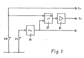
- FIG. 3 shows a circuit diagram for differentiating the signals emitted by the accident protection strip, firstly when hitting an obstacle and secondly when hitting the ground or the projection 27.
- Both the output circuit of the pressure switch 13 - normally closed contact DW - and the output circuit of the limit switch - Normally closed contact ZU - are designed as a monitoring-safe closed circuit.
- the output of the pressure switch is fed to an input S I of an evaluation circuit, not shown, which, via this input, receives an opening of the normally closed contact DW symbolizing the pressure switch as an alarm signal and triggers the usual switching off or switching over of the drive unit, if not at the same time at the second input S 2 of the evaluation circuit also occurs a signal.
- the output of the limit switch - normally closed contact - is fed to the input of a timer 24, the output of which is fed to the one input of a comparator circuit 25.
- the output signal of the pressure switch - normally closed contact DW - is fed to a second input of the comparator circuit 25 in parallel with S I.
- the comparator circuit is designed as an AND gate, ie a signal occurs at its output when signals are present at its two inputs at the same time.
- the output of the comparator circuit 25 is fed to the second input S 2 of the evaluation circuit via a signal conditioning circuit 26.
- the signal which occurs when the limit switch is actuated by opening the switch CLOSED is subject to an expansion by the timer switch 24, that is to say it occurs as soon as it occurs of the limit switch signal in the closed position of the door leaf a time during which a signal is present at the associated input of the comparator circuit 25.
- This timing can be generous Limits must be dimensioned and is preferably adjustable because the movement of the door leaf - especially when deliberately delayed entry into the closed position - can vary.
- the circuit should also be adaptable to different types of doors.
Landscapes
- Engineering & Computer Science (AREA)
- Structural Engineering (AREA)
- Architecture (AREA)
- Civil Engineering (AREA)
- Power-Operated Mechanisms For Wings (AREA)
- Fuses (AREA)
- Suspension Of Electric Lines Or Cables (AREA)
- Treatments For Attaching Organic Compounds To Fibrous Goods (AREA)
Claims (10)
Priority Applications (1)
| Application Number | Priority Date | Filing Date | Title |
|---|---|---|---|
| AT85110991T ATE42989T1 (de) | 1984-11-15 | 1985-08-30 | Unfallschutzleiste. |
Applications Claiming Priority (2)
| Application Number | Priority Date | Filing Date | Title |
|---|---|---|---|
| DE3441820 | 1984-11-15 | ||
| DE3441820A DE3441820C1 (de) | 1984-11-15 | 1984-11-15 | Unfallschutzleiste |
Publications (3)
| Publication Number | Publication Date |
|---|---|
| EP0182019A2 EP0182019A2 (fr) | 1986-05-28 |
| EP0182019A3 EP0182019A3 (en) | 1987-04-22 |
| EP0182019B1 true EP0182019B1 (fr) | 1989-05-10 |
Family
ID=6250412
Family Applications (1)
| Application Number | Title | Priority Date | Filing Date |
|---|---|---|---|
| EP85110991A Expired EP0182019B1 (fr) | 1984-11-15 | 1985-08-30 | Bande protectrice contre les accidents |
Country Status (3)
| Country | Link |
|---|---|
| EP (1) | EP0182019B1 (fr) |
| AT (1) | ATE42989T1 (fr) |
| DE (2) | DE3441820C1 (fr) |
Families Citing this family (8)
| Publication number | Priority date | Publication date | Assignee | Title |
|---|---|---|---|---|
| DE3633834A1 (de) * | 1985-12-18 | 1987-06-25 | Neukirchen W U H Gmbh Co Kg | Schliesskantensicherung fuer kraftbetaetigte fenster, tueren und tore |
| DE3545219A1 (de) * | 1985-12-20 | 1987-07-02 | Otto Sterkel Gmbh & Co | Steueranordnung fuer einen kraftbetaetigten oeffnungsabschluss, insbesondere torfluegel |
| SE469038B (sv) * | 1991-09-20 | 1993-05-03 | Cardo Door Ab | Anordning vid elektriskt drivna skjutportar |
| US5228492A (en) * | 1991-10-03 | 1993-07-20 | Jou Ming Sen | Electric rolling steel door safety stopping device |
| DE9301259U1 (de) * | 1993-01-29 | 1993-05-19 | Koch, Hubert, 85716 Unterschleißheim | Schutzkontaktvorrichtung für Schließkanten |
| US5839227A (en) * | 1997-07-29 | 1998-11-24 | Gardner; Andrew Joseph | Safety edge for an electrically operated door |
| DE19819704B4 (de) | 1998-05-02 | 2006-09-21 | Wabco Gmbh & Co.Ohg | Verfahren zur zyklischen Überprüfung von Überwachungseinrichtungen in Türschließanlagen |
| DE102006004791B4 (de) * | 2006-02-02 | 2013-11-28 | Roma Kg | Deckenlauftor |
Family Cites Families (2)
| Publication number | Priority date | Publication date | Assignee | Title |
|---|---|---|---|---|
| DE3028445C2 (de) * | 1980-07-26 | 1984-09-13 | Bayerische Motoren Werke AG, 8000 München | Sicherheitseinrichtung für motorisch bewegte Schließteile |
| DE3146489A1 (de) * | 1981-11-24 | 1983-06-01 | Karl-Heinz Dipl.-Ing. 4358 Haltern Paul | Sicherheitseinrichtung zur ueberwachung von kontaktschlaeuchen und schaltleisten |
-
1984
- 1984-11-15 DE DE3441820A patent/DE3441820C1/de not_active Expired - Lifetime
-
1985
- 1985-08-30 AT AT85110991T patent/ATE42989T1/de not_active IP Right Cessation
- 1985-08-30 EP EP85110991A patent/EP0182019B1/fr not_active Expired
- 1985-08-30 DE DE8585110991T patent/DE3570102D1/de not_active Expired
Also Published As
| Publication number | Publication date |
|---|---|
| DE3570102D1 (en) | 1989-06-15 |
| EP0182019A3 (en) | 1987-04-22 |
| EP0182019A2 (fr) | 1986-05-28 |
| ATE42989T1 (de) | 1989-05-15 |
| DE3441820C1 (de) | 1990-12-06 |
Similar Documents
| Publication | Publication Date | Title |
|---|---|---|
| AT414005B (de) | Türspaltüberwachung | |
| EP0344401B1 (fr) | Dispositif de sécurité pour une vitre de véhicule automatique | |
| DE3921641C2 (fr) | ||
| EP2404859B1 (fr) | Dispositif de surveillance pour sécuriser un élément entraîné | |
| EP0182019B1 (fr) | Bande protectrice contre les accidents | |
| DE7735191U1 (de) | Rolladen | |
| EP0232866A2 (fr) | Dispositif de commande de l'ouverture et/ou fermeture de portes à mouvement rapide | |
| EP2236732B1 (fr) | Porte | |
| EP2880234A1 (fr) | Dispositif de surveillance et de commande pour une unité porte | |
| DE7115862U (de) | Kontaktgeber fuer sicherheitseinrichtungen an motorisch verschliessbaren oeffnungen im aufbau von kraftfahrzeugen, vorzugsweise an fahrzeugfenstern | |
| DE19847080C2 (de) | Verstelleinrichtung für Verstellteile in Kraftfahrzeugen | |
| DE202008009320U1 (de) | Überwachungs- und Diagnoseeinheit | |
| EP2589991B1 (fr) | Barrette profilée de sécurité dotée d'une grille lumineuse | |
| EP0980460A1 (fr) | Fenetre ou porte pour batiment | |
| DE102006008513A1 (de) | Sensor-Überwachungseinrichtung | |
| EP0091607A2 (fr) | Dispositif de sécurité pour éléments de fermeture mobiles, en particulier pour volets de protection de machines d'usinage | |
| DE19533153C2 (de) | Schiebetür mit Notöffnungs- oder Notschließeinrichtung | |
| DE19958305C2 (de) | Überwachung von Fingerschutzleisten für Fahrzeugtüren | |
| DE4118782A1 (de) | Steuerungseinrichtung fuer tore | |
| DE29623251U1 (de) | Rolltor | |
| DE3411198C2 (fr) | ||
| DE9302676U1 (de) | Lichtschrankenanordnung, z.B. für ein KFZ-Seitenfenster | |
| DE9418885U1 (de) | Sicherungseinrichtung für die Schließkante eines angetriebenen Durchfahrtverschlusses | |
| DE19819704B4 (de) | Verfahren zur zyklischen Überprüfung von Überwachungseinrichtungen in Türschließanlagen | |
| DE102004053820B4 (de) | Sensoranordnung für automatische Türanlagen |
Legal Events
| Date | Code | Title | Description |
|---|---|---|---|
| PUAI | Public reference made under article 153(3) epc to a published international application that has entered the european phase |
Free format text: ORIGINAL CODE: 0009012 |
|
| AK | Designated contracting states |
Kind code of ref document: A2 Designated state(s): AT BE CH DE FR GB IT LI LU NL SE |
|
| RBV | Designated contracting states (corrected) |
Designated state(s): AT BE CH DE FR GB IT LI NL SE |
|
| PUAL | Search report despatched |
Free format text: ORIGINAL CODE: 0009013 |
|
| AK | Designated contracting states |
Kind code of ref document: A3 Designated state(s): AT BE CH DE FR GB IT LI NL SE |
|
| 17P | Request for examination filed |
Effective date: 19871021 |
|
| 17Q | First examination report despatched |
Effective date: 19880826 |
|
| GRAA | (expected) grant |
Free format text: ORIGINAL CODE: 0009210 |
|
| AK | Designated contracting states |
Kind code of ref document: B1 Designated state(s): AT BE CH DE FR GB IT LI NL SE |
|
| REF | Corresponds to: |
Ref document number: 42989 Country of ref document: AT Date of ref document: 19890515 Kind code of ref document: T |
|
| REF | Corresponds to: |
Ref document number: 3570102 Country of ref document: DE Date of ref document: 19890615 |
|
| ET | Fr: translation filed | ||
| ITF | It: translation for a ep patent filed | ||
| GBT | Gb: translation of ep patent filed (gb section 77(6)(a)/1977) | ||
| PLBI | Opposition filed |
Free format text: ORIGINAL CODE: 0009260 |
|
| PLBI | Opposition filed |
Free format text: ORIGINAL CODE: 0009260 |
|
| 26 | Opposition filed |
Opponent name: NOMAFA AB Effective date: 19900201 |
|
| 26 | Opposition filed |
Opponent name: CRAWFORD DOOR AB Effective date: 19900207 Opponent name: NOMAFA AB Effective date: 19900201 |
|
| NLR1 | Nl: opposition has been filed with the epo |
Opponent name: NOMAFA AB |
|
| NLR1 | Nl: opposition has been filed with the epo |
Opponent name: CRAWFORD DOOR AB. |
|
| PLBN | Opposition rejected |
Free format text: ORIGINAL CODE: 0009273 |
|
| STAA | Information on the status of an ep patent application or granted ep patent |
Free format text: STATUS: OPPOSITION REJECTED |
|
| 27O | Opposition rejected |
Effective date: 19930328 |
|
| NLR2 | Nl: decision of opposition | ||
| ITTA | It: last paid annual fee | ||
| EAL | Se: european patent in force in sweden |
Ref document number: 85110991.8 |
|
| REG | Reference to a national code |
Ref country code: CH Ref legal event code: PFA Free format text: HOERMANN KG ANTRIEBS- U. STEUERUNGSTECHNIK TRANSFER- MARANTEC ANTRIEBS- UND STEUERUNGSTECHNIK GMBH & CO. KG. |
|
| NLT1 | Nl: modifications of names registered in virtue of documents presented to the patent office pursuant to art. 16 a, paragraph 1 |
Owner name: MARANTEC ANTRIEBS- UND STEUERUNGSTECHNIK GMBH & CO |
|
| REG | Reference to a national code |
Ref country code: GB Ref legal event code: IF02 |
|
| PGFP | Annual fee paid to national office [announced via postgrant information from national office to epo] |
Ref country code: GB Payment date: 20020722 Year of fee payment: 18 |
|
| PGFP | Annual fee paid to national office [announced via postgrant information from national office to epo] |
Ref country code: AT Payment date: 20020819 Year of fee payment: 18 |
|
| PGFP | Annual fee paid to national office [announced via postgrant information from national office to epo] |
Ref country code: SE Payment date: 20020820 Year of fee payment: 18 Ref country code: NL Payment date: 20020820 Year of fee payment: 18 Ref country code: FR Payment date: 20020820 Year of fee payment: 18 Ref country code: BE Payment date: 20020820 Year of fee payment: 18 |
|
| PGFP | Annual fee paid to national office [announced via postgrant information from national office to epo] |
Ref country code: DE Payment date: 20020829 Year of fee payment: 18 |
|
| PGFP | Annual fee paid to national office [announced via postgrant information from national office to epo] |
Ref country code: CH Payment date: 20020903 Year of fee payment: 18 |
|
| PG25 | Lapsed in a contracting state [announced via postgrant information from national office to epo] |
Ref country code: GB Free format text: LAPSE BECAUSE OF NON-PAYMENT OF DUE FEES Effective date: 20030830 Ref country code: AT Free format text: LAPSE BECAUSE OF NON-PAYMENT OF DUE FEES Effective date: 20030830 |
|
| PG25 | Lapsed in a contracting state [announced via postgrant information from national office to epo] |
Ref country code: SE Free format text: LAPSE BECAUSE OF NON-PAYMENT OF DUE FEES Effective date: 20030831 Ref country code: LI Free format text: LAPSE BECAUSE OF NON-PAYMENT OF DUE FEES Effective date: 20030831 Ref country code: CH Free format text: LAPSE BECAUSE OF NON-PAYMENT OF DUE FEES Effective date: 20030831 Ref country code: BE Free format text: LAPSE BECAUSE OF NON-PAYMENT OF DUE FEES Effective date: 20030831 |
|
| BERE | Be: lapsed |
Owner name: *HORMANN K.G. ANTRIEBS- UND STEUERUNGSTECHNIK Effective date: 20030831 |
|
| PG25 | Lapsed in a contracting state [announced via postgrant information from national office to epo] |
Ref country code: NL Free format text: LAPSE BECAUSE OF NON-PAYMENT OF DUE FEES Effective date: 20040301 |
|
| PG25 | Lapsed in a contracting state [announced via postgrant information from national office to epo] |
Ref country code: DE Free format text: LAPSE BECAUSE OF NON-PAYMENT OF DUE FEES Effective date: 20040302 |
|
| EUG | Se: european patent has lapsed | ||
| REG | Reference to a national code |
Ref country code: CH Ref legal event code: PL |
|
| GBPC | Gb: european patent ceased through non-payment of renewal fee | ||
| PG25 | Lapsed in a contracting state [announced via postgrant information from national office to epo] |
Ref country code: FR Free format text: LAPSE BECAUSE OF NON-PAYMENT OF DUE FEES Effective date: 20040430 |
|
| NLV4 | Nl: lapsed or anulled due to non-payment of the annual fee |
Effective date: 20040301 |
|
| REG | Reference to a national code |
Ref country code: FR Ref legal event code: ST |