EP0182807B1 - Detecteur de glace non-intrusif du type a membrane - Google Patents
Detecteur de glace non-intrusif du type a membrane Download PDFInfo
- Publication number
- EP0182807B1 EP0182807B1 EP85902228A EP85902228A EP0182807B1 EP 0182807 B1 EP0182807 B1 EP 0182807B1 EP 85902228 A EP85902228 A EP 85902228A EP 85902228 A EP85902228 A EP 85902228A EP 0182807 B1 EP0182807 B1 EP 0182807B1
- Authority
- EP
- European Patent Office
- Prior art keywords
- ice
- tube
- diaphragm
- natural frequency
- center portion
- Prior art date
- Legal status (The legal status is an assumption and is not a legal conclusion. Google has not performed a legal analysis and makes no representation as to the accuracy of the status listed.)
- Expired
Links
- 239000012528 membrane Substances 0.000 title 1
- 230000015572 biosynthetic process Effects 0.000 claims description 7
- 230000001419 dependent effect Effects 0.000 claims description 3
- 230000005284 excitation Effects 0.000 abstract description 3
- 230000035508 accumulation Effects 0.000 description 21
- 238000009825 accumulation Methods 0.000 description 21
- 239000004744 fabric Substances 0.000 description 5
- 238000006073 displacement reaction Methods 0.000 description 4
- 230000000694 effects Effects 0.000 description 3
- 239000000463 material Substances 0.000 description 3
- 239000000523 sample Substances 0.000 description 3
- 239000002184 metal Substances 0.000 description 2
- 229910052751 metal Inorganic materials 0.000 description 2
- 230000002093 peripheral effect Effects 0.000 description 2
- 239000004033 plastic Substances 0.000 description 2
- 229920003023 plastic Polymers 0.000 description 2
- RYGMFSIKBFXOCR-UHFFFAOYSA-N Copper Chemical compound [Cu] RYGMFSIKBFXOCR-UHFFFAOYSA-N 0.000 description 1
- 229920004943 Delrin® Polymers 0.000 description 1
- 230000003213 activating effect Effects 0.000 description 1
- 238000005452 bending Methods 0.000 description 1
- 229910052802 copper Inorganic materials 0.000 description 1
- 239000010949 copper Substances 0.000 description 1
- 239000013078 crystal Substances 0.000 description 1
- 238000001514 detection method Methods 0.000 description 1
- 239000004417 polycarbonate Substances 0.000 description 1
- 229920000515 polycarbonate Polymers 0.000 description 1
- 230000035945 sensitivity Effects 0.000 description 1
- 238000007493 shaping process Methods 0.000 description 1
- 238000004904 shortening Methods 0.000 description 1
Images
Classifications
-
- G—PHYSICS
- G01—MEASURING; TESTING
- G01N—INVESTIGATING OR ANALYSING MATERIALS BY DETERMINING THEIR CHEMICAL OR PHYSICAL PROPERTIES
- G01N29/00—Investigating or analysing materials by the use of ultrasonic, sonic or infrasonic waves; Visualisation of the interior of objects by transmitting ultrasonic or sonic waves through the object
- G01N29/04—Analysing solids
- G01N29/12—Analysing solids by measuring frequency or resonance of acoustic waves
-
- B—PERFORMING OPERATIONS; TRANSPORTING
- B64—AIRCRAFT; AVIATION; COSMONAUTICS
- B64D—EQUIPMENT FOR FITTING IN OR TO AIRCRAFT; FLIGHT SUITS; PARACHUTES; ARRANGEMENT OR MOUNTING OF POWER PLANTS OR PROPULSION TRANSMISSIONS IN AIRCRAFT
- B64D15/00—De-icing or preventing icing on exterior surfaces of aircraft
- B64D15/20—Means for detecting icing or initiating de-icing
-
- G—PHYSICS
- G01—MEASURING; TESTING
- G01W—METEOROLOGY
- G01W1/00—Meteorology
-
- G—PHYSICS
- G01—MEASURING; TESTING
- G01N—INVESTIGATING OR ANALYSING MATERIALS BY DETERMINING THEIR CHEMICAL OR PHYSICAL PROPERTIES
- G01N2291/00—Indexing codes associated with group G01N29/00
- G01N2291/02—Indexing codes associated with the analysed material
- G01N2291/025—Change of phase or condition
- G01N2291/0251—Solidification, icing, curing composites, polymerisation
Definitions
- the invention relates to an ice detector.
- a vibrating type ice detector which changes natural frequency upon accumulation of ice on a sensing probe is shown in US-A-3341835.
- This detector has a tube supported substantially at a midpoint, which forms a node of vibration, and the tube is driven with a coil to vibrate axially between the node and its opposite ends at its natural frequency.
- the vibration is a minute lengthening and shortening of the two tube sections between the node and respective ends.
- the frequency of vibration is sensed by a feedback coil. Ice accumulation on the exposed portion of the probe causes a change in natural frequency, as opposed to a dampening of amplitude of vibration, and this change in frequency is sensed as an indication of ice accumulation.
- the circuitry used for driving the tube to its natural frequency that is setting up longitudinal vibration between a mounting node and opposite ends of the tube, operates on the same principle as does the detector of the present invention and the principle of sensing the change in frequency caused by ice accumulation is also the same.
- the probe protrudes substantially into the air stream, causing drag and the possibility of mechanical damage, and also forming a radar reflective target.
- a mechanical displacement type ice detector sensor using a diaphragm is disclosed in US-A-2414756.
- the diaphragm does not protrude into the air stream, as such, but the sensing is done by driving the diaphragm to deflect in opposite directions. Operation is carried out by measuring the dampening of displacement occasioned by ice accumulation.
- Frequency sensing is not used, and the structure has to be quite large so that there is a substantial change in mass when ice accumulates on the diaphragm before accurate output readings can be obtained.
- This detector thus has the problem of large size and low sensitivity to small accumulations of ice, and there is a requirement that there be substantial displacement of the diaphragm.
- shaping this type of diaphragm to conform to the shape of a surface in which the ice detector is mounted is not practical in that the diaphragm has to be substantially planar for operation.
- a frequency sensitive ice detector which has a large area, tapered disc covered with a fabric that is exposed to the formation of ice is disclosed in US-A-2800647.
- a stack of crystal plates forms a vibrating column supporting the disc, and the changes in resonant frequency of the vibrating column are sensed for determining ice accumulation.
- the fabric outer cover forms an ice collecting surface, and the mass of ice on the surface is sensed by the vibrating system, due to natural frequency changes because of the change in mass on the fabric.
- the fabric area in this detector can form a smooth continuation of adjacent portions of an extended mounting surface.
- the sensor requires quite a large surface area; the use of fabric, which is not suitable for high performance aircraft; and a complex mounting assembly.
- US-A-3240054 discloses an ice detector that has a surface that collects ice, and depends upon the vibrating of an elastic diaphragm which changes in stiffness upon ice accumulation.
- the detector depends on the flexural stiffness of the entire diaphragm and diaphragms cannot be shaped to conform to a curved surface. This document does, however, teach that the stiffness of ice can change resonant frequencies of elastic members that are being used for ice detectors.
- an ice detector comprising a diaphragm member for exposure to an air stream in which ice is to be detected, said diaphragm member having a center portion, and outer edge support portion, and a flexible wall portion extending between the outer edge support portion and the center portion, said flexible wall portion permitting deflecting movement of the center portion in the direction generally normal to the diaphragm member; means connected to the center portion to vibrate the center portion and having a mass that is selected to cause the natural frequency of vibration to be dependent upon the flexibility of said flexible wall portion between the center portion and the outer support edge portion of said diaphragm member; and means to sense changes in natural frequency of said means to vibrate upon change in flexibility of said flexible wall portion due to stiffness of ice accumulating on said diaphragm member.
- the invention can have a small exposed diaphragm surface which can be conformed to a curved shape that forms a continuation of a surface on which ice formation is to be detected.
- the surface used for sensing ice does not intrude into the air stream and eliminates additional drag. The sensor is then less likely to be sensed by radar.
- the detector of the invention permits sensing of small accumulations of ice, because the ice is stiff and causes a substantial change in spring constant of the flexible wall portion, which alters the natural frequency of the vibrating means.
- the detector can be de-iced conventionally, and because it is small and the shape of the center portion is alterable, the diaphragm can be madeto conform to contours or other configurations of an airfoil or other surface on which the detector is to be mounted.
- the detector has a wide range of uses including meteorological devices, air vehicles and commercial devices where formation of ice is to be sensed.
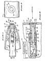
- An ice detector indicated generally at 10 is mounted onto a surface, such as a wing 11 on which ice may accumulate, and where such accumulation of ice is to be sensed.
- the mounting surface may be any surface in any location where ice will form.
- Air vehicle surfaces, and turbine inlets are two types of surfaces where the detector finds use.
- the ice detector 10 includes an outer housing 12 which is attached with respect to the wing 11 with suitable supports illustrated schematically at 13, and which has an end member 14 mounted in an opening in the surface, such as a wing, and tightly sealed around its periphery with respect thereto.
- the leading end of the ice detector end member 14 can be contoured to conform to the shape of the surface on which it is mounted.
- the housing 12 may be made of either a suitable plastics or metal and includes an enlarged section 15, and a smaller section 16 which is attached to the end portion 14.
- the enlarged section 15 mounts a coil tube 19 in which a drive coil 20 is mounted adjacent one end.
- a sensing or feedback coil 21 is mounted coaxial with the coil 20 in the coil tube 19 and is spaced therefrom by a washer 22, which may be made of suitable material such as copper, to effectively magnetically decouple the two coils.
- Suitable lead wires 23 lead from the coils to terminals 24, and the terminals are connected to excitation and sensing circuitry of conventional design indicated at 25.
- this sensing circuitry there are means to determine changes in natural frequency indicated at 26 which will control powerto a heater wire shown at 27 in the outer end member 14, to remove ice that has accumulated after the ice has accumulated on the sensor sufficiently to be detected.
- the heater 27 causes previously accumulated ice to melt and fall off. The heater then is shut off so that the ice detector is capable of detecting continuing or recurring icing conditions.
- a mounting receptacle 28 formed on housing 12 mounts a permanent magnet 29 adjacent drive coil 20 and feedback coil 21.
- a support 30 is mounted at a soulder 31 formed in the housing 12, between the sections 15 and 16.
- Support 30 is an annular washer to which a vibrating tube 32 is fixedly attached on the inner surface of support30.
- the support 30 is a vibration termination support, forming a node on the tube 32.
- the tube 32 is made of a suitable magneto strictive material capable of being driven by the drive coil 20, for vibration in longitudinal direction, that is along the axis of tube 32.
- Permanent magnet 29 elongates tube 32 such that when tube 32 is driven by drive coil 20, the vibration is substantially sinusoidal because tube 32 is not compressed, but vibrated about a state of elongation.
- a first section 33 of the tube 32 extends from the support 30 to the member 14, and a second section 34 of the tube extends from the support 30 in opposite direction toward an open end of the tube indicated at 34A.
- the two tube sections vibrate from the center mounting plane defined by support 30 outwardly under excitation from drive coil 20 acting directly on tube section 34.
- the tube sections vibrate by elongating and compressing from an elongated state slightly in the axial direction.
- the support 30 forms a vibration node along the diametral plane passing through the support 30.
- the first outer end tube section 33 is coupled in a suitable manner to a vibrating diaphragm 35 formed as part of the member 14, and having a central portion 36 forming a sleeve 40 that fits inside the tube section 33.
- the sleeve 40 is fixed to the tube section 33 in a suitable manner so axial vibration of the tube section causes deflection of the central portion 36 of diaphragm 35.
- the end of tube section 40 is terminated along a plane perpendicular to its axis and is not curved or shaped to conform the outer surface of the wing.
- the central portion 36 of the diaphragm 35 is therefore supported for movement with the tube section 33.
- the central portion 36 is connected to an outer peripheral support portion 37 of the diaphragm 35 through an annular spring or flexible connector portion 38 which is of reduced thickness from the center portion 36.
- the flexible connector portion 38 forms an annular spring hinge all around the diaphragm center portion 36 in the preferred embodiment, to spring load the center portion 36 relative to its peripheral support portion 37 so that deflecting movement of the center portion of the diaphragm will be under a spring load by bending the spring wall section 38.
- the flexible connector portion 38 may form a flexible annular hinge around the diaphragm center portion 36 to provide for free deflecting movement of the center portion of the diaphragm, rather than providing any spring load.
- the diaphragm flexible wall section 38 is preferably in the range of 0.13 mm (.005 inches) to 6.35 mm (.025 inches) thick, having a radial length of 0.25 to 1.3 (.010 to .050). It may be of a suitable light weight elastic non radar reflective plastic material such as a polycarbonate or Delrin, or if desired, it may be made of a metal.
- the ice detector When the ice detector is operated, it is driven by the drive coil 20 to its natural frequency so that as the tube sections 33 and 34 vibrate longitudinally the tube sections extend and contract in length from the diametral plane at the support 30, which forms the node of vibration. This vibration in turn will deflect the diaphragm central portion 36 at the natural frequency of the assembly of the tube section 33.
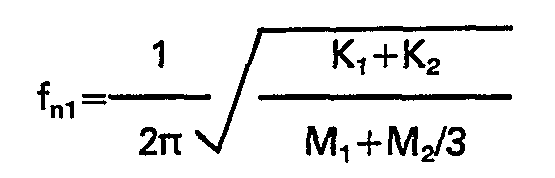
- the natural frequency of the tube section 33 depends upon the spring constant of the flexible wall portion 38 as well as the spring constant of the tube section 33 and the masses of the tube section 33 and the central portion 36 of the diaphragm 35.
- the natural frequency of the two tube sections 33 and 34 should be approximately equal, and when the drive coil drives the tube section 33 at its natural frequency, as sensed through the feedback coil and conventional circuitry, the tube section 34 near the coils vibrates longitudinally, and this vibration is transmitted across the support 30 at the tube node, to the tube section 33 to the sensing surface comprising flexible wall portion 38.
- the stiffness of the flexible wall portion 38 increases, and while the mass M 1 also increases, the ice is very stiff so that the effect of the stiffness of the wall portion 38 increases at a greater rate than the effect of mass M 1 and the natural frequency f n1 increases.
- the feedback coil 21 senses the change in natural frequency and the shift in frequency is sensed at the external circuit 25 to provide an indication that ice is forming.
- the circuit output can be used for activating warning signals or for turning on remote deicing equipment the rate of icing also can be determined by sensing the changes in. natural frequency during an elapsed time.
- the circuit can be used for initializing power for energizing the heater 27 for deicing the ice detector.
- the heater 27 operates substantially as described in U.S. Patent No. 3,341,835.
- the natural frequency of the tube section 33 and diaphragm 35 as seen in Equation 1 increases with increase in the spring constant of the flexible wall portion 38 caused by ice accumulation. Ice accumulation on diaphragm 35 increases the mass of the center diaphragm portion 36, which by itself tends to cause a slight decrease in natural frequency.
- the modulus of elasticity of ice shortly after formation is on the order 700 bar (1x10 6 psi) which leads to significant changes in spring constants when compared to the spring constants of tube section 33 and flexible wall portion 38.
- Increases in spring constant cause the natural frequency to increase.
- the natural frequency increases with ice accumulation, thus confirming that the tendency to increase in natural frequency caused by increased spring constant is more significant than the tendency to decrease in natural frequency caused by increased mass.
- the density of ice is approximately 9 Pa/cm (.0324 Ib/in 3 ).
- the mass of ice is approximately 0.04 g (.00009 lbs).
- Equation 1 where M 2 , the mass of the tube section 33 extending from the support 30 to the diaphragm portion 36 is approximately 14 g (.003 lbs), and the mass of the center diaphragm portion 36 is approximately 1.4 g (.00030 lbs), the percentage change in the denominator of Equation 1 due to increase in mass from ice accumulation is less than 7%.
- the spring constant K 1 of the tube section 33 is approximately 60000 kg/cm (340,000 Ib/in) and that of the flexible wall portion 38 is approximately 800 kg/cm (4600 Ib/in).
- the percent change in the numerator of Equation 1 due to an accumulation of 0.6 cm (.025 in) of ice, is greaterthan 40%.
- the change in spring constant due to ice accumulation has a much greater effect on the natural frequency than the mass of the accumulated ice.
- the detector is sensitive to small accumulations of ice, and is not dependent upon substantial mass changes. This makes the detector adaptable to be small and non-intrusive. Accumulation of ice on the center diaphragm portion 36 does not significantly affect the frequency of vibration.
- the center diaphragm portion may be shaped to conform to the surface of the member to which it is mounted such that continuity of radar profile and aerodynamic surface is maintained.
Landscapes
- Physics & Mathematics (AREA)
- Environmental & Geological Engineering (AREA)
- Engineering & Computer Science (AREA)
- Life Sciences & Earth Sciences (AREA)
- Pathology (AREA)
- Health & Medical Sciences (AREA)
- Biochemistry (AREA)
- General Health & Medical Sciences (AREA)
- General Physics & Mathematics (AREA)
- Immunology (AREA)
- Chemical & Material Sciences (AREA)
- Analytical Chemistry (AREA)
- Aviation & Aerospace Engineering (AREA)
- Acoustics & Sound (AREA)
- Atmospheric Sciences (AREA)
- Biodiversity & Conservation Biology (AREA)
- Ecology (AREA)
- Environmental Sciences (AREA)
- Geophysics And Detection Of Objects (AREA)
- Investigating Or Analyzing Materials By The Use Of Ultrasonic Waves (AREA)
Abstract
Claims (9)

Applications Claiming Priority (2)
| Application Number | Priority Date | Filing Date | Title |
|---|---|---|---|
| US606663 | 1984-05-03 | ||
| US06/606,663 US4611492A (en) | 1984-05-03 | 1984-05-03 | Membrane type non-intrusive ice detector |
Publications (3)
| Publication Number | Publication Date |
|---|---|
| EP0182807A1 EP0182807A1 (fr) | 1986-06-04 |
| EP0182807A4 EP0182807A4 (fr) | 1986-10-02 |
| EP0182807B1 true EP0182807B1 (fr) | 1989-06-14 |
Family
ID=24428936
Family Applications (1)
| Application Number | Title | Priority Date | Filing Date |
|---|---|---|---|
| EP85902228A Expired EP0182807B1 (fr) | 1984-05-03 | 1985-04-05 | Detecteur de glace non-intrusif du type a membrane |
Country Status (6)
| Country | Link |
|---|---|
| US (1) | US4611492A (fr) |
| EP (1) | EP0182807B1 (fr) |
| JP (1) | JPH0758248B2 (fr) |
| CA (1) | CA1209224A (fr) |
| DE (1) | DE3571080D1 (fr) |
| WO (1) | WO1985005185A1 (fr) |
Families Citing this family (37)
| Publication number | Priority date | Publication date | Assignee | Title |
|---|---|---|---|---|
| FR2605402B1 (fr) * | 1986-10-15 | 1991-07-26 | Onera (Off Nat Aerospatiale) | Dispositif de la detection de la presence de givre et/ou de mesure de l'epaisseur de givre par ultra-sons et sonde de givrage utilisable dans un tel dispositif |
| US4891628A (en) * | 1988-12-29 | 1990-01-02 | Leonard Zuckerman | Environmental matter detection system |
| US5398547A (en) * | 1989-01-10 | 1995-03-21 | Innovative Dynamics, Inc. | Apparatus for measuring ice distribution profiles |
| US5195046A (en) * | 1989-01-10 | 1993-03-16 | Gerardi Joseph J | Method and apparatus for structural integrity monitoring |
| US5206806A (en) * | 1989-01-10 | 1993-04-27 | Gerardi Joseph J | Smart skin ice detection and de-icing system |
| US5117687A (en) * | 1990-01-11 | 1992-06-02 | Gerardi Joseph J | Omnidirectional aerodynamic sensor |
| US5187980A (en) * | 1990-05-31 | 1993-02-23 | The United States Of America As Represented By The United States Department Of Energy | Method and apparatus for acoustic plate mode liquid-solid phase transition detection |
| US6052056A (en) * | 1996-04-26 | 2000-04-18 | Icg Technologies, Llc | Substance detection system and method |
| US6301967B1 (en) | 1998-02-03 | 2001-10-16 | The Trustees Of The Stevens Institute Of Technology | Method and apparatus for acoustic detection and location of defects in structures or ice on structures |
| US6269320B1 (en) | 1998-11-19 | 2001-07-31 | Rosemount Aerospace, Inc. | Supercooled large droplet ice detector |
| US6140942A (en) * | 1999-06-25 | 2000-10-31 | Board Of Trustees Of The University Of Illinois | Aircraft surface contamination sensing system using control surface hinge moment measurements |
| US6320511B1 (en) * | 2000-11-28 | 2001-11-20 | Rosemount Aerospace Inc. | Ice detector configuration for improved ice detection at near freezing conditions |
| CA2452623A1 (fr) | 2001-06-29 | 2003-01-09 | Rosemount Aerospace Inc. | Detecteur de givre permettant de detecter de grosses gouttelettes surfondues |
| US7014357B2 (en) | 2002-11-19 | 2006-03-21 | Rosemount Aerospace Inc. | Thermal icing conditions detector |
| US7175136B2 (en) | 2003-04-16 | 2007-02-13 | The Boeing Company | Method and apparatus for detecting conditions conducive to ice formation |
| JP4424617B2 (ja) * | 2003-08-20 | 2010-03-03 | ザ・ボーイング・カンパニー | 着氷状態を検出するための方法及び装置 |
| US20050230553A1 (en) | 2004-03-31 | 2005-10-20 | Rosemount Aerospace Inc. | Ice detector for improved ice detection at near freezing condition |
| US7104502B2 (en) * | 2004-03-31 | 2006-09-12 | Rosemount Aerospace Inc. | Ice detector for improved ice detection at near freezing condition |
| US7031871B2 (en) * | 2004-06-04 | 2006-04-18 | Rosemount Aerospace, Inc. | Sensor assembly for determining total temperature, static temperature and Mach number |
| US7331421B2 (en) | 2005-03-30 | 2008-02-19 | The Boeing Company | Flow restrictors for aircraft inlet acoustic treatments, and associated systems and methods |
| US9002484B2 (en) * | 2006-12-01 | 2015-04-07 | The Invention Science Fund I Llc | System and method for deforming surfaces |
| US8783337B2 (en) * | 2006-12-01 | 2014-07-22 | The Invention Science Fund I Llc | System for changing the convective heat transfer coefficient for a surface |
| US20080257033A1 (en) * | 2007-04-20 | 2008-10-23 | Shadin, L.P. | Ice detection |
| FR2931454B1 (fr) * | 2008-05-20 | 2010-12-03 | Airbus France | Element de structure d'un aeronef ayant une partie creuse et indicateur de formation de glace dans une telle partie creuse |
| BR102013010356A2 (pt) | 2012-04-27 | 2015-06-30 | Goodrich Corp | Sistema de proteção contra gelo |
| US10450075B2 (en) | 2017-08-28 | 2019-10-22 | Rosemount Aerospace Inc. | Method of making a magnetostrictive oscillator ice rate sensor probe |
| WO2019222598A1 (fr) | 2018-05-17 | 2019-11-21 | Rosemount Inc. | Élément de mesure et dispositif de mesure le comprenant |
| AU2019310032B2 (en) | 2018-07-24 | 2023-03-16 | Deep Science, Llc | Systems and methods for active control of surface drag |
| CN113039367B (zh) | 2018-11-06 | 2023-08-04 | 深度科学有限责任公司 | 使用壁耦合主动控制表面曳力的系统和方法 |
| US11744157B2 (en) | 2018-11-30 | 2023-08-29 | Deep Science, Llc | Systems and methods of active control of surface drag using selective wave generation |
| KR102313874B1 (ko) * | 2019-11-15 | 2021-10-18 | 주식회사 에그 (Egg) | 결빙감지장치 |
| US11905983B2 (en) | 2020-01-23 | 2024-02-20 | Deep Science, Llc | Systems and methods for active control of surface drag using electrodes |
| WO2021150755A1 (fr) * | 2020-01-23 | 2021-07-29 | Deep Science, Llc | Systèmes et procédés de commande active de traînée de surface à l'aide d'un actionnement intermittent ou variable |
| US11802756B2 (en) | 2020-08-18 | 2023-10-31 | Steven R. Weeres | Ice thickness transducer |
| US11466709B2 (en) | 2021-02-17 | 2022-10-11 | Deep Science, Llc | In-plane transverse momentum injection to disrupt large-scale eddies in a turbulent boundary layer |
| US20220396361A1 (en) | 2021-06-10 | 2022-12-15 | Goodrich Corporation | Mechanical ice protection system for aerodynamic surfaces |
| EP4446229A1 (fr) | 2023-04-14 | 2024-10-16 | Goodrich Corporation | Système mécanique de protection contre la glace pour surfaces aérodynamiques |
Family Cites Families (5)
| Publication number | Priority date | Publication date | Assignee | Title |
|---|---|---|---|---|
| GB506843A (en) * | 1938-01-12 | 1939-06-06 | Rudolf Goldschmidt | Means for indicating ice formation |
| US2414756A (en) * | 1943-05-07 | 1947-01-21 | Honeywell Regulator Co | Condition responsive device |
| US2800647A (en) * | 1955-03-18 | 1957-07-23 | Cievite Corp | Ice detector |
| US3240054A (en) * | 1962-12-24 | 1966-03-15 | Gabb Special Products Inc | Ice detector |
| US3341835A (en) * | 1964-11-05 | 1967-09-12 | Rosemount Eng Co Ltd | Ice detector |
-
1984
- 1984-05-03 US US06/606,663 patent/US4611492A/en not_active Expired - Lifetime
-
1985
- 1985-04-05 EP EP85902228A patent/EP0182807B1/fr not_active Expired
- 1985-04-05 DE DE8585902228T patent/DE3571080D1/de not_active Expired
- 1985-04-05 JP JP60501904A patent/JPH0758248B2/ja not_active Expired - Fee Related
- 1985-04-05 WO PCT/US1985/000594 patent/WO1985005185A1/fr not_active Ceased
- 1985-04-16 CA CA000479306A patent/CA1209224A/fr not_active Expired
Also Published As
| Publication number | Publication date |
|---|---|
| JPH0758248B2 (ja) | 1995-06-21 |
| EP0182807A4 (fr) | 1986-10-02 |
| DE3571080D1 (de) | 1989-07-20 |
| US4611492A (en) | 1986-09-16 |
| WO1985005185A1 (fr) | 1985-11-21 |
| EP0182807A1 (fr) | 1986-06-04 |
| CA1209224A (fr) | 1986-08-05 |
| JPS61502070A (ja) | 1986-09-18 |
Similar Documents
| Publication | Publication Date | Title |
|---|---|---|
| EP0182807B1 (fr) | Detecteur de glace non-intrusif du type a membrane | |
| US4553137A (en) | Non-intrusive ice detector | |
| US5670709A (en) | Transducer for the measurement of attributes of flowable media | |
| US4811595A (en) | System for monitoring fluent material within a container | |
| US4312235A (en) | Sensor and meter for measuring the mass flow of a fluid stream | |
| EP0221467B1 (fr) | Transducteur du type vibrant | |
| US6044699A (en) | Gauge for accurately measuring precipitation | |
| EP1376087A1 (fr) | Détecteur à microstructure intégrée à résonance à haute temperature | |
| JPH11248725A (ja) | タイヤ回転センサ | |
| US4351192A (en) | Fluid flow velocity sensor using a piezoelectric element | |
| US4074565A (en) | Vibratory-wire strain gage | |
| US6378377B2 (en) | Acoustic reflector attachment compatible with native aircraft structure | |
| EP0629839A1 (fr) | Dispositif d'ajustement d'un gyroscope à vibration | |
| CA1290593C (fr) | Systeme de montage et d'isolation d'un capteur de temperature a diapason | |
| US4653325A (en) | Gyro apparatus | |
| US3520193A (en) | Vibrating wire gyroscope | |
| US6907785B1 (en) | Diagnostic sensor | |
| GB2175090A (en) | Mounting of surface acoustic wave devices | |
| US3382722A (en) | Indicating instrument having vibrator for removing effects of static friction | |
| JPH03108628A (ja) | 振動梁型圧力センサ | |
| JPH073332Y2 (ja) | 超音波風向風速温度計 | |
| SU762332A1 (ru) | Вибрационный датчик обле- ( iденения | |
| SU1107062A1 (ru) | Измеритель ускорени | |
| SU1134891A1 (ru) | Частотный датчик давлени | |
| US4047428A (en) | Force measuring transducer with frequency output signal |
Legal Events
| Date | Code | Title | Description |
|---|---|---|---|
| PUAI | Public reference made under article 153(3) epc to a published international application that has entered the european phase |
Free format text: ORIGINAL CODE: 0009012 |
|
| 17P | Request for examination filed |
Effective date: 19851223 |
|
| AK | Designated contracting states |
Kind code of ref document: A1 Designated state(s): CH DE FR GB LI |
|
| A4 | Supplementary search report drawn up and despatched |
Effective date: 19861002 |
|
| 17Q | First examination report despatched |
Effective date: 19880831 |
|
| GRAA | (expected) grant |
Free format text: ORIGINAL CODE: 0009210 |
|
| AK | Designated contracting states |
Kind code of ref document: B1 Designated state(s): CH DE FR GB LI |
|
| PG25 | Lapsed in a contracting state [announced via postgrant information from national office to epo] |
Ref country code: LI Effective date: 19890614 Ref country code: CH Effective date: 19890614 |
|
| REF | Corresponds to: |
Ref document number: 3571080 Country of ref document: DE Date of ref document: 19890720 |
|
| REG | Reference to a national code |
Ref country code: CH Ref legal event code: PL |
|
| ET | Fr: translation filed | ||
| PLBE | No opposition filed within time limit |
Free format text: ORIGINAL CODE: 0009261 |
|
| STAA | Information on the status of an ep patent application or granted ep patent |
Free format text: STATUS: NO OPPOSITION FILED WITHIN TIME LIMIT |
|
| 26N | No opposition filed | ||
| REG | Reference to a national code |
Ref country code: GB Ref legal event code: IF02 |
|
| PGFP | Annual fee paid to national office [announced via postgrant information from national office to epo] |
Ref country code: FR Payment date: 20020319 Year of fee payment: 18 |
|
| PGFP | Annual fee paid to national office [announced via postgrant information from national office to epo] |
Ref country code: GB Payment date: 20020327 Year of fee payment: 18 |
|
| PGFP | Annual fee paid to national office [announced via postgrant information from national office to epo] |
Ref country code: DE Payment date: 20020418 Year of fee payment: 18 |
|
| PG25 | Lapsed in a contracting state [announced via postgrant information from national office to epo] |
Ref country code: GB Free format text: LAPSE BECAUSE OF NON-PAYMENT OF DUE FEES Effective date: 20030405 |
|
| PG25 | Lapsed in a contracting state [announced via postgrant information from national office to epo] |
Ref country code: DE Free format text: LAPSE BECAUSE OF NON-PAYMENT OF DUE FEES Effective date: 20031101 |
|
| GBPC | Gb: european patent ceased through non-payment of renewal fee |
Effective date: 20030405 |
|
| PG25 | Lapsed in a contracting state [announced via postgrant information from national office to epo] |
Ref country code: FR Free format text: LAPSE BECAUSE OF NON-PAYMENT OF DUE FEES Effective date: 20031231 |
|
| REG | Reference to a national code |
Ref country code: FR Ref legal event code: ST |