EP0183023B1 - Laser à gaz avec accouplement transversal d'énergie à haute fréquence - Google Patents
Laser à gaz avec accouplement transversal d'énergie à haute fréquence Download PDFInfo
- Publication number
- EP0183023B1 EP0183023B1 EP85112879A EP85112879A EP0183023B1 EP 0183023 B1 EP0183023 B1 EP 0183023B1 EP 85112879 A EP85112879 A EP 85112879A EP 85112879 A EP85112879 A EP 85112879A EP 0183023 B1 EP0183023 B1 EP 0183023B1
- Authority
- EP
- European Patent Office
- Prior art keywords
- tubular body
- laser
- partial
- gas
- sections
- Prior art date
- Legal status (The legal status is an assumption and is not a legal conclusion. Google has not performed a legal analysis and makes no representation as to the accuracy of the status listed.)
- Expired - Lifetime
Links
- 230000008878 coupling Effects 0.000 title claims description 3
- 238000010168 coupling process Methods 0.000 title claims description 3
- 238000005859 coupling reaction Methods 0.000 title claims description 3
- 238000001816 cooling Methods 0.000 claims description 11
- 230000000694 effects Effects 0.000 description 3
- 238000006880 cross-coupling reaction Methods 0.000 description 2
- 238000013461 design Methods 0.000 description 1
- 238000011161 development Methods 0.000 description 1
- 230000002349 favourable effect Effects 0.000 description 1
- 230000017525 heat dissipation Effects 0.000 description 1
- 238000010438 heat treatment Methods 0.000 description 1
- 238000000960 laser cooling Methods 0.000 description 1
- 239000002184 metal Substances 0.000 description 1
- 238000000034 method Methods 0.000 description 1
- 238000012545 processing Methods 0.000 description 1
- 238000012549 training Methods 0.000 description 1
- 230000007704 transition Effects 0.000 description 1
Images
Classifications
-
- H—ELECTRICITY
- H01—ELECTRIC ELEMENTS
- H01S—DEVICES USING THE PROCESS OF LIGHT AMPLIFICATION BY STIMULATED EMISSION OF RADIATION [LASER] TO AMPLIFY OR GENERATE LIGHT; DEVICES USING STIMULATED EMISSION OF ELECTROMAGNETIC RADIATION IN WAVE RANGES OTHER THAN OPTICAL
- H01S3/00—Lasers, i.e. devices using stimulated emission of electromagnetic radiation in the infrared, visible or ultraviolet wave range
- H01S3/02—Constructional details
- H01S3/03—Constructional details of gas laser discharge tubes
- H01S3/038—Electrodes, e.g. special shape, configuration or composition
-
- H—ELECTRICITY
- H01—ELECTRIC ELEMENTS
- H01S—DEVICES USING THE PROCESS OF LIGHT AMPLIFICATION BY STIMULATED EMISSION OF RADIATION [LASER] TO AMPLIFY OR GENERATE LIGHT; DEVICES USING STIMULATED EMISSION OF ELECTROMAGNETIC RADIATION IN WAVE RANGES OTHER THAN OPTICAL
- H01S3/00—Lasers, i.e. devices using stimulated emission of electromagnetic radiation in the infrared, visible or ultraviolet wave range
- H01S3/02—Constructional details
- H01S3/03—Constructional details of gas laser discharge tubes
- H01S3/036—Means for obtaining or maintaining the desired gas pressure within the tube, e.g. by gettering, replenishing; Means for circulating the gas, e.g. for equalising the pressure within the tube
-
- H—ELECTRICITY
- H01—ELECTRIC ELEMENTS
- H01S—DEVICES USING THE PROCESS OF LIGHT AMPLIFICATION BY STIMULATED EMISSION OF RADIATION [LASER] TO AMPLIFY OR GENERATE LIGHT; DEVICES USING STIMULATED EMISSION OF ELECTROMAGNETIC RADIATION IN WAVE RANGES OTHER THAN OPTICAL
- H01S3/00—Lasers, i.e. devices using stimulated emission of electromagnetic radiation in the infrared, visible or ultraviolet wave range
- H01S3/02—Constructional details
- H01S3/04—Arrangements for thermal management
- H01S3/041—Arrangements for thermal management for gas lasers
-
- H—ELECTRICITY
- H01—ELECTRIC ELEMENTS
- H01S—DEVICES USING THE PROCESS OF LIGHT AMPLIFICATION BY STIMULATED EMISSION OF RADIATION [LASER] TO AMPLIFY OR GENERATE LIGHT; DEVICES USING STIMULATED EMISSION OF ELECTROMAGNETIC RADIATION IN WAVE RANGES OTHER THAN OPTICAL
- H01S3/00—Lasers, i.e. devices using stimulated emission of electromagnetic radiation in the infrared, visible or ultraviolet wave range
- H01S3/05—Construction or shape of optical resonators; Accommodation of active medium therein; Shape of active medium
- H01S3/06—Construction or shape of active medium
- H01S3/07—Construction or shape of active medium consisting of a plurality of parts, e.g. segments
- H01S3/073—Gas lasers comprising separate discharge sections in one cavity, e.g. hybrid lasers
- H01S3/076—Folded-path lasers
-
- H—ELECTRICITY
- H01—ELECTRIC ELEMENTS
- H01S—DEVICES USING THE PROCESS OF LIGHT AMPLIFICATION BY STIMULATED EMISSION OF RADIATION [LASER] TO AMPLIFY OR GENERATE LIGHT; DEVICES USING STIMULATED EMISSION OF ELECTROMAGNETIC RADIATION IN WAVE RANGES OTHER THAN OPTICAL
- H01S3/00—Lasers, i.e. devices using stimulated emission of electromagnetic radiation in the infrared, visible or ultraviolet wave range
- H01S3/09—Processes or apparatus for excitation, e.g. pumping
- H01S3/097—Processes or apparatus for excitation, e.g. pumping by gas discharge of a gas laser
- H01S3/0975—Processes or apparatus for excitation, e.g. pumping by gas discharge of a gas laser using inductive or capacitive excitation
Definitions
- the invention relates to a gas laser with a tubular body for receiving a laser gas flowing along the laser beam, wherein along the tubular body opposite one another, electrodes for the cross coupling of high-frequency energy are according to the preamble of claim 1, as he is known from EP-A-0152084.
- a gas laser with a tubular body for receiving a laser gas flowing along the laser beam, wherein along the tubular body opposite one another, electrodes for the cross coupling of high-frequency energy are according to the preamble of claim 1, as he is known from EP-A-0152084.
- the object of the invention is to develop a gas laser of the type mentioned at the outset in such a way that it can be used for high powers and manages with the lowest possible power losses.
- partial electrodes or partial electrode pairs with in particular the same length are used for the transverse coupling of high-frequency energy Partial electrodes, which are mounted in succession in the longitudinal direction of the tubular body at a distance.
- the mutual spacing of the partial electrodes depends on the space requirement of the inlets and outlets for the laser gas and should be as small as possible at least in the case of a straight, elongated, tubular body.
- the partial flows of the laser gas can theoretically be cooled individually, but this leads to a relatively large outlay on equipment and space. Therefore, the more advantageous solution is to combine the partial gas flows, at the latest at the inlet of a common cooling device. The same applies analogously to the cooled partial streams to be returned.
- each end of the tubular body has a gas inlet assigned.
- the inflowing gas is cooler than the outflowing and therefore introducing the cool partial air flows in the region of the two ends of the tubular body keeps the tube ends cool.
- the laser mirrors in a known manner, namely the end mirror and a partially transparent so-called decoupling mirror.
- the bearings of the mirrors are sensitive to heat and therefore cooling of the tubular body by the cool partial air flows in these areas is very advantageous.
- the tubular body has a U-shaped shape.
- “folded” lasers are already known in various types. In addition to the two end mirrors mentioned, they have additional deflecting mirrors. In the case of the U-shape, two deflecting mirrors inclined at 45 ° to the longitudinal axis of the U-legs are required. You are at the transition from the U-legs to the U-cross piece.
- a further development of the invention is that both in the area of the free as well as the U-leg ends assigned to the U-cross piece, there is an inlet and in the middle area of the U-leg, there is an outlet.
- four inlets and two outlets are sufficient in this embodiment, which are designed as double outlets to a certain extent.
- the inlets of the free U-leg ends and the inlets of the U-leg ends assigned to the U-crosspiece as well as the two outlets or double outlets are combined in terms of flow or connected to one another, for example via short duct sections.
- the number of supply and discharge lines to and from the cooling device is reduced to one supply line and two return lines or a bifurcated return line.
- the number of these lines naturally increases when the division into six, eight and more flow sections is carried out. But they also apply to such Embodiments summarized the inlets and outlets according to the embodiment of the invention described above. Otherwise, the joint feed of the cooled gas stream for the sections assigned to the U-crosspiece could also take place in the U-crosspiece itself.
- Another variant of the invention is characterized in that all sub-electrodes are connected to a common high-frequency generator. Like the partial air flows, the circuits for the partial electrodes are therefore combined in such a way that, despite the division of the electrodes into partial electrodes, only one generator is still required. Furthermore, it is particularly advantageous that the partial flows of the laser gas the tubular body at high speed, of at least 50 m / sec. flow through, i.e. it is a fast-flowing laser. As already explained at the beginning, it is necessary to keep the heating of the gas in the tubular body to a minimum and to remove the heat absorbed as quickly as possible. The partial flows result in a short dwell time in the tubular body at a certain flow rate and this becomes a minimum if the flow rate is chosen to be particularly high.
- Another object of the present invention is to provide a gas laser which has an energy distribution in the gas jet which is as uniform as possible. This is achieved in that the electrode pairs or sections thereof are arranged offset from one another in the circumferential direction of the tubular body, as is stated in the characterizing part of claim 1.
- At least one pair of electrodes or a section thereof is rotatably arranged with respect to the gas stream or laser beam.
- a particularly simple type of rotary arrangement is obtained if the electrode pairs or their sections are firmly connected to the gas pipe and divided into several sections, at least one of which is rotatably mounted. It is expedient to connect the rotatable electrodes or the tube sections with an adjusting device so that the adjustment can be carried out by a control unit or by a program control.
- a locking device is also provided.
- JP-A-603170 describes an HF-excited gas laser with electrode pairs which are wound spirally around the tube or are offset in the circumferential direction of the tube.
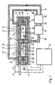
- the gas laser has a tubular body 1, preferably with a circular inner and outer cross section, in which both the laser gas 2, preferably CO 2 gas, and the laser beam are located.
- the mirror units 3 and 4 are attached to the two ends. The latter is equipped with the end mirror, while a partially transparent so-called decoupling mirror is located on the mirror unit 3.
- the generated laser beam exits via this and it arrives at a processing point or the like via a laser feed 5.
- the tubular body 1 is preferably formed into a U, as a result of which its length is reduced to approximately half. However, this requires the attachment of two deflecting mirrors 6 and 7 for the laser beam.
- the energy required to generate the laser beam is the tubular body supplied via two opposing electrodes, which is why it is a gas laser with cross coupling.
- the laser is operated with high-frequency energy, which comes from a high-frequency generator 8.
- the two electrodes which, as said, extend in the longitudinal direction of the tubular body and each encompass a partial circumference, are in partial electrodes 9, 10; 11, 12; 13, 14; 15, 16 divided.
- the sub-electrodes 9 and 10 or 11 and 12 or 13 and 14 or 15 and 16 each have the same length, the same size and the same shape and form a pair of sub-electrodes. All partial electrodes or pairs of partial electrodes are connected to a single common high-frequency generator 8 via lines shown in dash-dot lines.
- the tubular body has several gas inlets and outlets. Each sub-stream has an inlet and an outlet, but these can be summarized at least in part.
- both in the area of the mirror units 3 and 4 and the deflection mirror 6 and 7 each have an inlet 21, 22, 23, 24.
- the inlets 21 and 22 on the one hand and the inlets 23 and 24 on the other hand are preferably connected to one another in terms of flow via a channel 25 or 26 or the like.
- a feed line 27 or 28 leads to each, which is connected to one or two separate outlets of a blower 29, which draws in the cooled gas from a laser gas cooling device 31, if necessary, via a line 30.
- the heated laser gas flows to this cooling device, preferably via a common supply line 32.
- a common outlet 33 is provided for the partial flows 19 and 20.
- a discharge device 35 the two “double outlets” 33 and 34 are connected to one another via a symbolically drawn channel 36, which in turn is in flow connection with the common supply line 32. Conveniently, this ends, contrary to the schematic illustration, at the point marked by a circle 37. The same applies analogously to the channels 25 and 26.
- Corresponding to the discharge device 35 preferably identical feed devices 38 and 39 in the area of the channels 25 and 26.
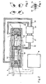
- the electrode pairs 40 to 43 are arranged offset from one another in the circumferential direction of the tubular body 1 in order to obtain a distribution of the energy in the gas stream that is as uniform as possible, as can be seen in FIG. 3.
- the tube sections on which the electrode pairs are located are rotatably mounted with respect to the other tube parts, the electrode pairs being firmly attached to the associated tube sections.
- Fig. 4 shows that a gear 44 is attached to a pipe section, in which a pinion 45 engages. This is connected to an adjusting device, not shown, which in turn can be connected to a program control or the like.
Landscapes
- Physics & Mathematics (AREA)
- Electromagnetism (AREA)
- Engineering & Computer Science (AREA)
- Plasma & Fusion (AREA)
- Optics & Photonics (AREA)
- Lasers (AREA)
Claims (6)
- Laser à gaz comprenant un corps tubulaire destiné à recevoir un gaz laser qui s'écoule le long du rayon laser, cependant que des électrodes destinées au couplage transversal d'énergie à haute fréquence se trouvent en face l'une de l'autre le long du corps tubulaire, que plusieurs entrées et sorties de gaz (21 à 24 ; 33, 34) se trouvent sur le corps tubulaire (1) pour diviser le courant de gaz laser en plusieurs courants partiels consécutifs (17, 18, 19, 20), que le corps tubulaire (1) est divisé par les entrées et les sorties en un nombre pair de sections d'écoulement et qu'au moins deux sections d'écoulement, mais de préférence quatre, sont présentes, et que les électrodes sont divisées en électrodes partielles (9 à 16) qui se trouvent les unes derrière les autres dans la direction longitudinale du corps tubulaire (1), chaque courant partiel (17 à 20) étant associé à une paire d'électrodes partielles (40, 41, 42, 43), et qu'en outre chaque courant partiel s'écoule à travers un dispositif de refroidissement (8) à chaque fois ou à travers un dispositif de refroidissement commun, caractérisé par le fait que les paires d'électrodes partielles (40, 41, 42, 43), ou des sections de celles-ci, sont disposées en étant décalées l'une par rapport à l'autre dans la direction de la périphérie du corps tubulaire (1), au moins une paire d'électrodes partielles (40 à 43) ou une section de celle-ci, respectivement, étant disposée en pouvant tourner par rapport au courant de gaz ou au rayon laser, respectivement.
- Laser selon la revendication 1, caractérisé par le fait que les paires d'électrodes partielles (40 à 43) ou leurs sections, respectivement, sont liées rigidement au corps tubulaire (1), et que celui-ci est divisé en plusieurs sections de tube dont l'une au moins est montée tournante.
- Laser selon la revendication 1 ou 2, caractérisé par le fait que les paires d'électrodes partielles montées tournantes (40 à 43) ou les sections de tube qui portent les paires d'électrodes partielles, respectivement, sont reliées à un dispositif de réglage (44, 45).
- Laser selon l'une des revendications 1 à 3, caractérisé par le fait qu'un dispositif de blocage est prévu pour les paires d'électrodes partielles tournantes ou les sections de tube tournantes qui les portent, respectivement.
- Laser selon l'une au moins des revendications précédentes, dans lequel une entrée de gaz (21, 22) est associée à chaque extrémité du corps tubulaire (1), caractérisé par le fait que le corps tubulaire (1) présente une forme en U, qu'une entrée (21, 22, 23, 24) se trouve à chaque fois, aussi bien dans la région des extrémités libres des ailes du U que de celles qui sont associées à la partie transversale du U, et qu'une sortie (33, 34) se trouve à chaque fois dans la région centrale des ailes du U.
- Laser selon la revendication 5, caractérisé par le fait que les entrées (21, 22) des extrémités libres des ailes du U et les entrées (23, 24) des extrémités des ailes du U qui sont associées à la partie transversale du U, ainsi que les deux sorties (33, 34), sont assemblées ou reliées entre elles à chaque fois en ce qui concerne l'écoulement.
Applications Claiming Priority (4)
| Application Number | Priority Date | Filing Date | Title |
|---|---|---|---|
| DE3442898 | 1984-11-24 | ||
| DE19843442898 DE3442898A1 (de) | 1984-11-24 | 1984-11-24 | Gas-laser mit quereinkopplung von hochfrequenzenergie |
| DE8526361U | 1985-09-14 | ||
| DE8526361U DE8526361U1 (de) | 1985-09-14 | 1985-09-14 | Gas-Laser |
Publications (3)
| Publication Number | Publication Date |
|---|---|
| EP0183023A2 EP0183023A2 (fr) | 1986-06-04 |
| EP0183023A3 EP0183023A3 (en) | 1987-09-23 |
| EP0183023B1 true EP0183023B1 (fr) | 1991-02-20 |
Family
ID=25826805
Family Applications (1)
| Application Number | Title | Priority Date | Filing Date |
|---|---|---|---|
| EP85112879A Expired - Lifetime EP0183023B1 (fr) | 1984-11-24 | 1985-10-11 | Laser à gaz avec accouplement transversal d'énergie à haute fréquence |
Country Status (2)
| Country | Link |
|---|---|
| US (1) | US4757511A (fr) |
| EP (1) | EP0183023B1 (fr) |
Families Citing this family (24)
| Publication number | Priority date | Publication date | Assignee | Title |
|---|---|---|---|---|
| JPS6327078A (ja) * | 1986-07-18 | 1988-02-04 | Fanuc Ltd | ガスレ−ザ装置 |
| DE3643735A1 (de) * | 1986-12-20 | 1988-07-07 | Tzn Forschung & Entwicklung | Gastransportlaser |
| DE3931082C2 (de) * | 1989-09-18 | 1996-05-30 | Tzn Forschung & Entwicklung | Gaslaser |
| JP2872855B2 (ja) * | 1992-02-19 | 1999-03-24 | ファナック株式会社 | レーザ発振器 |
| JP3022016B2 (ja) * | 1992-12-28 | 2000-03-15 | 松下電器産業株式会社 | 軸流形レーザ発振器 |
| US5351263A (en) * | 1993-07-01 | 1994-09-27 | Von Borstel Michael | Apparatus for a power laser including solid optical bench |
| US5867519A (en) * | 1996-08-07 | 1999-02-02 | Lumonics Inc. | Multiple element, folded beam laser |
| US5867518A (en) * | 1996-08-07 | 1999-02-02 | Lumonics Inc. | Multiple element laser pumping chamber |
| EP1066666B1 (fr) * | 1999-02-03 | 2008-08-06 | TRUMPF LASERTECHNIK GmbH | Laser muni d'un dispositif pour modifier la repartition de l'intensite de la lumiere laser sur la section transversale du faisceau laser |
| US6904075B1 (en) * | 1999-07-30 | 2005-06-07 | Mitsubishi Denki Kabushiki Kaisha | Orthogonal gas laser device |
| JP3619106B2 (ja) * | 2000-02-22 | 2005-02-09 | 三菱電機株式会社 | 自己補償形レーザ共振器 |
| US6928093B2 (en) * | 2002-05-07 | 2005-08-09 | Cymer, Inc. | Long delay and high TIS pulse stretcher |
| US20050259709A1 (en) | 2002-05-07 | 2005-11-24 | Cymer, Inc. | Systems and methods for implementing an interaction between a laser shaped as a line beam and a film deposited on a substrate |
| JP3787120B2 (ja) * | 2002-12-10 | 2006-06-21 | ファナック株式会社 | ガスレーザ発振装置 |
| US7277188B2 (en) * | 2003-04-29 | 2007-10-02 | Cymer, Inc. | Systems and methods for implementing an interaction between a laser shaped as a line beam and a film deposited on a substrate |
| US7577177B2 (en) * | 2004-01-12 | 2009-08-18 | Videojet Technologies Inc. | Multi-path laser system |
| US7583717B2 (en) * | 2004-08-30 | 2009-09-01 | Videojet Technologies Inc | Laser system |
| US7679029B2 (en) | 2005-10-28 | 2010-03-16 | Cymer, Inc. | Systems and methods to shape laser light as a line beam for interaction with a substrate having surface variations |
| US7317179B2 (en) | 2005-10-28 | 2008-01-08 | Cymer, Inc. | Systems and methods to shape laser light as a homogeneous line beam for interaction with a film deposited on a substrate |
| JP5499432B2 (ja) * | 2007-10-05 | 2014-05-21 | ソニー株式会社 | 撮像装置 |
| JP5429950B2 (ja) * | 2007-10-17 | 2014-02-26 | ギガフォトン株式会社 | レーザ装置 |
| US7733932B2 (en) * | 2008-03-28 | 2010-06-08 | Victor Faybishenko | Laser diode assemblies |
| US8432945B2 (en) | 2010-09-30 | 2013-04-30 | Victor Faybishenko | Laser diode combiner modules |
| US8855164B2 (en) | 2011-03-30 | 2014-10-07 | Gigaphoton Inc. | Laser apparatus |
Citations (3)
| Publication number | Priority date | Publication date | Assignee | Title |
|---|---|---|---|---|
| US4375690A (en) * | 1979-11-21 | 1983-03-01 | Mitsubishi Denki Kabushiki Kaisha | Multi-phase silent discharge gas laser apparatus |
| JPS603170A (ja) * | 1983-06-21 | 1985-01-09 | Mitsubishi Electric Corp | 無声放電式ガスレ−ザ装置 |
| EP0152084A2 (fr) * | 1984-02-13 | 1985-08-21 | Mitsubishi Denki Kabushiki Kaisha | Dispositif laser à gaz |
Family Cites Families (46)
| Publication number | Priority date | Publication date | Assignee | Title |
|---|---|---|---|---|
| US31279A (en) * | 1861-01-29 | William burnett | ||
| NL6411121A (fr) * | 1964-09-24 | 1966-03-25 | ||
| US3524144A (en) * | 1965-07-13 | 1970-08-11 | Us Army | Laser generator having a shock-induced narrow band illuminator |
| US3577096A (en) * | 1967-11-01 | 1971-05-04 | Hughes Aircraft Co | Transverse discharge gas laser |
| US3683297A (en) * | 1968-11-22 | 1972-08-08 | Coherent Radiation Lab | Optical cavity for a laser |
| CA897238A (en) * | 1969-08-29 | 1972-04-04 | Her Majesty The Queen In Right Of Canada As Represented By The Minister Of National Defence Of Her Majesty's Canadian Government | Energization of molecular gas laser for mode and scatter control |
| US3743963A (en) * | 1969-09-10 | 1973-07-03 | United Aircraft Corp | Transverse gas laser |
| US3660778A (en) * | 1970-06-16 | 1972-05-02 | Leo J Le Blanc Sr | Laser beam folding device |
| DE2132492C3 (de) * | 1971-06-30 | 1974-10-17 | Kernforschungsanlage Juelich Gmbh, 5170 Juelich | Verfahren zur Herstellung von als Ausgangsmaterial zur Herstellung von Kunstgraphiten oder graphitähnlichen Werkstoffen dienendem Mischpulver |
| US3704428A (en) * | 1971-10-04 | 1972-11-28 | Us Air Force | Carbon monoxide laser from helium-air-methane mixture |
| FR2185874B1 (fr) * | 1972-05-24 | 1974-12-27 | Thomson Csf | |
| US3748594A (en) * | 1972-06-22 | 1973-07-24 | Avco Corp | Radio frequency electrically excited flowing gas laser |
| US3787781A (en) * | 1972-08-07 | 1974-01-22 | Us Air Force | External cathode/internal anode figure eight laser |
| USRE31279E (en) | 1972-09-26 | 1983-06-14 | Laser optical resonator | |
| US3783407A (en) * | 1972-09-26 | 1974-01-01 | Coherent Radiation Labor | Improved laser optical resonator |
| US4064465A (en) * | 1973-05-30 | 1977-12-20 | Westinghouse Electric Corporation | Laser cavities with gas flow through the electrodes |
| US3935547A (en) * | 1973-05-30 | 1976-01-27 | Westinghouse Electric Corporation | High pressure gas laser using uniform field electrode configuration with irradiation by corona discharge |
| US3855547A (en) * | 1973-11-29 | 1974-12-17 | Ibm | Optical cavity for a laser |
| US3900804A (en) * | 1973-12-26 | 1975-08-19 | United Aircraft Corp | Multitube coaxial closed cycle gas laser system |
| US3919663A (en) * | 1974-05-23 | 1975-11-11 | United Technologies Corp | Method and apparatus for aligning laser reflective surfaces |
| US3921097A (en) * | 1974-05-30 | 1975-11-18 | Avco Everett Res Lab Inc | Crossed-field excitation, pulsed gas laser |
| FR2306550A1 (fr) * | 1975-04-03 | 1976-10-29 | Cilas | Generateur laser |
| NL7708349A (nl) * | 1977-07-28 | 1979-01-30 | Philips Nv | Gasontladingslaserinrichting. |
| US4180784A (en) * | 1977-09-19 | 1979-12-25 | The Boeing Company | Frequency modulated electrical discharge laser |
| US4169251A (en) * | 1978-01-16 | 1979-09-25 | Hughes Aircraft Company | Waveguide gas laser with high frequency transverse discharge excitation |
| JPS5811110B2 (ja) * | 1978-06-28 | 1983-03-01 | 株式会社日立製作所 | ガスレ−ザ発生装置 |
| JPS5839396B2 (ja) * | 1978-08-25 | 1983-08-30 | 株式会社日立製作所 | ガスレ−ザ発生装置 |
| US4242647A (en) * | 1978-10-27 | 1980-12-30 | Macken John A | Stabilized vortex convective laser |
| JPS55113391A (en) * | 1979-02-21 | 1980-09-01 | Hitachi Ltd | Gas flow type laser device |
| US4237430A (en) * | 1979-02-27 | 1980-12-02 | Westinghouse Electric Corp. | Coaxial discharge sealed-off quartz laser tube |
| JPS5619691A (en) * | 1979-07-27 | 1981-02-24 | Hitachi Ltd | Gas sealed type laser oscillator |
| US4423510A (en) * | 1979-08-17 | 1983-12-27 | Westinghouse Electric Corp. | Laser tube design incorporating low inductance capacitor |
| US4287483A (en) * | 1979-09-04 | 1981-09-01 | Raytheon Company | Transverse excitation laser |
| US4499582A (en) * | 1980-04-05 | 1985-02-12 | Heinrich Karning | Laser system |
| US4359777A (en) * | 1981-01-22 | 1982-11-16 | The United States Of America As Represented By The Secretary Of The Army | High efficiency transversely excited electrodeless gas lasers |
| IT1171313B (it) * | 1981-06-17 | 1987-06-10 | Selenia Ind Elettroniche | Laser a scarica longitudinale ad impulsi con preionizzazione ottenuta mediante effetto corona |
| JPS5843588A (ja) * | 1981-09-09 | 1983-03-14 | Hitachi Ltd | レ−ザ発生装置 |
| US4426705A (en) * | 1981-10-06 | 1984-01-17 | The United States Of America As Represented By The Secretary Of The Air Force | Double electric discharge coaxial laser |
| GB2108752B (en) * | 1981-11-02 | 1986-04-09 | Raytheon Co | Laser system |
| US4464760A (en) * | 1982-04-20 | 1984-08-07 | Sutter Jr Leroy V | Elongated chambers for use in combination with a transversely excited gas laser |
| US4455658A (en) * | 1982-04-20 | 1984-06-19 | Sutter Jr Leroy V | Coupling circuit for use with a transversely excited gas laser |
| JPS5986278A (ja) * | 1982-11-10 | 1984-05-18 | Hitachi Ltd | 高速軸流形ガスレ−ザ装置 |
| JPS59136983A (ja) * | 1983-01-26 | 1984-08-06 | Hitachi Ltd | ガスレ−ザ発生装置 |
| JPS6054488A (ja) * | 1983-09-05 | 1985-03-28 | Matsushita Electric Ind Co Ltd | レ−ザ発振器 |
| JPS6057986A (ja) * | 1983-09-09 | 1985-04-03 | Hitachi Ltd | ガスレ−ザ発生装置 |
| US4596018A (en) * | 1983-10-07 | 1986-06-17 | Minnesota Laser Corp. | External electrode transverse high frequency gas discharge laser |
-
1985
- 1985-10-11 EP EP85112879A patent/EP0183023B1/fr not_active Expired - Lifetime
- 1985-11-22 US US06/800,975 patent/US4757511A/en not_active Expired - Lifetime
Patent Citations (3)
| Publication number | Priority date | Publication date | Assignee | Title |
|---|---|---|---|---|
| US4375690A (en) * | 1979-11-21 | 1983-03-01 | Mitsubishi Denki Kabushiki Kaisha | Multi-phase silent discharge gas laser apparatus |
| JPS603170A (ja) * | 1983-06-21 | 1985-01-09 | Mitsubishi Electric Corp | 無声放電式ガスレ−ザ装置 |
| EP0152084A2 (fr) * | 1984-02-13 | 1985-08-21 | Mitsubishi Denki Kabushiki Kaisha | Dispositif laser à gaz |
Non-Patent Citations (1)
| Title |
|---|
| PATENT ABSTRACTS OF JAPAN vol. 009, no. 110 (E - 314)<1833> 15 May 1985 (1985-05-15) * |
Also Published As
| Publication number | Publication date |
|---|---|
| US4757511A (en) | 1988-07-12 |
| EP0183023A3 (en) | 1987-09-23 |
| EP0183023A2 (fr) | 1986-06-04 |
Similar Documents
| Publication | Publication Date | Title |
|---|---|---|
| EP0183023B1 (fr) | Laser à gaz avec accouplement transversal d'énergie à haute fréquence | |
| EP0621920B1 (fr) | Refroidissement de la bande de protection d'une aube de turbine | |
| DE2840103C2 (fr) | ||
| DE102013003939B4 (de) | Laserstrahl-Umlenkeinrichtung für eine Vorrichtung zum Bauen dreidimensionaler Objekte und Vorrichtung zur Erzeugung dreidimensionaler Objekte mit einer solchen Laserstrahl-Umlenkeinrichtung | |
| DE2839552C3 (de) | Düsenkopf zum Herstellen von Kunststoffgranulat | |
| DE3312422A1 (de) | Vorrichtung zur erzeugung von flockigen teilchen | |
| DE4428370C1 (de) | Anordnung mit einer Vielzahl von entlang einer Längsachse gestreckten und entlang einer Hochachse aufeinander gestapelten Leiterstäben | |
| DE3427639A1 (de) | Verfahren und vorrichtung zum biegen laenglicher werkstuecke, insbesondere rohre | |
| DE2500079C2 (de) | Vorrichtung zum Kühlen in einer Stranggießanlage | |
| EP0931600B1 (fr) | Dispositif pour le décalaminage de produits laminés | |
| DE3339076A1 (de) | Gekuehlter spiegel, insbesondere fuer laser | |
| DE1297938B (de) | Leitschaufel mit Waermeschild, insbesondere fuer Gasturbinen | |
| DE1007178C2 (de) | Regelbares Strahltriebwerk fuer Flugzeuge u. dgl. mit Strahlumlenkung | |
| DE3523829C2 (fr) | ||
| DE10354422B4 (de) | Spritzgießdüse für eine Spritzgießvorrichtung | |
| EP0215458B1 (fr) | Laser à gaz | |
| DE3442898A1 (de) | Gas-laser mit quereinkopplung von hochfrequenzenergie | |
| DE1690547B2 (de) | Vorrichtung zum einstellen der wirksamen laenge eines induk tors zum erwaermen metallischer werkstuecke | |
| LU85568A1 (de) | Verstellbare stranggiesskokillenanordnung | |
| DE1816075A1 (de) | Gaslaser mit Kuehlmantel | |
| EP0380827B1 (fr) | Installation de compacter pour pulvériser horizontalement | |
| DE1604607B2 (de) | Vorrichtung zum verschweissen der lagen von thermoplastischen kunststofffolien | |
| DE2405884B2 (de) | Anordnung zur kuehlung der auf einem umlaufenden kollektor schleifenden, ortsfesten, voneinander beabstandeten kontaktbuersten einer elektrischen maschine mittels eines kuehlluftstromes | |
| DE3333911A1 (de) | Vorrichtung zum biegen von rohren oder dgl. | |
| DE69400303T2 (de) | Halterungsanordnung für Widerstandsbänder für Leistungswiderstände |
Legal Events
| Date | Code | Title | Description |
|---|---|---|---|
| PUAI | Public reference made under article 153(3) epc to a published international application that has entered the european phase |
Free format text: ORIGINAL CODE: 0009012 |
|
| AK | Designated contracting states |
Kind code of ref document: A2 Designated state(s): CH FR GB IT LI |
|
| PUAL | Search report despatched |
Free format text: ORIGINAL CODE: 0009013 |
|
| AK | Designated contracting states |
Kind code of ref document: A3 Designated state(s): CH FR GB IT LI |
|
| 17P | Request for examination filed |
Effective date: 19871230 |
|
| 17Q | First examination report despatched |
Effective date: 19891120 |
|
| GRAA | (expected) grant |
Free format text: ORIGINAL CODE: 0009210 |
|
| AK | Designated contracting states |
Kind code of ref document: B1 Designated state(s): CH FR GB IT LI |
|
| GBT | Gb: translation of ep patent filed (gb section 77(6)(a)/1977) | ||
| ITF | It: translation for a ep patent filed | ||
| ET | Fr: translation filed | ||
| PLBE | No opposition filed within time limit |
Free format text: ORIGINAL CODE: 0009261 |
|
| STAA | Information on the status of an ep patent application or granted ep patent |
Free format text: STATUS: NO OPPOSITION FILED WITHIN TIME LIMIT |
|
| 26N | No opposition filed | ||
| REG | Reference to a national code |
Ref country code: GB Ref legal event code: IF02 |
|
| PGFP | Annual fee paid to national office [announced via postgrant information from national office to epo] |
Ref country code: GB Payment date: 20031020 Year of fee payment: 19 |
|
| PGFP | Annual fee paid to national office [announced via postgrant information from national office to epo] |
Ref country code: FR Payment date: 20031021 Year of fee payment: 19 |
|
| PGFP | Annual fee paid to national office [announced via postgrant information from national office to epo] |
Ref country code: CH Payment date: 20031023 Year of fee payment: 19 |
|
| PG25 | Lapsed in a contracting state [announced via postgrant information from national office to epo] |
Ref country code: GB Free format text: LAPSE BECAUSE OF NON-PAYMENT OF DUE FEES Effective date: 20041011 |
|
| PG25 | Lapsed in a contracting state [announced via postgrant information from national office to epo] |
Ref country code: CH Free format text: LAPSE BECAUSE OF NON-PAYMENT OF DUE FEES Effective date: 20041031 Ref country code: LI Free format text: LAPSE BECAUSE OF NON-PAYMENT OF DUE FEES Effective date: 20041031 |
|
| GBPC | Gb: european patent ceased through non-payment of renewal fee |
Effective date: 20041011 |
|
| REG | Reference to a national code |
Ref country code: CH Ref legal event code: PL |
|
| PG25 | Lapsed in a contracting state [announced via postgrant information from national office to epo] |
Ref country code: FR Free format text: LAPSE BECAUSE OF NON-PAYMENT OF DUE FEES Effective date: 20050630 |
|
| REG | Reference to a national code |
Ref country code: FR Ref legal event code: ST |