EP0183256B1 - Methode de fabrication d'un element membrane semi-permeable de fibre creuse et un element membrane semi-permeable de fibre creuse - Google Patents
Methode de fabrication d'un element membrane semi-permeable de fibre creuse et un element membrane semi-permeable de fibre creuse Download PDFInfo
- Publication number
- EP0183256B1 EP0183256B1 EP85115087A EP85115087A EP0183256B1 EP 0183256 B1 EP0183256 B1 EP 0183256B1 EP 85115087 A EP85115087 A EP 85115087A EP 85115087 A EP85115087 A EP 85115087A EP 0183256 B1 EP0183256 B1 EP 0183256B1
- Authority
- EP
- European Patent Office
- Prior art keywords
- hollow fiber
- end portions
- rubber
- fiber semipermeable
- membranes
- Prior art date
- Legal status (The legal status is an assumption and is not a legal conclusion. Google has not performed a legal analysis and makes no representation as to the accuracy of the status listed.)
- Expired - Lifetime
Links
Images


Classifications
-
- B—PERFORMING OPERATIONS; TRANSPORTING
- B01—PHYSICAL OR CHEMICAL PROCESSES OR APPARATUS IN GENERAL
- B01D—SEPARATION
- B01D63/00—Apparatus in general for separation processes using semi-permeable membranes
- B01D63/02—Hollow fibre modules
- B01D63/021—Manufacturing thereof
- B01D63/022—Encapsulating hollow fibres
- B01D63/0223—Encapsulating hollow fibres by fixing the hollow fibres prior to encapsulation
-
- B—PERFORMING OPERATIONS; TRANSPORTING
- B01—PHYSICAL OR CHEMICAL PROCESSES OR APPARATUS IN GENERAL
- B01D—SEPARATION
- B01D63/00—Apparatus in general for separation processes using semi-permeable membranes
- B01D63/02—Hollow fibre modules
- B01D63/021—Manufacturing thereof
- B01D63/022—Encapsulating hollow fibres
- B01D63/023—Encapsulating materials
-
- B—PERFORMING OPERATIONS; TRANSPORTING
- B29—WORKING OF PLASTICS; WORKING OF SUBSTANCES IN A PLASTIC STATE IN GENERAL
- B29C—SHAPING OR JOINING OF PLASTICS; SHAPING OF MATERIAL IN A PLASTIC STATE, NOT OTHERWISE PROVIDED FOR; AFTER-TREATMENT OF THE SHAPED PRODUCTS, e.g. REPAIRING
- B29C70/00—Shaping composites, i.e. plastics material comprising reinforcements, fillers or preformed parts, e.g. inserts
- B29C70/68—Shaping composites, i.e. plastics material comprising reinforcements, fillers or preformed parts, e.g. inserts by incorporating or moulding on preformed parts, e.g. inserts or layers, e.g. foam blocks
- B29C70/84—Shaping composites, i.e. plastics material comprising reinforcements, fillers or preformed parts, e.g. inserts by incorporating or moulding on preformed parts, e.g. inserts or layers, e.g. foam blocks by moulding material on preformed parts to be joined
- B29C70/845—Shaping composites, i.e. plastics material comprising reinforcements, fillers or preformed parts, e.g. inserts by incorporating or moulding on preformed parts, e.g. inserts or layers, e.g. foam blocks by moulding material on preformed parts to be joined by moulding material on a relative small portion of the preformed parts
-
- Y—GENERAL TAGGING OF NEW TECHNOLOGICAL DEVELOPMENTS; GENERAL TAGGING OF CROSS-SECTIONAL TECHNOLOGIES SPANNING OVER SEVERAL SECTIONS OF THE IPC; TECHNICAL SUBJECTS COVERED BY FORMER USPC CROSS-REFERENCE ART COLLECTIONS [XRACs] AND DIGESTS
- Y10—TECHNICAL SUBJECTS COVERED BY FORMER USPC
- Y10T—TECHNICAL SUBJECTS COVERED BY FORMER US CLASSIFICATION
- Y10T428/00—Stock material or miscellaneous articles
- Y10T428/29—Coated or structually defined flake, particle, cell, strand, strand portion, rod, filament, macroscopic fiber or mass thereof
- Y10T428/2913—Rod, strand, filament or fiber
- Y10T428/2929—Bicomponent, conjugate, composite or collateral fibers or filaments [i.e., coextruded sheath-core or side-by-side type]
-
- Y—GENERAL TAGGING OF NEW TECHNOLOGICAL DEVELOPMENTS; GENERAL TAGGING OF CROSS-SECTIONAL TECHNOLOGIES SPANNING OVER SEVERAL SECTIONS OF THE IPC; TECHNICAL SUBJECTS COVERED BY FORMER USPC CROSS-REFERENCE ART COLLECTIONS [XRACs] AND DIGESTS
- Y10—TECHNICAL SUBJECTS COVERED BY FORMER USPC
- Y10T—TECHNICAL SUBJECTS COVERED BY FORMER US CLASSIFICATION
- Y10T428/00—Stock material or miscellaneous articles
- Y10T428/29—Coated or structually defined flake, particle, cell, strand, strand portion, rod, filament, macroscopic fiber or mass thereof
- Y10T428/2913—Rod, strand, filament or fiber
- Y10T428/2933—Coated or with bond, impregnation or core
-
- Y—GENERAL TAGGING OF NEW TECHNOLOGICAL DEVELOPMENTS; GENERAL TAGGING OF CROSS-SECTIONAL TECHNOLOGIES SPANNING OVER SEVERAL SECTIONS OF THE IPC; TECHNICAL SUBJECTS COVERED BY FORMER USPC CROSS-REFERENCE ART COLLECTIONS [XRACs] AND DIGESTS
- Y10—TECHNICAL SUBJECTS COVERED BY FORMER USPC
- Y10T—TECHNICAL SUBJECTS COVERED BY FORMER US CLASSIFICATION
- Y10T428/00—Stock material or miscellaneous articles
- Y10T428/29—Coated or structually defined flake, particle, cell, strand, strand portion, rod, filament, macroscopic fiber or mass thereof
- Y10T428/2913—Rod, strand, filament or fiber
- Y10T428/2933—Coated or with bond, impregnation or core
- Y10T428/2935—Discontinuous or tubular or cellular core
-
- Y—GENERAL TAGGING OF NEW TECHNOLOGICAL DEVELOPMENTS; GENERAL TAGGING OF CROSS-SECTIONAL TECHNOLOGIES SPANNING OVER SEVERAL SECTIONS OF THE IPC; TECHNICAL SUBJECTS COVERED BY FORMER USPC CROSS-REFERENCE ART COLLECTIONS [XRACs] AND DIGESTS
- Y10—TECHNICAL SUBJECTS COVERED BY FORMER USPC
- Y10T—TECHNICAL SUBJECTS COVERED BY FORMER US CLASSIFICATION
- Y10T428/00—Stock material or miscellaneous articles
- Y10T428/29—Coated or structually defined flake, particle, cell, strand, strand portion, rod, filament, macroscopic fiber or mass thereof
- Y10T428/2913—Rod, strand, filament or fiber
- Y10T428/2933—Coated or with bond, impregnation or core
- Y10T428/294—Coated or with bond, impregnation or core including metal or compound thereof [excluding glass, ceramic and asbestos]
- Y10T428/296—Rubber, cellulosic or silicic material in coating
-
- Y—GENERAL TAGGING OF NEW TECHNOLOGICAL DEVELOPMENTS; GENERAL TAGGING OF CROSS-SECTIONAL TECHNOLOGIES SPANNING OVER SEVERAL SECTIONS OF THE IPC; TECHNICAL SUBJECTS COVERED BY FORMER USPC CROSS-REFERENCE ART COLLECTIONS [XRACs] AND DIGESTS
- Y10—TECHNICAL SUBJECTS COVERED BY FORMER USPC
- Y10T—TECHNICAL SUBJECTS COVERED BY FORMER US CLASSIFICATION
- Y10T428/00—Stock material or miscellaneous articles
- Y10T428/29—Coated or structually defined flake, particle, cell, strand, strand portion, rod, filament, macroscopic fiber or mass thereof
- Y10T428/2913—Rod, strand, filament or fiber
- Y10T428/2933—Coated or with bond, impregnation or core
- Y10T428/2964—Artificial fiber or filament
- Y10T428/2967—Synthetic resin or polymer
-
- Y—GENERAL TAGGING OF NEW TECHNOLOGICAL DEVELOPMENTS; GENERAL TAGGING OF CROSS-SECTIONAL TECHNOLOGIES SPANNING OVER SEVERAL SECTIONS OF THE IPC; TECHNICAL SUBJECTS COVERED BY FORMER USPC CROSS-REFERENCE ART COLLECTIONS [XRACs] AND DIGESTS
- Y10—TECHNICAL SUBJECTS COVERED BY FORMER USPC
- Y10T—TECHNICAL SUBJECTS COVERED BY FORMER US CLASSIFICATION
- Y10T428/00—Stock material or miscellaneous articles
- Y10T428/29—Coated or structually defined flake, particle, cell, strand, strand portion, rod, filament, macroscopic fiber or mass thereof
- Y10T428/2913—Rod, strand, filament or fiber
- Y10T428/2973—Particular cross section
- Y10T428/2975—Tubular or cellular
Definitions
- This invention relates to a method of producing a hollow fiber semipermeable membrane element and to the hollow fiber semipermeable membrane element obtained by this method. More particularly, the present invention is concerned with a method for producing a hollow fiber semipermeable membrane element, said hollow fiber semipermeable membranes having their respective one end portions or both end portions bonded together by means of a vulcanized fluoro rubber, so that the semipermeable membrane element has a high resistance to chemicals. The present invention is also concerned with such a hollow fiber semipermeable membrane element.
- Modules in which hollow fiber semipermeable membranes are incorporated are widely used because they are large in effective membrane area and, therefore, economically advantageous, as compared with modules of the plate, spiral and tubular types.
- the conventional modules of the hollow fiber semipermeable membrane type have drawbacks.
- in assembling the hollow fiber semipermeable membranes into a module it is necessary to seal, by means of an adhesive, spacings between the semipermeable membranes as well as between the semipermeable membranes and the inner wall of a housing, at their respective one end portions or both end portions.
- the adhesive there are usually used those of an epoxy type.
- the modules in which the sealing is made by means of an epoxy type adhesive cannot be suitably employed not only for the filtration of strong acids such as concentrated sulfuric acid, nitric acid, glacial acetic acid, etc. used for washing of semiconductors or etching procedures, but also for the filtration of organic solvents such as methanol, trichloroethylene, isopropyl alcohol, acetone, methyl ethyl ketone, ethyl acetate, etc.
- polymeric elastomers such as natural and synthetic rubber, urethanes, polysulfides and silicones having sufficiently low viscosity as sealants (DE-A-22 39 931 corresponding to U.S. Patent No. 3 760 949).
- the chemical resistance of these materials is also insufficient.
- fluoro resins and fluoro rubbers are known to have a resistance to chemicals.
- fluorocarbon elastomers having resistance to oil, fats, O3, solvents, acids, bases, phosphate ester hydraulic fluids, synthetic lubricants and fuels and having a low compression set as conventional sealing materials ("Fluorocarbon elastomers as sealing materials for high requirements" KAUTSCH. GUMMI, KUNSTST. 1976, 29 (12), 761 - 766).
- a method of producing a hollow fiber semipermeable membrane element which comprises the steps of (1) coating the peripheral surfaces of a vast plurality of hollow fiber semipermeable membranes at their respective one end portions or both end portions with a solution of an unvulcanized fluoro rubber containing a vulcanizing agent to form an unvulcanized fluoro rubber coat at the end portions, (2) arranging said semipermeable membranes into a bundle, and (3) subjecting said bundle to vulcanization of the unvulcanized fluoro rubber coat while pressing the hollow fiber semipermeable membranes at their coated end portions, thereby bonding the end portions of said semipermeable membranes together by means of the vulcanized fluoro rubber.
- a hollow fiber semipermeable membrane element comprising a vast plurality of hollow fiber semipermeable membranes substantially equal in length, arranged in a lengthwise direction and bonded together by means of a vulcanized rubber at their respective one end portions or both end portions, wherein the vulcanized rubber is a vulcanized fluororubber.
- FIG. 1 there is shown one form of a hollow fiber semipermeable membrane element of the present invention.
- Figs. 2 to 3 illustrate how to prepare a bundle of hollow fiber semipermeable membranes having their end portions coated and bonded together by means of an unvulcanized fluoro rubber, which bundle is to be used for forming a hollow fiber semipermeable membrane element of the present invention.
- predetermined lengths of hollow fiber semipermeable membranes are attached to a frame 2 made of stainless steel through a double-coated adhesive tape.
- the upper side of the frame 2 having the membranes 1 attached thereto is dipped in a solution containing an unvulcanized fluoro rubber, followed by drying.
- This operation is repeated several times to form a unvulcanized fluoro rubber coat at one end portions of the membranes 1.
- the lower side of the frame 2 is also treated in the same manner as mentioned above to form a unvulcanized fluoro rubber coat at the other end portions of the membranes 1.
- the membranes 1 are cut at their respective portions inside the upper and lower sides of the frame 2 to obtain a vast plurality of hollow fiber semipermeable membranes 1 having their both end portions coated with an unvulcanized fluoro rubber (not shown).
- the thus obtained membranes 1 are bundled, with their both ends arranged uniformly, into a cylindrical form.
- an unvulcanized fluoro rubber sheet 4 Around the cylindrical membrane bundle 3 at its both end portions coated with the unvulcanized fluoro rubber is wound an unvulcanized fluoro rubber sheet 4, to form a cylindrical membrane bundle assembly as depicted in Fig. 3.
- the thus obtained cylindrical membrane bundle assembly is fittedly inserted in a perforated pipe 5 having a length a little smaller than that of the cylindrical membrane bundle assembly so that the both end portions of the cylindrical membrane bundle assembly protrude out of the both ends of the pipe 5.
- the hollow fiber semipermeable membrane there may be employed any of those which are conventionally known and have various pore sizes and various fiber diameters and are made of various materials. But, from a view point of resistance to chemicals, those membranes made of fluoro resins, silicone resins, polyolefin resins, polyimide resins, polyacrylonitrile resins, polyamide resins, and the like are preferred.
- the unvulcanized fluoro rubber there may be employed any of those which are soluble in a solvent and will give an excellent property rubber after vulcanization.
- Example of the suitable unvulcanized fluoro rubbers include such as a vinylidene fluoride-hexafluoropropylene copolymer, a vinylidene fluoride-hexafluoropropylene-tetrafluoroethylene terpolymer, and a tetrafluoroetylene-propylene copolymer;
- a vulcanizing agent there may be employed any of those which are capable of vulcanizing the unvulcanized rubbers, and may generally be used organic peroxides, polyols, and amines. Suitable vulcanizing agents are chosen depending on the kind of the unvulcanized fluoro rubber used. The vulcanizing agent may be employed in an amount of 1 to 10 parts by weight per 100 parts by weight of the unvulcanized fluoro rubber.
- suitable additives such as a reinforcing agent, vulcanizing accelerator, plasticizer and processing aid may be incorporated in an unvulcanized rubber.
- the reinforcing agent for increasing the mechanical strength of the sealing rubber including the hardness of rubber
- the reinforcing agent may be employed in an amount of 1 to 100 parts by weight per 100 parts by weight of the unvulcanized rubber, namely, after vulcanization, 1 to 100 % by weight based on the weight of the rubber value of the vulcanized fluoro rubber. If the amount of the reinforcing agent is less than 1 % by weight, the intended effect cannot be exerted.
- the amount of the reinforcing agent is more than 100 % by weight, the flowability of the rubber is decreased, so that in vulcanizing the unvulcanized fluoro rubber while pressing it, gaps tend to be formed between the rubber and the hollow fiber semipermeable membranes, leading to insufficient sealing.
- a graphite fluoride is most preferred.
- a graphite fluoride is obtained by direct fluorination of a carbon material, but the composition of a graphite fluoride formed by the fluorination of a carbon material is widely varied depending on the reaction temperature and the kind or crystallinity of the raw carbon material.
- (CF) n may be produced by reacting an amorphous carbon material, such as petroleum coke, with fluorine at a temperature of about 200 °C to about 450 °C, and (CF) n or (CF) n -rich mixtures of (CF) n and (C2F) n may be produced by reacting a crystalline carbon material, such as natural and artificial graphites, with fluorine at a temperature of about 500 °C to about 630 °C.
- Compounds of (CF) n are produced with varied crystallinities, and those having high crystallinities are white solids.
- (C2F) n or (C2F) n -rich mixtures of (C2F) n and (CF) n may be produced by reacting a crystalline carbon material, such as natural and artificial graphites, with fluorine at a temperature of about 300 °C to about 500 °C.
- the color of (C2F) n is black under the conditions for the formation thereof and changes from black through grey to white by heat treatment thereof at an elevated temperature up to about 600 °C with increase of crystallinity.
- the resulting graphite fluoride product is (CF) n -rich in the event that the fluorination is conducted at a temperature higher than about 500 °C, whereas it is (C2F) n -rich in the event that the fluorination is conducted at a temperature up to about 500 °C.
- the boundary temperature is not about 500 °C but 470 °C.
- a graphite fluoride having any F/C ratio may be employed, however, from a viewpoint of the increased effect, a graphite fluoride with a F/C ratio of substantially 1:1 is preferred. It is preferred to use a graphite fluoride having a particle size of 0.1 to 2 ⁇ m.
- One end portions or both end portions of hollow fiber semipermeable membranes are dipped in a solution of unvulcanized fluoro rubber containing a vulcanizing agent to coat the peripheral walls of the end portions of the membranes.
- the length of the end portions to be coated is preferably 10 mm or more. If such a length is smaller than 10 mm, the open ends of the membranes of the resulting membrane element are caused to collapse even under the low pressure which is applied to the element in actual use, so that the filtration pressure to be applied is restricted. On the other hand, the larger the length of the end portions to be coated, the more the pressure resistance of the element, but the less the effective membrane area. For this reason, the length of the end portions to be coated should be appropriately determined depending on the diameter of the element and the filtration pressure to be used.
- the solvent for making a solution of unvulcanized fluoro rubber containing a vulcanizing agent there may be employed any of those which are good solvents for the unvulcanized fluoro rubber containing the vulcanizing agent and non-solvents for the hollow fiber semipermeable membranes.
- the concentration of the solution may preferably be 10 to 50 % by weight. If the concentration is less than 10 % by weight, the number of times of repetition of dipping and drying for obtaining the desired thickness of a coating is increased and, in addition, a long period of time is required. On the other hand, if the concentration is more than 50 % by weight, the thickness of a coating becomes too large, causing the number of hollow fiber semipermeable membranes in the membrane element to be reduced, which leads to a decrease in effective membrane area.
- coated membranes are dried at a temperature lower than the vulcanizing point of the unvulcanized fluoro rubber to obtain a dried coating of a thickness of 0.05 to 10 mm, preferably 0.1 to 5 mm. If the thickness of the coating is less than 0.05 mm, the sealing between the hollow fiber semipermeable membranes will be insufficient after vulcanization is effected while pressing a bundle of the coated semipermeable membranes in a mold.
- the thickness of the coating is more than 10 mm, when vulcanization is effected while pressing a bundle of the coated semipermeable membranes in a mold, the vulcanized fluoro rubber tends to be forced out of the bundle and the effective membrane area per unit module is caused to be disadvantageously decreased.
- a vast plurality of the thus obtained hollow fiber semipermeable membranes having their end portions coated with the unvulcanized fluoro rubber are bundled, with their both ends arranged properly, into a cylindrical form.
- an unvulcanized rubber film or sheet Around the cylindrical membrane bundle at its end portion coated with the unvulcanized fluoro rubber is wound an unvulcanized rubber film or sheet to form a cylindrical membrane bundle assembly.
- the thus obtained cylindrical membrane bundle assembly is subjected to vulcanization of the unvulcanized fluoro rubber in an oven while being pressed, to an extent that the diameter of the bundle is reduced by about 10 %, in a heated split mold.
- the oven is operated with an appropriate atmosphere for the kind of the rubber used, such as in vacuum, or with a nitrogen or steam atmosphere.
- predetermined lengths of hollow fiber semipermeable membranes are attached, one by one, to a frame 2 made of stainless steel through a double-coated adhesive tape.
- An upper side of the frame 2 having the membranes 1 attached thereto is dipped in a solution containing an unvulcanized fluoro rubber, followed by drying. This operation is repeated several times to form an unvulcanized fluoro rubber coat at one end portions of the membranes 1.
- the lower side of the frame 2 is also treated in the same manner as mentioned above to form an unvulcanized fluoro rubber coat at the other end portions of the membranes 1.
- the membranes 1 are cut at their respective portions inside the upper and lower sides of the frame 2 to obtain a vast plurality of hollow fiber semipermeable membranes 1 having their both end portions coated with an unvulcanized fluoro rubber (not shown).
- the thus obtained membranes 1 are bundled, with their both ends arranged uniformly, into a cylindrical form.
- the procedure as mentioned above is somewhat troublesome.
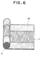
- a hollow fiber semipermeable membrane 1 is wound around a frame 2 over its upper and lower sides so that the hollow fiber semipermeable membranes 1 are densely arranged substantially in parallel at predetermined intervals.
- the frame 2 with the membrane wound therearound is dipped from its upper side in a solution of an unvulcanized fluoro rubber containing a vulcanizing agent to a necessary depth, thereby to coat one end portions of the semipermeable membranes with the unvulcanized fluoro rubber, followed by drying at a temperature lower than the vulcanizing point of the rubber used.
- the same treatment is effected to coat the other end portions of the semipermeable membranes with dried unvulcanized fluoro rubber.
- the membranes 1 are cut at their respective portions inside the upper and lower sides of the frame 2 to obtain a sheet-like form of a vast plurality of hollow fiber semipermeable membranes bonded together at their both end portions by means of the dried unvulcanized coating fluoro rubber 11.
- a cylindrical membrane bundle composed of semipermeable membranes of which the both end portions are properly arranged can be obtained in a shortened period of time with advantages.
- the thus obtained cylindrical membrane bundle composed of semipermeable membranes with their end portions coated with the unvulcanized fluoro rubber is subjected to vulcanization of the unvulcanized rubber as described above, thereby to obtain a hollow fiber semipermeable membrane element of the present invention.
- the semipermeable membrane element is accommodated in a housing made of polytetrafluoroetylene, which has a resistance to chemicals, (hereinafter often referred to as "PTFE") or the like and sealed by means of an O-ring made of a fluoro resin or the like which is also resistant to chemicals, thus providing a semipermeable module which is excellent in resistance to chemicals.
- PTFE polytetrafluoroetylene
- the bonding portions are made of rubber and, therefore, there is a danger that the bonding portions are deformed when a high pressure is applied.
- a suitable reinforcement such as a pipe or rod made of a fluoro resin which is resistant to chemicals may preferably be inserted in the module, for example, within the semipermeable membrane element.
- the hollow fiber semipermeable membrane elements of the present invention have an extremely high resistance to chemicals as compared to the conventional membrane elements in which an epoxy resin is used as the sealing material. Moreover, the sealing portions of the present membrane element have rubber resiliency and, therefore, sealing between the membrane element and a housing for accommodating the membrane element can be easily performed by means of an O-ring or the like.
- VITON GF (tradename of a fluoro resin produced and sold by E.I. Du Pont, U.S.A.) was dissolved in methyl ethyl ketone (hereinafter referred to as "MEK”) at a weight ratio of 15:100 (VITON GF : MEK).
- hollow fiber semipermeable membranes (outer diameter: 1.2 mm, inner diameter: 0.7 mm) 1 made of an ethylene-tetrafluoroethylene copolymer (hereinafter often referred to as "ETFE") and having a length of 30 cm are attached, one by one, to a frame 2 made of stainless steel through a double-coated adhesive tape applied to the upper and lower sides of the frame 2.
- the upper side of the frame 2 having the membranes 1 attached thereto was dipped in the solution of the unvulcanized fluoro rubber, followed by drying at 80 °C for several minutes. This operation was repeated thrice to form a unvulcanized fluoro rubber coat at one end portions of the membranes 1.
- the lower side of the frame 2 was also treated in the same manner as mentioned above to form a unvulcanized fluoro rubber coat at the other end portions of the membranes 1.
- the membranes 1 were cut at their respective portions inside the upper and lower sides of the frame 2 to obtain hollow fiber semipermeable membranes 1 having their both end portions coated with the unvulcanized rubber (not shown).
- the thus obtained membranes 1 were bundled, with their both ends arranged uniformly, into a cylindrical form.
- Around the cylindrical membrane bundle 3 at its both end portions coated with the unvulcanized fluoro rubber was wound an unvulcanized rubber sheet 4, to form a cylindrical membrane bundle assembly as depicted in Fig. 3. Referring to Fig.
- the thus obtained cylindrical membrane bundle assembly is fittedly inserted in a perforated pipe 5 having a length a little smaller than that of the cylindrical membrane bundle assembly so that the both end portions of the cylindrical membrane bundle assembly protruded out of the both ends of the pipe 5.
- a perforated pipe 5 having a length a little smaller than that of the cylindrical membrane bundle assembly so that the both end portions of the cylindrical membrane bundle assembly protruded out of the both ends of the pipe 5.
- unvulcanized rubber sheets 6,6 which were the same as the sheet 4, and was then subjected to vulcanization of the unvulcanized fluoro rubber in a nitrogen atmosphere oven at 180 °C for 4 hours while being pressed in a split mold made of PTFE. After the vulcanization, the both ends of the hollow fiber semipermeable membranes are cut to open the both ends.
- the semipermeable membrane element was accommodated in a housing 7 made of PTFE and sealed by means of an O-ring 8 made of a fluoro resin, thus providing a semipermeable module.
- the module was immersed in a bath of ethanol for 30 minutes to render the module hydrophilic.
- the ethanol in the bath was replaced by water, and an air pressure of 3 bar (kg/cm2) was applied to the module at its secondary opening 9.
- Hollow fiber semipermeable membrane elements were prepared in substantially the same manner as in Example 1, except that 15 weight parts of CEFBON CM (tradename of a graphite fluoride produced and sold by Central Glass Company, Ltd., Japan) were used in place of 15 weight parts of MT-CARBON BLACK.
- the immersion tests in 98 % concentrated sulfuric acid were conducted for 7 days, with temperatures varied. The results with respect to coloration of the liquid are shown together with those of the membrane element of Example 1 in the following Table.
- the hardness of the bonding portions was measured in accordance with ASTM D676 (Shore D) to give 65, that is the same as the hardness measured with respect to the membrane element of Example 1.
- Example 1 no coloration colored to light yellow colored to brown colored to brown
- Example 2 no coloration no coloration no coloration colored to light yellow
- Example 1 predetermined lengths of hollow fiber semipermeable membranes were attached, one by one, to the frame through a double-coated adhesive tape. After the semipermeable membranes were coated at their respective both end portions and dried, the membranes were cut at their respective portions inside the upper and lower sides of the frame to obtain hollow fiber semipermeable membranes having their both end portions coated with an unvulcanized fluoro rubber. The thus obtained membranes 1 were bundled, with their both ends arranged uniformly, into a cylindrical form. The procedure is somewhat troublesome and need a long period time.
- Example 2 there was employed another method for preparing a cylindrical membrane bundle composed of hollow fiber semipermeable membranes with their both ends arranged properly.
- a hollow fiber semipermeable membrane 1 was wound around a frame 2 over its upper and lower sides so that the hollow fiber semipermeable membranes 1 were densely arranged substantially in parallel at predetermined intervals.
- the frame 2 with the membrane wound therearound was dipped from its upper side in the same coating solution as used in Example 1 to a depth of 50 mm, thereby to coat one end portions of the semipermeable membranes with the unvulcanized fluoro rubber, followed by drying at 80 °C for several minutes. The operation was repeated three times to form a coating of 0.3 mm in thickness.
- the same treatment was effected to coat the other end portions of the semipermeable membranes with dried unvulcanized fluoro rubber.
- the membranes 1 were cut at their respective portions inside the upper and lower sides of the frame 2 to obtain a sheet-like form of a vast plurality of hollow fiber semipermeable membranes bonded together at their end portions by means of the dried unvulcanized coating fluoro rubber 10 as shown in Fig. 6.
- a cylindrical membrane bundle composed of semipermeable membranes of which the end portions are properly arranged could be obtained in a period of time as short as about 1/5 that in Example 1.
- the thus obtained cylindrical membrane bundle composed of semipermeable membranes with their end portions coated with the unvulcanized fluoro rubber is subjected to vulcanization of the unvulcanized fluoro rubber in substantially the same manner as described in Example 1, to obtain a hollow fiber semipermeable membrane element.
Landscapes
- Engineering & Computer Science (AREA)
- Chemical & Material Sciences (AREA)
- Manufacturing & Machinery (AREA)
- Chemical Kinetics & Catalysis (AREA)
- Composite Materials (AREA)
- Mechanical Engineering (AREA)
- Separation Using Semi-Permeable Membranes (AREA)
Claims (3)
- Procédé de fabrication d'un élément à membranes semi-perméables en fibre tubulaire, caractérisé en ce qu'il consiste (1) à revêtir les surfaces périphériques d'un grand nombre de membranes semi-perméables en fibre tubulaire aux unes de leurs parties d'extrémité ou à leurs deux parties d'extrémité d'une solution de caoutchouc fluorée non vulcanisée et contenant un agent de vulcanisation, pour former un revêtement de caoutchouc fluoré non vulcanisé aux parties d'extrémité, (2) à disposer les membranes semi-perméables en un faisceau et (3) à soumettre le faisceau à une vulcanisation du revêtement du caoutchouc fluoré non vulcanisé, tout en pressant les membranes semi-perméables en fibre tubulaire à leurs parties d'extrémité revêtues, de manière à lier les parties d'extrémité des membranes semi-perméables ensemble au moyen du caoutchouc fluoré vulcanisé.
- Procédé suivant la revendication 1, caractérisé en outre en ce que le caoutchouc fluoré vulcanisé contient un fluorure de graphite en une quantité représentant de 1 à 100 % du poids de la teneur en caoutchouc du caoutchouc fluoré vulcanisé.
- Elément à membranes semi-perméables en fibre tubulaire, comprenant un grand nombre de membranes semi-perméables en fibre tubulaire de longueur sensiblement égale, disposées dans une direction longitudinale et liées les unes aux autres au moyen d'un caoutchouc vulcanisé aux unes de leurs parties d'extrémité respectives ou à leurs deux parties d'extrémité, caractérisé en ce que le caoutchouc vulcanisé est un caoutchouc fluoré vulcanisé.
Applications Claiming Priority (4)
| Application Number | Priority Date | Filing Date | Title |
|---|---|---|---|
| JP25044784A JPS61129006A (ja) | 1984-11-29 | 1984-11-29 | 中空糸状半透膜エレメント及びその製造方法 |
| JP250447/84 | 1984-11-29 | ||
| JP18390085A JPS6245302A (ja) | 1985-08-23 | 1985-08-23 | 中空糸状半透膜エレメント |
| JP183900/85 | 1985-08-23 |
Publications (3)
| Publication Number | Publication Date |
|---|---|
| EP0183256A2 EP0183256A2 (fr) | 1986-06-04 |
| EP0183256A3 EP0183256A3 (en) | 1988-06-08 |
| EP0183256B1 true EP0183256B1 (fr) | 1992-09-23 |
Family
ID=26502166
Family Applications (1)
| Application Number | Title | Priority Date | Filing Date |
|---|---|---|---|
| EP85115087A Expired - Lifetime EP0183256B1 (fr) | 1984-11-29 | 1985-11-28 | Methode de fabrication d'un element membrane semi-permeable de fibre creuse et un element membrane semi-permeable de fibre creuse |
Country Status (3)
| Country | Link |
|---|---|
| US (1) | US4770778A (fr) |
| EP (1) | EP0183256B1 (fr) |
| DE (1) | DE3586677T2 (fr) |
Families Citing this family (25)
| Publication number | Priority date | Publication date | Assignee | Title |
|---|---|---|---|---|
| US4980060A (en) * | 1987-07-13 | 1990-12-25 | Asahi Kasei Kogyo Kabushiki Kaisha | Hollow fiber membranes with fusion-bonded end portions |
| WO1989000879A1 (fr) * | 1987-07-30 | 1989-02-09 | Toray Industries, Inc. | Membrane de polymetrafluoroethylene poreuse, appareil de separation utilisant une telle membrane et procede de production |
| JPS6469637A (en) * | 1987-09-08 | 1989-03-15 | United Technologies Corp | Production of fiber reinforced fluoroelastomer tool and produced tool |
| US5004574A (en) * | 1987-12-28 | 1991-04-02 | Hartley Sandt | Method of making a composite structural element |
| US4961760A (en) * | 1989-02-09 | 1990-10-09 | The Dow Chemical Company | Hollow fiber membrane fluid separation device adapted for boreside feed |
| US4929259A (en) * | 1989-02-09 | 1990-05-29 | The Dow Chemical Company | Hollow fiber membrane fluid separation module for boreside feed |
| US5059374A (en) * | 1989-02-09 | 1991-10-22 | The Dow Chemical Company | Method for sealing a hollow fiber membrane module in a case |
| DE3927455C1 (en) * | 1989-08-19 | 1990-08-02 | Sempas Membrantechnik Gmbh, 7253 Renningen, De | Liq. concn., diluting or filtering appts. - contg. semipermeable membrane forming part of elongated interior section in housing having specifically sealed cast end sections |
| SE9100167L (sv) * | 1991-01-21 | 1992-07-22 | Gambro Dialysatoren | Filtrerings- och/eller diffusionsanordning |
| US5284584A (en) * | 1992-12-31 | 1994-02-08 | Hoechst Celanese Corporation | Hollow fiber membrane fabric - containing cartridges and modules having solvent-resistant thermoplastic tube sheets, and methods for making the same |
| DE9300929U1 (de) * | 1993-01-23 | 1993-04-08 | Gkss-Forschungszentrum Geesthacht Gmbh, 21502 Geesthacht | Vorrichtung zum Filtern und Trennen von flüssigen und gasförmigen Medien und/oder zum Be- und Entgasen von Flüssigkeiten |
| JPH0768136A (ja) * | 1993-09-02 | 1995-03-14 | Tsuchiya Mfg Co Ltd | 中空糸膜型分離モジュ−ル及びその製造方法 |
| US5429184A (en) * | 1994-03-28 | 1995-07-04 | Minntech Corporation | Wound heat exchanger oxygenator |
| US5695702A (en) * | 1994-07-01 | 1997-12-09 | Millipore Corporation | Thermoplastic hollow fiber membrane module and method of manufacture |
| US5507959A (en) * | 1994-11-04 | 1996-04-16 | Advanced Micro Devices, Inc. | Apparatus for wetting, flushing and performing integrity checks on encapsulated PTFE filters |
| US5674394A (en) * | 1995-03-24 | 1997-10-07 | Johnson & Johnson Medical, Inc. | Single use system for preparation of autologous plasma |
| AU1572597A (en) * | 1996-01-16 | 1997-08-11 | Medtronic, Inc. | Blood heat exchanger core construction |
| CA2241844C (fr) * | 1996-01-18 | 2001-08-14 | Henry W. Palermo | Ecarteur a mailles pour echangeur thermique |
| US5762804A (en) * | 1996-07-12 | 1998-06-09 | Striefler; Martin J. | Filter prewetting and decontamination method and apparatus |
| US6613279B1 (en) | 1999-08-31 | 2003-09-02 | Medtronic, Inc. | Method and apparatus for improving blood mixing in oxygenators |
| GB0913645D0 (en) * | 2009-08-05 | 2009-09-16 | Nano Porous Solutions Ltd | A method of forming a fluid separation filter for use in a fluid separation device |
| DE102014219960B4 (de) | 2014-10-01 | 2017-10-05 | Mahle International Gmbh | Verfahren zum Herstellen eines Befeuchterblocks für einen Befeuchter und Befeuchter |
| DE102016003611A1 (de) * | 2016-03-29 | 2017-10-05 | Enmodes Gmbh | Vorrichtung für den Stoffaustausch und Verfahren zur Herstellung |
| DE102016009914B4 (de) * | 2016-08-18 | 2019-08-08 | Berghof Membrane Technology GmbH | Hohlmembranmatte, Hohlmembranmodul und Verfahren zu dessen Herstellung |
| EP4349466A4 (fr) * | 2021-06-02 | 2025-04-30 | NOK Corporation | Module de membrane à fibres creuses |
Family Cites Families (14)
| Publication number | Priority date | Publication date | Assignee | Title |
|---|---|---|---|---|
| US2433546A (en) * | 1943-12-11 | 1947-12-30 | Richard T Cornelius | Method and apparatus for forming plastic radiator cores |
| US3658976A (en) * | 1962-05-22 | 1972-04-25 | Raybestos Manhattan Inc | Method for producing electrically conductive tetrafluoroethylene polymer tubing |
| US3423491A (en) * | 1964-09-02 | 1969-01-21 | Dow Chemical Co | Permselective hollow fibers and method of making |
| NL151792C (fr) * | 1965-01-14 | |||
| US3760949A (en) * | 1971-08-13 | 1973-09-25 | Us Interior | Sealing means for hollow fiber bundles |
| US4035459A (en) * | 1975-05-01 | 1977-07-12 | Chemical Systems, Inc. | Process for spinning dry-fiber cellulose acetate hollow fiber membranes |
| DE2721444A1 (de) * | 1977-05-12 | 1978-11-16 | Fresenius Chem Pharm Ind | Hohlfaserdialysator |
| JPS5753564Y2 (fr) * | 1977-06-01 | 1982-11-19 | ||
| US4214020A (en) * | 1977-11-17 | 1980-07-22 | Monsanto Company | Processes for coating bundles of hollow fiber membranes |
| US4211602A (en) * | 1978-05-04 | 1980-07-08 | Brumfield Robert C | Surface treatment for blood dialysis cartridges |
| JPS57190604A (en) * | 1981-05-18 | 1982-11-24 | Toray Ind Inc | Forming method of hollow fiber type fluid separating apparatus |
| JPS6090004A (ja) * | 1983-10-22 | 1985-05-21 | Agency Of Ind Science & Technol | 気体分離膜 |
| JPS60147202A (ja) * | 1984-01-10 | 1985-08-03 | Nitto Electric Ind Co Ltd | 流体分離装置 |
| JPS60206414A (ja) * | 1984-03-29 | 1985-10-18 | Nippon Atom Ind Group Co Ltd | 中空糸膜フイルタ |
-
1985
- 1985-11-28 DE DE8585115087T patent/DE3586677T2/de not_active Expired - Fee Related
- 1985-11-28 EP EP85115087A patent/EP0183256B1/fr not_active Expired - Lifetime
-
1987
- 1987-11-12 US US07/120,175 patent/US4770778A/en not_active Expired - Fee Related
Also Published As
| Publication number | Publication date |
|---|---|
| EP0183256A3 (en) | 1988-06-08 |
| EP0183256A2 (fr) | 1986-06-04 |
| DE3586677D1 (de) | 1992-10-29 |
| US4770778A (en) | 1988-09-13 |
| DE3586677T2 (de) | 1993-03-11 |
Similar Documents
| Publication | Publication Date | Title |
|---|---|---|
| US4770778A (en) | Hollow fiber semipermeable membrane element and a method of producing the same | |
| DE60029359T2 (de) | Mehrschichtartikel welche eine fluorkunststoffschicht enthalten | |
| EP0695405B1 (fr) | Materiau de garniture composite enveloppe | |
| DE69636233T2 (de) | Verfahren zur verbesserung der haftfähigkeit zwischen einem fluorpolymer und einem kohlenwasserstoff substrat | |
| JP7121328B1 (ja) | 含フッ素共重合体 | |
| DE69810471T2 (de) | Mehrschichtige verbundkörper die fluorpolymere und nicht-fluorierte polymere enthalten, sowie verfahren zu ihrer herstellung | |
| DE2732102C2 (de) | Vulkanisierbare Masse auf der Basis von elastomeren Fluorpolymerisaten und üblichen Vulkanisationsmitteln und deren Verwendung | |
| DE69411611T2 (de) | Biegsam, nicht poröses Rohr und Verfahren zu seiner Herstellung | |
| US12540208B2 (en) | Copolymer, molded body, injection molded body, and coated electrical wire | |
| DE69814179T2 (de) | Fluoropolymer enthaltende mehrschichtige zusammensetzungen | |
| DE69202022T2 (de) | Artikel für die Gasdiffersion. | |
| JP7193767B2 (ja) | 含フッ素共重合体 | |
| CN1080376A (zh) | 燃料系统的管道及其制作方法 | |
| JP2023109758A (ja) | 含フッ素共重合体 | |
| JP4827372B2 (ja) | ポリテトラフルオロエチレン系樹脂製チューブ及びその製造方法 | |
| JP7121327B1 (ja) | 含フッ素共重合体 | |
| EP0730017A2 (fr) | Joint d'étanchéité élastique | |
| EP0645406A1 (fr) | Copolymères amorphes de perfluoro-2,2-diméthyl-1,3-dioxole | |
| EP0644910B1 (fr) | Liaison de perfluoroelastomeres | |
| JP7174311B2 (ja) | 含フッ素共重合体 | |
| JP7174312B2 (ja) | 含フッ素共重合体 | |
| EP4112293A1 (fr) | Tube multicouche | |
| JP2004160901A (ja) | フッ素ゴム成形品及びその製造方法 | |
| JPH09502512A (ja) | プレート及びフレーム装置で使用するためのガスケット材料並びにその製造及び使用方法 | |
| JPS6056619B2 (ja) | 可撓性チユ−ブ及びその製造方法 |
Legal Events
| Date | Code | Title | Description |
|---|---|---|---|
| PUAI | Public reference made under article 153(3) epc to a published international application that has entered the european phase |
Free format text: ORIGINAL CODE: 0009012 |
|
| AK | Designated contracting states |
Kind code of ref document: A2 Designated state(s): DE FR GB |
|
| PUAL | Search report despatched |
Free format text: ORIGINAL CODE: 0009013 |
|
| AK | Designated contracting states |
Kind code of ref document: A3 Designated state(s): DE FR GB |
|
| 17P | Request for examination filed |
Effective date: 19881130 |
|
| 17Q | First examination report despatched |
Effective date: 19900531 |
|
| GRAA | (expected) grant |
Free format text: ORIGINAL CODE: 0009210 |
|
| AK | Designated contracting states |
Kind code of ref document: B1 Designated state(s): DE FR GB |
|
| REF | Corresponds to: |
Ref document number: 3586677 Country of ref document: DE Date of ref document: 19921029 |
|
| ET | Fr: translation filed | ||
| PLBE | No opposition filed within time limit |
Free format text: ORIGINAL CODE: 0009261 |
|
| STAA | Information on the status of an ep patent application or granted ep patent |
Free format text: STATUS: NO OPPOSITION FILED WITHIN TIME LIMIT |
|
| 26N | No opposition filed | ||
| PGFP | Annual fee paid to national office [announced via postgrant information from national office to epo] |
Ref country code: FR Payment date: 19941109 Year of fee payment: 10 |
|
| PGFP | Annual fee paid to national office [announced via postgrant information from national office to epo] |
Ref country code: GB Payment date: 19941118 Year of fee payment: 10 |
|
| PGFP | Annual fee paid to national office [announced via postgrant information from national office to epo] |
Ref country code: DE Payment date: 19941123 Year of fee payment: 10 |
|
| PG25 | Lapsed in a contracting state [announced via postgrant information from national office to epo] |
Ref country code: GB Effective date: 19951128 |
|
| GBPC | Gb: european patent ceased through non-payment of renewal fee |
Effective date: 19951128 |
|
| PG25 | Lapsed in a contracting state [announced via postgrant information from national office to epo] |
Ref country code: FR Effective date: 19960731 |
|
| PG25 | Lapsed in a contracting state [announced via postgrant information from national office to epo] |
Ref country code: DE Effective date: 19960801 |
|
| REG | Reference to a national code |
Ref country code: FR Ref legal event code: ST |