EP0183373A1 - Assemblage de patin de chenille pour véhicule à chenilles - Google Patents
Assemblage de patin de chenille pour véhicule à chenilles Download PDFInfo
- Publication number
- EP0183373A1 EP0183373A1 EP85307542A EP85307542A EP0183373A1 EP 0183373 A1 EP0183373 A1 EP 0183373A1 EP 85307542 A EP85307542 A EP 85307542A EP 85307542 A EP85307542 A EP 85307542A EP 0183373 A1 EP0183373 A1 EP 0183373A1
- Authority
- EP
- European Patent Office
- Prior art keywords
- ring
- link
- track
- sealing ring
- annular
- Prior art date
- Legal status (The legal status is an assumption and is not a legal conclusion. Google has not performed a legal analysis and makes no representation as to the accuracy of the status listed.)
- Withdrawn
Links
- 238000007789 sealing Methods 0.000 claims abstract description 25
- 239000013536 elastomeric material Substances 0.000 claims description 3
- 230000000295 complement effect Effects 0.000 claims 1
- 239000012858 resilient material Substances 0.000 claims 1
- 239000000314 lubricant Substances 0.000 description 12
- 239000000463 material Substances 0.000 description 5
- 229920001971 elastomer Polymers 0.000 description 2
- 238000005299 abrasion Methods 0.000 description 1
- 230000000712 assembly Effects 0.000 description 1
- 238000000429 assembly Methods 0.000 description 1
- 230000000694 effects Effects 0.000 description 1
- 238000005461 lubrication Methods 0.000 description 1
- 230000009972 noncorrosive effect Effects 0.000 description 1
- 230000010355 oscillation Effects 0.000 description 1
- 229920002635 polyurethane Polymers 0.000 description 1
- 239000004814 polyurethane Substances 0.000 description 1
Images
Classifications
-
- B—PERFORMING OPERATIONS; TRANSPORTING
- B62—LAND VEHICLES FOR TRAVELLING OTHERWISE THAN ON RAILS
- B62D—MOTOR VEHICLES; TRAILERS
- B62D55/00—Endless track vehicles
- B62D55/08—Endless track units; Parts thereof
- B62D55/088—Endless track units; Parts thereof with means to exclude or remove foreign matter, e.g. sealing means, self-cleaning track links or sprockets, deflector plates or scrapers
- B62D55/0887—Track-articulation sealings against dust, water, mud or the like
-
- F—MECHANICAL ENGINEERING; LIGHTING; HEATING; WEAPONS; BLASTING
- F16—ENGINEERING ELEMENTS AND UNITS; GENERAL MEASURES FOR PRODUCING AND MAINTAINING EFFECTIVE FUNCTIONING OF MACHINES OR INSTALLATIONS; THERMAL INSULATION IN GENERAL
- F16J—PISTONS; CYLINDERS; SEALINGS
- F16J15/00—Sealings
- F16J15/16—Sealings between relatively-moving surfaces
- F16J15/34—Sealings between relatively-moving surfaces with slip-ring pressed against a more or less radial face on one member
- F16J15/3436—Pressing means
- F16J15/3456—Pressing means without external means for pressing the ring against the face, e.g. slip-ring with a resilient lip
Definitions
- This invention relates to a track link assembly for a track-laying vehicle, of the kind set forth in the introductory part of claim 1.
- the bushing oscillates with the inner link portion and relative to the pin which is fixed to the outer link portion.
- Lubricant is fed through the centre of the pin and suitable orifices extend to the area between the pin and the bushing for providing lubricant between those surfaces.
- the sealing ring fits in the recess and seals the recess against leakage of the lubricant and also prevents dirt and other foreign matter from entering into the areas of lubrication.
- a main seal ring that has a lip which engages the end of the bushing and serves to seal that end against lubricant leakage.
- the main seal ring is held in its correct position by a load ring that fits next to the seal ring and walls of the recess and in effect, holds the lip in its proper position.
- the bushing oscillates with respect to the lip on the seal assembly.
- the invention is characterised in that the manner set forth in claim 1.
- the sealing ring has two annular lips thereon, one of which engages the bottom of the recess formed in the outer link and the second of which bears against the surface of the pin.
- lubricant may move under one lip but will very seldom move under the second lip.
- dirt and other foreign matter that might move under one lip might have difficulty moving under the second lip.
- the sealing ring is fixed to the track bushing. This is effected by providing the groove in the end of the bushing and providing complimentary surfaces in the seal ring that sits in the bushing groove.
- the seal ring Opposite to the portion of the seal ring that fits in the groove, the seal ring has the two lips, one of which engages the bottom surface of the recess and the other of which engages the surface of the pin.
- the interior of the ring is generally hollow to accommodate the load ring that fits or is inserted in the hollow portion of the seal ring and resists distortion and movement of the respective lips away from their seated position against their respective surfaces.
- the load ring also forces the portion of the seal ring that sits in the groove of the track bushing to retain its seated position.
- the seal assembly can be used in a conventional type track link assembly used on crawler-type tractors.
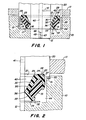
- a conventional type of link for a track-laying implement has one end offset axially with respect to an opposite end. When assembled, the outermost end of one link is positioned on the pin next to the innermost end of the adjoining link. Referring to Fig 1, the outer link end is shown at 10 and the inner link end is shown at 11.
- the links having the ends 10, 11 extend in opposite directions from and are pivotally connected at the adjoining link ends 10, 11 by a track pin 12 which extends through both ends 10, 11.
- the outer link end 10 has an annular recess 13 next to and concentric with the pin 12.
- the recess 13 opens toward the inner link end 11 and is made of an axially extending circumferential wall 14, a radial wall 15 and in part, by a washer 16 having a surface 17 against which the seal, as will later become apparent, rests.
- the surface 17 is hardened so as to resist wear.
- a track bushing 20 is mounted on the pin 12 and extends through, and is tightly gripped by, the inner link end 11 so as to oscillate with the link end 11.
- the track bushing 20 has an annular groove 21 at its end which is at the entry side of the recess 13.
- the groove 21 is made up of a radially extending wall 24 and an axially extending wall 23.
- the wall 23 forms an annular shoulder with the radial wall 24 at the base of the groove 21.
- the thrust bush 25 limits axial movement of the track bushing 20, as well as the pin 12.
- the flat surfaces between the edge of the thrust bush 25 and the edge of the track bushing 20 serve partly as a seal which prevents free flow of material into the area within the thrust ring 25.
- a seal assembly composed of a main annular seal member 30 and an annular load seal member 31.
- the primary seal member 30 is made of a relatively rigid abrasion-resistant material such as polyurethane, for example, while the seal member 31 is composed of a resilient, relatively pliant elastomeric material, such as rubber.
- the primary seal member 30 has a C-shaped interior which tends to grip or hold the secondary seal member 31.
- the primary seal member 30 has at one end a flat radial face 28 and a flat outer surface 27 that bear against and conform to the surface 23, 24 of the groove 21. Consequently, the shoulder formed by the walls 23 and 24 serves to limit or prevent radial and axial shifting of the primary seal member 30.
- the primary seal member 30 also has annular lip 29 radially inwardly of the surface 28 with a sharp annular edge in contact with the surface 24 of the groove 21.
- annular lip 29 At the opposite end of the primary seal member, there is provided a pair of diverging walls 32, 33 that form an annular lip 34 that bears against the surface 17 of the wear or thrust washer 16.
- the diverging wall 33 extends towards the pin 12 where it meets a second diverging wall 35 to form a lip 36.
- the lip 36 bears against the hardened outer surface of the pin 12.
- the two annular lips 34, 36 are held in engagement with the wall 17 and the surface of the pin 12 through the action of the forces in the load or secondary seal member 31.
- the member is composed of a more resilient type of material and is compressed in the interior of the C-shaped member 30 and tends to expand the annular seal member 30 so as to hold the lips 34, 36 in their proper position. Since the member 31 is radially outside the lips 34, 36, the forces are so directed as to force the lips into contact with pin 12 and the surface 17.
- the pin 12 has a hollow interior 40 that serves as a lubricant or oil reservoir. Oil passages 41 extend from the reservoir 40 to the area between the pin 12 and the track bushing 20.
- the two annular lips 34, 36 will generally prevent foreign matter from entering into the lubricant reservoir 42 and will likewise prevent leakage of oil in the lubricant reservoir 42 outwardly into the area 44 of the recess.
- the reservoir 40 at the centre of the pin 12 it is sealed by a rubber ring 45 with an axially extending bore 46 therein.
- Lubricant is introduced into the reservoir 40 through the axial bore 46 until the reservoirs 40 and 42 are full of lubricant.
- the bore 46 is then closed by a plug 47 that is inserted from outside of the link assembly.
- the outer link end 10 has an annular rebate 50 round the mouth of the recess 13. Seated in the rebate 50 is a noncorrosive thrust washer 51 that may be replaced upon it becoming worn or damaged. The end of the track bushing 20 bears against and rides on the thrust washer 51. Other than this novel manner of supporting the end of the track bushing 20, other portions of the entire assembly are the same, and consequently, similar reference numbers are used.
Landscapes
- Engineering & Computer Science (AREA)
- General Engineering & Computer Science (AREA)
- Mechanical Engineering (AREA)
- Chemical & Material Sciences (AREA)
- Combustion & Propulsion (AREA)
- Transportation (AREA)
- Sealing Devices (AREA)
- Vehicle Body Suspensions (AREA)
Applications Claiming Priority (2)
| Application Number | Priority Date | Filing Date | Title |
|---|---|---|---|
| US663722 | 1984-10-22 | ||
| US06/663,722 US4568090A (en) | 1984-10-22 | 1984-10-22 | Oil seal for lubricated tracks on a crawler tractor |
Publications (1)
| Publication Number | Publication Date |
|---|---|
| EP0183373A1 true EP0183373A1 (fr) | 1986-06-04 |
Family
ID=24663025
Family Applications (1)
| Application Number | Title | Priority Date | Filing Date |
|---|---|---|---|
| EP85307542A Withdrawn EP0183373A1 (fr) | 1984-10-22 | 1985-10-18 | Assemblage de patin de chenille pour véhicule à chenilles |
Country Status (3)
| Country | Link |
|---|---|
| US (1) | US4568090A (fr) |
| EP (1) | EP0183373A1 (fr) |
| JP (1) | JPS61102385A (fr) |
Families Citing this family (17)
| Publication number | Priority date | Publication date | Assignee | Title |
|---|---|---|---|---|
| FR2600741A1 (fr) * | 1986-06-24 | 1987-12-31 | Jade Sa | Garniture d'etancheite pour axes et pivots |
| US5527046A (en) * | 1994-12-15 | 1996-06-18 | Caterpillar Inc. | Seal assembly having resilient load rings |
| US5727095A (en) * | 1997-02-21 | 1998-03-10 | Setco Sales Co. | Bearing seal with uniform fluid purge |
| US6217219B1 (en) | 1997-02-21 | 2001-04-17 | Setco Sales Co. | Bearing seal with uniform fluid purge |
| US6086069A (en) * | 1997-08-27 | 2000-07-11 | Caterpillar Inc. | Metal ring seal |
| JP4116187B2 (ja) * | 1998-12-03 | 2008-07-09 | 日立建機株式会社 | 履帯 |
| US7121555B2 (en) * | 2001-03-22 | 2006-10-17 | Komatsu Ltd. | Seal assembly and crawler-track connection structure |
| US20050023897A1 (en) * | 2003-07-31 | 2005-02-03 | Anderton Peter W. | Method and apparatus for rebuilding track assembly |
| US7857323B1 (en) | 2006-02-24 | 2010-12-28 | Ti Group Automotive Systems, L.L.C. | Multi-piece seal |
| US7784637B2 (en) * | 2007-02-21 | 2010-08-31 | Ti Group Automotive Systems, L.L.C. | Multi-piece seal |
| US7854434B2 (en) | 2007-04-12 | 2010-12-21 | Ti Group Automotive Systems, L.L.C. | Ring seal with axially-opposed radially-offset seal beads |
| US7975870B2 (en) | 2007-08-29 | 2011-07-12 | Ti Group Automotive Systems, L.L.C. | Ring seal having sealing lobes |
| US7959239B2 (en) * | 2008-03-25 | 2011-06-14 | Caterpillar Inc. | Track assembly having wear inhibiting contact members |
| US8910815B2 (en) | 2008-04-14 | 2014-12-16 | Ti Group Automotive Systems, L.L.C. | Cover for fuel system component and method of making |
| US8419021B2 (en) * | 2008-10-31 | 2013-04-16 | Ti Group Automotive Systems, L.L.C. | Ring seal with insert |
| US8511760B2 (en) * | 2010-10-06 | 2013-08-20 | Gse Technologies, Llc | Roller bearing track bushing system |
| US20200079445A1 (en) * | 2018-09-11 | 2020-03-12 | Caterpillar Inc. | Lip Seal |
Citations (4)
| Publication number | Priority date | Publication date | Assignee | Title |
|---|---|---|---|---|
| US2906562A (en) * | 1955-07-19 | 1959-09-29 | Leo C Burgman | Track pin and bushing seal |
| DE2353892A1 (de) * | 1972-10-25 | 1974-05-09 | Caterpillar Tractor Co | Dichtung mit lastausgleichsring |
| US4209204A (en) * | 1978-08-08 | 1980-06-24 | Deere & Company | Two-piece seal for track chain joints |
| US4295654A (en) * | 1979-05-11 | 1981-10-20 | Kabushiki Kaisha Komatsu Seisakusho | Seal assembly for a linkage |
Family Cites Families (7)
| Publication number | Priority date | Publication date | Assignee | Title |
|---|---|---|---|---|
| IT1082306B (it) * | 1977-05-11 | 1985-05-21 | Italtractor | Guarnizione di tenuta con anello di spinta compensatore |
| JPS638548Y2 (fr) * | 1979-09-10 | 1988-03-14 | ||
| US4262914A (en) * | 1979-12-03 | 1981-04-21 | Caterpillar Tractor Co. | End face seal assembly |
| US4344629A (en) * | 1980-10-14 | 1982-08-17 | Smith International, Inc. | Self-lapping high speed seal with wear-in lip |
| WO1982003670A1 (fr) * | 1980-11-21 | 1982-10-28 | Harold L Reinsma | Assemblage de joints ayant un organe plastique annulaire d'etancheite avec une levre solidaire d'etancheite |
| US4426091A (en) * | 1982-05-10 | 1984-01-17 | J. I. Case Company | Track joint seal assembly with interlocked thrust ring |
| DE3321152C2 (de) * | 1983-06-11 | 1986-07-24 | Prädifa Präzisions-Dichtungs-Fabrik GmbH, 7120 Bietigheim-Bissingen | Dichtung für Spurkettengelenke von Kettenfahrzeugen |
-
1984
- 1984-10-22 US US06/663,722 patent/US4568090A/en not_active Expired - Fee Related
-
1985
- 1985-10-18 EP EP85307542A patent/EP0183373A1/fr not_active Withdrawn
- 1985-10-22 JP JP60236250A patent/JPS61102385A/ja active Pending
Patent Citations (4)
| Publication number | Priority date | Publication date | Assignee | Title |
|---|---|---|---|---|
| US2906562A (en) * | 1955-07-19 | 1959-09-29 | Leo C Burgman | Track pin and bushing seal |
| DE2353892A1 (de) * | 1972-10-25 | 1974-05-09 | Caterpillar Tractor Co | Dichtung mit lastausgleichsring |
| US4209204A (en) * | 1978-08-08 | 1980-06-24 | Deere & Company | Two-piece seal for track chain joints |
| US4295654A (en) * | 1979-05-11 | 1981-10-20 | Kabushiki Kaisha Komatsu Seisakusho | Seal assembly for a linkage |
Also Published As
| Publication number | Publication date |
|---|---|
| JPS61102385A (ja) | 1986-05-21 |
| US4568090A (en) | 1986-02-04 |
Similar Documents
| Publication | Publication Date | Title |
|---|---|---|
| US4568090A (en) | Oil seal for lubricated tracks on a crawler tractor | |
| US5887958A (en) | Track link assembly having positive pin retention | |
| US4094516A (en) | Track pin assemblies and seal therefor | |
| US4256315A (en) | Mechanical end face seal with dirt excluder lip | |
| CA1181107A (fr) | Etancheite pour paliers | |
| CA1125545A (fr) | Joint a rotule | |
| CA1265546A (fr) | Garniture souple d'etancheite pour joint spherique | |
| US4457521A (en) | Reinforced track pin assemblies and seals therefor | |
| US5763956A (en) | End face track seal with dirt seal | |
| US5794940A (en) | End face seal with sacrificial wear-in excluder | |
| US4062550A (en) | Seal assembly with backup ring | |
| EP0221585B1 (fr) | Assemblage de joint annulaire d'extrémité | |
| US4594846A (en) | Track joint and method of assembling same | |
| GB1576029A (en) | Track pin assemblies and seal therefor | |
| US4209204A (en) | Two-piece seal for track chain joints | |
| EP1214538B1 (fr) | Ensemble articulation a ressort conique encapsule | |
| US5899459A (en) | Track joint sealing assembly having a ceramic seal member and elastomeric spring members for sealing a track joint in a track chain | |
| US5685548A (en) | Seal for track-chain link having lubricant filled pockets | |
| CA1043381A (fr) | Etancheite symetrique pour joint a charniere | |
| EP0104753A2 (fr) | Joint avec assemblage d'étanchéité facial | |
| GB2095347A (en) | Seals | |
| CA1073685A (fr) | Articulation de chaine pour drague | |
| US4526377A (en) | Turn-over seal | |
| US4239297A (en) | Radial face seal | |
| JPH0725485Y2 (ja) | 履帯シール |
Legal Events
| Date | Code | Title | Description |
|---|---|---|---|
| PUAI | Public reference made under article 153(3) epc to a published international application that has entered the european phase |
Free format text: ORIGINAL CODE: 0009012 |
|
| AK | Designated contracting states |
Kind code of ref document: A1 Designated state(s): DE FR GB IT |
|
| 17P | Request for examination filed |
Effective date: 19860602 |
|
| 17Q | First examination report despatched |
Effective date: 19870127 |
|
| ITF | It: translation for a ep patent filed | ||
| STAA | Information on the status of an ep patent application or granted ep patent |
Free format text: STATUS: THE APPLICATION IS DEEMED TO BE WITHDRAWN |
|
| 18D | Application deemed to be withdrawn |
Effective date: 19880502 |
|
| RIN1 | Information on inventor provided before grant (corrected) |
Inventor name: WESTEMEIER, DONALD EDMUND |