EP0183864A1 - Assemblage d'au moins deux fermes à plusieurs poutres, essentiellement horizontales, suspendues à ces fermes et assurées contre le risque d'enlèvement - Google Patents
Assemblage d'au moins deux fermes à plusieurs poutres, essentiellement horizontales, suspendues à ces fermes et assurées contre le risque d'enlèvement Download PDFInfo
- Publication number
- EP0183864A1 EP0183864A1 EP84114734A EP84114734A EP0183864A1 EP 0183864 A1 EP0183864 A1 EP 0183864A1 EP 84114734 A EP84114734 A EP 84114734A EP 84114734 A EP84114734 A EP 84114734A EP 0183864 A1 EP0183864 A1 EP 0183864A1
- Authority
- EP
- European Patent Office
- Prior art keywords
- purlin
- bracket
- fork
- locking
- locking bracket
- Prior art date
- Legal status (The legal status is an assumption and is not a legal conclusion. Google has not performed a legal analysis and makes no representation as to the accuracy of the status listed.)
- Granted
Links
- 239000000725 suspension Substances 0.000 claims abstract description 6
- 239000011230 binding agent Substances 0.000 claims description 13
- 230000001154 acute effect Effects 0.000 claims description 3
- 230000004048 modification Effects 0.000 claims 1
- 238000012986 modification Methods 0.000 claims 1
- 238000010276 construction Methods 0.000 abstract description 2
- 230000001174 ascending effect Effects 0.000 abstract 1
- 230000000284 resting effect Effects 0.000 abstract 1
- 229910000831 Steel Inorganic materials 0.000 description 1
- XAGFODPZIPBFFR-UHFFFAOYSA-N aluminium Chemical compound [Al] XAGFODPZIPBFFR-UHFFFAOYSA-N 0.000 description 1
- 229910052782 aluminium Inorganic materials 0.000 description 1
- 238000009412 basement excavation Methods 0.000 description 1
- 239000002131 composite material Substances 0.000 description 1
- 238000003780 insertion Methods 0.000 description 1
- 230000037431 insertion Effects 0.000 description 1
- 230000003014 reinforcing effect Effects 0.000 description 1
- 239000010959 steel Substances 0.000 description 1
Images




Classifications
-
- E—FIXED CONSTRUCTIONS
- E04—BUILDING
- E04H—BUILDINGS OR LIKE STRUCTURES FOR PARTICULAR PURPOSES; SWIMMING OR SPLASH BATHS OR POOLS; MASTS; FENCING; TENTS OR CANOPIES, IN GENERAL
- E04H15/00—Tents or canopies, in general
- E04H15/32—Parts, components, construction details, accessories, interior equipment, specially adapted for tents, e.g. guy-line equipment, skirts, thresholds
- E04H15/34—Supporting means, e.g. frames
-
- E—FIXED CONSTRUCTIONS
- E04—BUILDING
- E04B—GENERAL BUILDING CONSTRUCTIONS; WALLS, e.g. PARTITIONS; ROOFS; FLOORS; CEILINGS; INSULATION OR OTHER PROTECTION OF BUILDINGS
- E04B1/00—Constructions in general; Structures which are not restricted either to walls, e.g. partitions, or floors or ceilings or roofs
- E04B1/343—Structures characterised by movable, separable, or collapsible parts, e.g. for transport
- E04B1/34315—Structures characterised by movable, separable, or collapsible parts, e.g. for transport characterised by separable parts
- E04B1/34326—Structures characterised by movable, separable, or collapsible parts, e.g. for transport characterised by separable parts mainly constituted by longitudinal elements
Definitions
- the invention relates to a connection of at least two roof trusses with a plurality of substantially horizontal purlins, which are each formed at their two ends with downward-facing support hooks which engage in the hanging tabs fastened with the roof trusses and are secured against unintentional lifting out of the Hanging brackets are secured, especially for the creation of tent scaffolding.
- a securing of the connecting purlins against undesired lifting out of the hanging tabs connected to the binder is generally achieved in that at the lower end of the leg of the carrying hook facing the binder, below the tab, there is a hole for receiving an engaging in the binder Locking pin is provided.
- DE-GM 83 10 306 secures the connection between the purlins in a supporting structure for a tent by providing a safety bracket on at least one end of each purlin, which is pivotally connected to the purlin about an axis running transversely to the longitudinal axis of the purlin and which engages under the hanging tab.
- a disadvantage of this design is that the locking mechanism does not engage in the hanging tab, but extends over it from the outside. This means that at e.g. always possible assembly failure, resulting inclined position of the vertical axis of the girder profile, there is a risk of lifting the hold-up bar.
- a fixation of the hook position to the truss can in no way be ensured by such a hold-up bar.
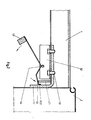
- the purlin has in its end regions a bracket joint which is carried outside the purlin cross section and extends transversely to the purlin longitudinal extension and parallel to the purlin floor at a predetermined distance and is provided with a pivotable locking bracket, that the locking bracket with its end facing away from the truss is made heavier than the bracket end pointing towards the hanging tab and is bent so that in the locked position the bracket end runs approximately parallel to the hook at a distance leading to zero and the subsequent angling of the locking bracket rests against the inner edge of the hanging tab , and that the angle between the temple end and the subsequent bend by or over 90 °, and the further bend leading to the bend joint is designed to rise, while the overweight end, relative to the purlin plane, is angled downwards, and the end region as a fork stop for a purlin fork is formed.
- the positive engagement of the locking bracket in the hook-in tab connected to the purlin provides both a safe, simple locking and a reduction in the play of the purlin in its longitudinal extent between the binders.
- the fork itself is formed by a U-profile that is connected to the bottom of the purlin, it is expedient that the U-profile forming the fork is screwed to the part of the hook that reaches into the purlin, including the bottom of the purlin.
- the overweight end of the locking bracket is provided with a weight piece arranged on the top, and that the overweight end, based on the level of the purlin, angled downwards, and the end region is designed as a fork stop for a lifting fork.
- the fork stop for the lifting fork which is formed by a bend, can be made relatively short.
- the locking position should be summarized again, the criterion of which is that at the stroke of the purlin locked in the mounting bracket, the end of the bracket rests against the hook at an acute angle, and the angling of the locking bracket downward lies on the surface or line delimiting the thickness of the mounting bracket and is essentially plane-parallel or parallel.
- the purlin is only equipped on one side with a locking bracket which is rotatably arranged on a bracket joint.
- the bearing fork formed by a U-shaped profile 1.2 for receiving the bow joint 1.4 is connected from below to the purlin floor by screws 1.9, which in turn engage in corresponding threads of the inside hook 1.1.
- the fork width i.e. the distance between the U-legs corresponds, with some play, the width of the pivotable locking bracket 1.3.
- the position of the bow joint 1.4 is determined so that the shorter, i.e. the less important part of the bracket 1.3 with its bracket end 1.31 is directed approximately parallel against the hook 1.1, and with its bend 1.32, which is slightly more than 90 ° below, rests against the inner edge of the bracket 2.1 and the further bend 1.33 leads to the bracket joint 1.4.
- the subsequent overweight end 1.34 leads into a fork stop 1.5 which reinforces the overweight and is angled by 90 °, this additionally reinforcing the excess weight.
- the bracket end 1.31 lies at an acute angle on the hook surface, while the angling 1.32 of the locking bracket 1.3 downwards essentially delimits the surface or line formed by the thickness of the hooking tabs 2.1 lies plane-parallel or parallel.
- FIG. 4 If the overweight end of the locking bracket 1.3 is raised by a lifting fork 3, FIG. 4, then, as an embodiment according to FIG. 1 shows in the unlocked position, the purlin can be easily lifted by the lifting fork 3.
- Figure 2 shows the equipment of the temple end 1.34 with a separate, downward weight 1.7, which can also take over the function of the fork stop.
- the bow end 1.34 is designed with an upward weight 1.8, the section 1.34, similar to that in FIG. 1, being transferred to a stop 1.6, which, however, can be kept shorter than stop 1.5 in FIG. 1 as a result of the additional weight.
- the trusses and purlins are usually extruded aluminum profiles, while the hanging tabs and hooks, as well as the locking mechanism, are preferably made of steel.
Landscapes
- Engineering & Computer Science (AREA)
- Architecture (AREA)
- Civil Engineering (AREA)
- Structural Engineering (AREA)
- Physics & Mathematics (AREA)
- Electromagnetism (AREA)
- Conveying And Assembling Of Building Elements In Situ (AREA)
- Joining Of Building Structures In Genera (AREA)
- Fittings On The Vehicle Exterior For Carrying Loads, And Devices For Holding Or Mounting Articles (AREA)
- Tents Or Canopies (AREA)
Priority Applications (3)
| Application Number | Priority Date | Filing Date | Title |
|---|---|---|---|
| AT84114734T ATE33511T1 (de) | 1984-12-04 | 1984-12-04 | Verbindung von mindestens zwei dachbindern mit mehreren, im wesentlichen horizontal verlaufenden, and den dachbindern eingehaengten, aushubsicherbaren pfetten. |
| EP84114734A EP0183864B1 (fr) | 1984-12-04 | 1984-12-04 | Assemblage d'au moins deux fermes à plusieurs poutres, essentiellement horizontales, suspendues à ces fermes et assurées contre le risque d'enlèvement |
| DE8484114734T DE3470427D1 (en) | 1984-12-04 | 1984-12-04 | Connection of at least two roof trusses with several, essentially horizontally disposed purlins suspended from the trusses and secured against protusion |
Applications Claiming Priority (1)
| Application Number | Priority Date | Filing Date | Title |
|---|---|---|---|
| EP84114734A EP0183864B1 (fr) | 1984-12-04 | 1984-12-04 | Assemblage d'au moins deux fermes à plusieurs poutres, essentiellement horizontales, suspendues à ces fermes et assurées contre le risque d'enlèvement |
Publications (2)
| Publication Number | Publication Date |
|---|---|
| EP0183864A1 true EP0183864A1 (fr) | 1986-06-11 |
| EP0183864B1 EP0183864B1 (fr) | 1988-04-13 |
Family
ID=8192329
Family Applications (1)
| Application Number | Title | Priority Date | Filing Date |
|---|---|---|---|
| EP84114734A Expired EP0183864B1 (fr) | 1984-12-04 | 1984-12-04 | Assemblage d'au moins deux fermes à plusieurs poutres, essentiellement horizontales, suspendues à ces fermes et assurées contre le risque d'enlèvement |
Country Status (3)
| Country | Link |
|---|---|
| EP (1) | EP0183864B1 (fr) |
| AT (1) | ATE33511T1 (fr) |
| DE (1) | DE3470427D1 (fr) |
Cited By (1)
| Publication number | Priority date | Publication date | Assignee | Title |
|---|---|---|---|---|
| CN117051852A (zh) * | 2023-07-25 | 2023-11-14 | 中国一冶集团有限公司 | 一种硬塑回填土层钢板桩支护结构及其施工方法 |
Citations (3)
| Publication number | Priority date | Publication date | Assignee | Title |
|---|---|---|---|---|
| US2588905A (en) * | 1950-03-07 | 1952-03-11 | Universal Mfg Co | Scaffold bracing |
| BE716097A (fr) * | 1967-06-07 | 1968-11-04 | ||
| EP0032402A2 (fr) * | 1980-01-15 | 1981-07-22 | SGB public limited company | Système d'échafaudage |
-
1984
- 1984-12-04 AT AT84114734T patent/ATE33511T1/de not_active IP Right Cessation
- 1984-12-04 EP EP84114734A patent/EP0183864B1/fr not_active Expired
- 1984-12-04 DE DE8484114734T patent/DE3470427D1/de not_active Expired
Patent Citations (3)
| Publication number | Priority date | Publication date | Assignee | Title |
|---|---|---|---|---|
| US2588905A (en) * | 1950-03-07 | 1952-03-11 | Universal Mfg Co | Scaffold bracing |
| BE716097A (fr) * | 1967-06-07 | 1968-11-04 | ||
| EP0032402A2 (fr) * | 1980-01-15 | 1981-07-22 | SGB public limited company | Système d'échafaudage |
Cited By (1)
| Publication number | Priority date | Publication date | Assignee | Title |
|---|---|---|---|---|
| CN117051852A (zh) * | 2023-07-25 | 2023-11-14 | 中国一冶集团有限公司 | 一种硬塑回填土层钢板桩支护结构及其施工方法 |
Also Published As
| Publication number | Publication date |
|---|---|
| DE3470427D1 (en) | 1988-05-19 |
| EP0183864B1 (fr) | 1988-04-13 |
| ATE33511T1 (de) | 1988-04-15 |
Similar Documents
| Publication | Publication Date | Title |
|---|---|---|
| DE68909281T2 (de) | Verstellbare Säule für ein Lastkraftfahrzeug mit verschiebbarer Abdeckung. | |
| DD259218A5 (de) | Transportable konstruktion, geeignet zum aufbau von haeusern und dergleichen | |
| DE102009061819B4 (de) | Auslegerelement für ein Hebezeug | |
| EP0211172B1 (fr) | Faux plafond | |
| DE69600926T2 (de) | Gitterträger für tragende geländer von hängebühne | |
| WO2018219851A1 (fr) | Plate-forme supplémentaire ajoutée à une plate-forme de travail | |
| EP0183864B1 (fr) | Assemblage d'au moins deux fermes à plusieurs poutres, essentiellement horizontales, suspendues à ces fermes et assurées contre le risque d'enlèvement | |
| DE20214938U1 (de) | Fassadensystem aus keramischen Fassadenplatten zum Einsatz als vorgehängte hinterlüftete Fassade an einer tragenden Bauwerkswand | |
| EP1953068B1 (fr) | Ranche pour constructions automobiles | |
| DE3306701A1 (de) | Sicherheitsdachhaken mit befestigungsvorrichtung | |
| DE3526288C2 (fr) | ||
| DE2851941C2 (de) | An der Abbaustoßseite eines Strebfördermittels befestigte Maschinenfahrbahn für Walzenschrämmaschinen | |
| DE3219572A1 (de) | Dachhaken | |
| DE2334308A1 (de) | Vorrichtung zum anhaengen eines sportgeraetes, transportgeraetes od. dgl. an das schleppseil eines schleppliftes | |
| DE3723706A1 (de) | Ladewagen | |
| EP2627828A2 (fr) | Assemblage d'éléments, structure porteuse, en particulier pont, et procédé d'assemblage d'éléments | |
| DE69322098T2 (de) | Abklappbare revisionsabdeckung | |
| DE3936905C1 (en) | Mine cage suspension system - incorporates adaptors to allow length adjustment | |
| EP0122615A2 (fr) | Porte basculante | |
| DE102023108085A1 (de) | Dachfenster und Scharniersystem für Dachfenster. | |
| DE202024100989U1 (de) | Schirmvorrichtung für ein Gewächshaus | |
| DE8534426U1 (de) | Halterung zum Befestigen von Blumenkästen an Schrägflächen | |
| DE2145021B2 (de) | Dachbindereinheit für Winterbauhallen | |
| DE8310306U1 (de) | Traggeruest fuer ein zelt od. dgl. | |
| DE8412239U1 (de) | Karosserieaufbau fuer lastkraftwagen oder anhaenger od. dgl. |
Legal Events
| Date | Code | Title | Description |
|---|---|---|---|
| PUAI | Public reference made under article 153(3) epc to a published international application that has entered the european phase |
Free format text: ORIGINAL CODE: 0009012 |
|
| 17P | Request for examination filed |
Effective date: 19851202 |
|
| AK | Designated contracting states |
Kind code of ref document: A1 Designated state(s): AT BE CH DE FR GB IT LI LU NL SE |
|
| RBV | Designated contracting states (corrected) |
Designated state(s): AT BE CH DE FR GB IT LI NL SE |
|
| 17Q | First examination report despatched |
Effective date: 19870326 |
|
| GRAA | (expected) grant |
Free format text: ORIGINAL CODE: 0009210 |
|
| AK | Designated contracting states |
Kind code of ref document: B1 Designated state(s): AT BE CH DE FR GB IT LI NL SE |
|
| REF | Corresponds to: |
Ref document number: 33511 Country of ref document: AT Date of ref document: 19880415 Kind code of ref document: T |
|
| ITF | It: translation for a ep patent filed | ||
| REF | Corresponds to: |
Ref document number: 3470427 Country of ref document: DE Date of ref document: 19880519 |
|
| GBT | Gb: translation of ep patent filed (gb section 77(6)(a)/1977) | ||
| ET | Fr: translation filed | ||
| ITTA | It: last paid annual fee | ||
| PGFP | Annual fee paid to national office [announced via postgrant information from national office to epo] |
Ref country code: BE Payment date: 19890111 Year of fee payment: 5 |
|
| PLBE | No opposition filed within time limit |
Free format text: ORIGINAL CODE: 0009261 |
|
| STAA | Information on the status of an ep patent application or granted ep patent |
Free format text: STATUS: NO OPPOSITION FILED WITHIN TIME LIMIT |
|
| PGFP | Annual fee paid to national office [announced via postgrant information from national office to epo] |
Ref country code: DE Payment date: 19890227 Year of fee payment: 5 |
|
| 26N | No opposition filed | ||
| PG25 | Lapsed in a contracting state [announced via postgrant information from national office to epo] |
Ref country code: GB Effective date: 19891204 Ref country code: AT Effective date: 19891204 |
|
| PG25 | Lapsed in a contracting state [announced via postgrant information from national office to epo] |
Ref country code: SE Effective date: 19891205 |
|
| PG25 | Lapsed in a contracting state [announced via postgrant information from national office to epo] |
Ref country code: LI Effective date: 19891231 Ref country code: CH Effective date: 19891231 Ref country code: BE Effective date: 19891231 |
|
| BERE | Be: lapsed |
Owner name: RODER EDWIN Effective date: 19891231 |
|
| PG25 | Lapsed in a contracting state [announced via postgrant information from national office to epo] |
Ref country code: NL Effective date: 19900701 |
|
| GBPC | Gb: european patent ceased through non-payment of renewal fee | ||
| NLV4 | Nl: lapsed or anulled due to non-payment of the annual fee | ||
| PG25 | Lapsed in a contracting state [announced via postgrant information from national office to epo] |
Ref country code: FR Effective date: 19900831 |
|
| REG | Reference to a national code |
Ref country code: CH Ref legal event code: PL |
|
| PG25 | Lapsed in a contracting state [announced via postgrant information from national office to epo] |
Ref country code: DE Effective date: 19900901 |
|
| REG | Reference to a national code |
Ref country code: FR Ref legal event code: ST |
|
| EUG | Se: european patent has lapsed |
Ref document number: 84114734.1 Effective date: 19900830 |