EP0183974A1 - Tête de détection des défauts de surfaces de contreplaqué - Google Patents
Tête de détection des défauts de surfaces de contreplaqué Download PDFInfo
- Publication number
- EP0183974A1 EP0183974A1 EP85113640A EP85113640A EP0183974A1 EP 0183974 A1 EP0183974 A1 EP 0183974A1 EP 85113640 A EP85113640 A EP 85113640A EP 85113640 A EP85113640 A EP 85113640A EP 0183974 A1 EP0183974 A1 EP 0183974A1
- Authority
- EP
- European Patent Office
- Prior art keywords
- plywood
- optical fiber
- shielding plate
- light
- concave
- Prior art date
- Legal status (The legal status is an assumption and is not a legal conclusion. Google has not performed a legal analysis and makes no representation as to the accuracy of the status listed.)
- Granted
Links
Images

Classifications
-
- G—PHYSICS
- G01—MEASURING; TESTING
- G01B—MEASURING LENGTH, THICKNESS OR SIMILAR LINEAR DIMENSIONS; MEASURING ANGLES; MEASURING AREAS; MEASURING IRREGULARITIES OF SURFACES OR CONTOURS
- G01B11/00—Measuring arrangements characterised by the use of optical techniques
- G01B11/30—Measuring arrangements characterised by the use of optical techniques for measuring roughness or irregularity of surfaces
-
- G—PHYSICS
- G01—MEASURING; TESTING
- G01N—INVESTIGATING OR ANALYSING MATERIALS BY DETERMINING THEIR CHEMICAL OR PHYSICAL PROPERTIES
- G01N21/00—Investigating or analysing materials by the use of optical means, i.e. using sub-millimetre waves, infrared, visible or ultraviolet light
- G01N21/84—Systems specially adapted for particular applications
- G01N21/88—Investigating the presence of flaws or contamination
- G01N21/89—Investigating the presence of flaws or contamination in moving material, e.g. running paper or textiles
- G01N21/892—Investigating the presence of flaws or contamination in moving material, e.g. running paper or textiles characterised by the flaw, defect or object feature examined
- G01N21/898—Irregularities in textured or patterned surfaces, e.g. textiles, wood
- G01N21/8986—Wood
-
- G—PHYSICS
- G01—MEASURING; TESTING
- G01N—INVESTIGATING OR ANALYSING MATERIALS BY DETERMINING THEIR CHEMICAL OR PHYSICAL PROPERTIES
- G01N2201/00—Features of devices classified in G01N21/00
- G01N2201/10—Scanning
- G01N2201/108—Miscellaneous
- G01N2201/1085—Using optical fibre array and scanner
Definitions
- This invention relates to a plywood surface defect detecting head of the type used for detecting defects attributable to, for example, knot holes of original plates, worm holes, cracks, and the like, which exist in the surface of plywood.
- the applicant of the present invention has proposed in his prior Japanese Patent Application No. 59-188649 a detector for detecting concave-shaped defects in the surface of a plate-like member comprising a shielding member slidingly contacting the surface of a plate-like member at its front end, a moving mechanism for relatively moving the shielding member and the plate-like member, a light source disposed at one side of the shielding member, a number of light receiving elements disposed at the other side of the shielding member with required spaces according to capability of detection and resolution, and a control circuit for detecting the concave-shaped defects in the plate-like member based on light radiated toward the light receiving elements from the light source through a concave-shaped portion in the surface of the plate-like member when the shielding member is positioned in the concave-shaped portion according to the relative movement of the shielding
- the present invention was accomplished in order to overcome the problems inherent in the prior art.
- a plywood surface defect detecting head comprising a shielding plate slidingly contacted at its front end with one surface of the plywood, a light source provided at one side of the shielding plate, and an optical fiber provided at the other side of the shielding plate, the optical fiber being disposed as such that one end thereof slidingly contacts the plywood surface together with the shielding plate and the other end thereof faces toward a light detector.
- the front end of a shielding plate and one end of an optical fiber both slidingly contact the surface of plywood according to the relative movement of a detecting head and the surface of the plywood.
- the shielding plate When concave-shaped defects existing in the surface of the plywood pass the shielding plate, light radiated from a light source passes the defects and immediately enters the optical fiber from one end thereof. And, the other end of the optical fiber projects the light toward the light detector.
- Fig. 1 denotes a plywood movable in the direction as shown by an arrow
- 2 denotes a shielding plate
- 4 denotes a light source
- 3 denotes an optical fiber.
- the optical fiber 3 has 31 fibers. Constitution of the embodiment is such that concave-shaped defects (not shown) can be detected at desired spaces throughout the whole width of the plywood 1.
- 5 denotes an optical detector having a CCD image sensor.
- VIDEO MEASURE manufacturer manufactured by T ateishi Denki Kabushiki Kaisha.
- the optical fiber both of a glass system and a plastic system. In this embodiment, the cheap priced plastic system can serve the purpose.
- ESKA compoundchandise name
- Mitsubishi Rayon Kabushiki Kaisha When may fibers are used as the present case is, it is convenient to use ESKA OPTICAL SHEET (merchandise name).
- a metallic leaf spring is suitable for the shielding palte 2.
- the thickness of the sliding portion thereof is determined based on the minimum dimension of a concave-shaped defect to be detected. From a view point of general use, it is preferably formed of a leaf spring having a thickness of about 0.1 to 4mm in order to manufacture it at a low cost.
- the shielding plate 2 is not limited to metal. Instead, there may be used such materials as plastics, rubbers, and the like.
- the front end of the plate 2 slidingly contacting the plywood 1 should be formed of an elastic material so that it can be deformed according to undulation (wave) of the surface of the plywood 1.
- Fig. 2 illustrates an enlarged view of part of Fig. 1.
- la denotes a concave-shaped defect of the plywood 1, and light emitted from a light source (not shown, but the radiating direction of the light is shown by an arrow) provided at the left side of the shielding plate 2 passes through the defect la and enters in an optical fiber 3 from one end 3a thereof.
- Supposing the defect la is a worm hole existing in an original plate of the plywood 1, among 31 optical fibers 3 in Fig. 1, only a fiber having one end at an upper location of the defect la projects a strong light toward a light detector 5 from the other end 3b thereof.
- the detector 5 detects and treats the concave-shaped defect la due to the worm hole according to the difference of light and shade between the fore-mentioned other end 3b and the other ends of the remaining optical fibers.
- the defects can also be detected in the same manner as the concave-shaped defects by detecting light passed through one side or both sides of the defects.
- Fig. 3 illustrates one example of the optical fiber 3, wherein a part of one end 3a of the fiber 3 is not in slided contact with the surface of the plywood 1. Even in this case, since the remaining part is in slided contact with the surface, it is also included in the present embodiment. In the case of this example, both the shielding plate 2 and the optical fiber 3 are in slided contact with the surface of the plywood 1. Accordingly, they are gradually worn and become a state shown in Fig. 2.
- Fig. 4 illustrates one example wherein the example of Fig. 2 is added with a wear adjusting plate 6 slidingly contacts the surface of the plywood 1 moving in the direction as shown by an arrow, together with the shielding plate 2 and the optical fiber 3.
- the addition of the plate 6 enables to properly adjust the wear of the optical fiber 3.
- Fig. 5 illustrates an optical fiber 3 which is not an embodiment of the present invention, and one end 3a of which is disposed in a manner spaced apart from the surface of the plywood.
- a dust 7 such as wood powder and sander powder attaches one end 3a of optical fiber 3, which i decreases incidient efficacy of the light.
- the light passed through the concave-shaped defect la is dispersed and thereafter enters the optical fiber 3 from one end 3a thereof. Accordingly, since the light also enters the remaining optical fibers adjacent thereto, capability of detection and resolve is decreased extensively.
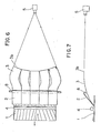
- Figs. 6 and 7 illustrate in a shape of a plan view and a front view an example of a plywood having a wide width to which the present invention is applied.
- the whole width of the plywood 1 is divided into five portions, and five shielding plates 2 are swingably disposed on a supporting point shaft 8, so that the front end thereof can more flexibly follow the undulation of the plywood 1.
- the optical fiber 3 is formed of a number of fibers formed in a sheet- shape of densed linear fibers which are integrally attached to the front end portions of the respective shielding plates 2.
- the other ends 3b for projecting the light toward the light detector are bent per each unit, as shown in the figures. In this way, when one including a lens optical system is employed as the light detector, objective distance can be adjusted according to necessity to obtain a favorable focusing.
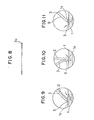
- the optical fiber 3 is disposed with the other end 3b facing the light detector 5 as shown in Fig. 8. Every time the concave-shaped defect passes, some of the number of optical fibers project a strong light, thereby enabling to detect the defect, its size, and its position.
- Figs. 9 through 11 illustrate modified embodiments relating to disposition of shielding plate 2, optical fiber 3, and the light source.
- a light source disposed at the initial position are a light source, then shielding plate 2, and optical fiber 3 in this order.
- anglewise alternation is applied.
- the emboidment in Figs. 2 through 4 may be constituted by reversing the progressing direction of plywood 1.
- at least at the light source side a coating film may be formed, or otherwise various kinds of plastic resins may be attached thinly to form substantial shielding plate 9.
- the light detector there are well known detectors other than the one shown by way of example. They can be selectively used according to necessity. Depending on what type of detector is used, the other end 3b of the optical fiber can be suitably optically connected to the light detector.
- the present invention is simple in its constitution, and yet can detect a defect existing in the surface of plywood without dispersing the light passed through the defect. Accordingly, an extremely satisfactory detection can be obtained.
- one end of the optical fiber is in slided contact with the surface of the plywood, attachment of dusts or the like is very few.
- a satisfactory wear surface (which corresponds to the grinding surface since the object is wood) can be always maintained, and an extremely favorable transmission efficiency can be obtained. Accordingly, this invention will be sure to contribute to automation of detection of a defect in inspection process, filing treatment process, etc. of plywood, and also to the plywood industry.
Landscapes
- Life Sciences & Earth Sciences (AREA)
- Engineering & Computer Science (AREA)
- Wood Science & Technology (AREA)
- Textile Engineering (AREA)
- Physics & Mathematics (AREA)
- General Physics & Mathematics (AREA)
- Biochemistry (AREA)
- Analytical Chemistry (AREA)
- Chemical & Material Sciences (AREA)
- General Health & Medical Sciences (AREA)
- Health & Medical Sciences (AREA)
- Immunology (AREA)
- Pathology (AREA)
- Investigating Materials By The Use Of Optical Means Adapted For Particular Applications (AREA)
- Length Measuring Devices By Optical Means (AREA)
- Veneer Processing And Manufacture Of Plywood (AREA)
- Optical Fibers, Optical Fiber Cores, And Optical Fiber Bundles (AREA)
- Light Guides In General And Applications Therefor (AREA)
Applications Claiming Priority (2)
| Application Number | Priority Date | Filing Date | Title |
|---|---|---|---|
| JP59228759A JPS61107106A (ja) | 1984-10-30 | 1984-10-30 | 合板表面の欠点検出ヘツド |
| JP228759/84 | 1984-10-30 |
Publications (2)
| Publication Number | Publication Date |
|---|---|
| EP0183974A1 true EP0183974A1 (fr) | 1986-06-11 |
| EP0183974B1 EP0183974B1 (fr) | 1989-01-25 |
Family
ID=16881379
Family Applications (1)
| Application Number | Title | Priority Date | Filing Date |
|---|---|---|---|
| EP85113640A Expired EP0183974B1 (fr) | 1984-10-30 | 1985-10-26 | Tête de détection des défauts de surfaces de contreplaqué |
Country Status (8)
| Country | Link |
|---|---|
| US (1) | US4738533A (fr) |
| EP (1) | EP0183974B1 (fr) |
| JP (1) | JPS61107106A (fr) |
| KR (1) | KR900005643B1 (fr) |
| CN (1) | CN85109002B (fr) |
| CA (1) | CA1254969A (fr) |
| DE (1) | DE3567969D1 (fr) |
| FI (1) | FI854231L (fr) |
Cited By (3)
| Publication number | Priority date | Publication date | Assignee | Title |
|---|---|---|---|---|
| WO1991010127A1 (fr) * | 1988-12-27 | 1991-07-11 | Eastman Kodak Company | Dispositif d'exploration et d'analyse d'une bande |
| WO1996009533A1 (fr) * | 1994-09-19 | 1996-03-28 | Robert Ernest Van Ditmar | Procede et installation de detection de variations de couleur dans une bande de materiau |
| EP0909948A3 (fr) * | 1997-10-17 | 1999-06-09 | STN ATLAS Elektronik GmbH | Procédé pour la détection de fissures dans des surfaces de bois dur |
Families Citing this family (11)
| Publication number | Priority date | Publication date | Assignee | Title |
|---|---|---|---|---|
| JPS63181949U (fr) * | 1987-05-15 | 1988-11-24 | ||
| GB8718073D0 (en) * | 1987-07-30 | 1987-09-03 | King J T | Surface inspection lighting scheme |
| US5220617A (en) * | 1991-09-04 | 1993-06-15 | International Business Machines Corporation | Method and apparatus for object inspection |
| US5216485A (en) * | 1991-09-04 | 1993-06-01 | International Business Machines Corporation | Advanced via inspection tool (avit) |
| US6757058B1 (en) * | 1999-05-05 | 2004-06-29 | Lucidyne Technologies, Inc. | Fiber-optic light line for use in an inspection system |
| WO2008036839A2 (fr) * | 2006-09-20 | 2008-03-27 | Lucidyne Technologies, Inc. | Capteur d'angle de grain |
| WO2011121694A1 (fr) * | 2010-03-31 | 2011-10-06 | 株式会社 日立ハイテクノロジーズ | Dispositif d'essai et procédé d'essai |
| CN102765113A (zh) * | 2012-07-27 | 2012-11-07 | 史尧锋 | 胶合板全自动刮腻子机 |
| CN107505335B (zh) * | 2017-09-05 | 2022-08-02 | 天之域电子工业(厦门)有限公司 | 一种触摸屏贴合气泡的检测装置及方法 |
| CN109176769A (zh) * | 2018-08-23 | 2019-01-11 | 湖州华尚家具有限公司 | 一种精确的木板表面腻子填补器 |
| CN111086071B (zh) * | 2018-10-24 | 2021-11-26 | 株式会社名南制作所 | 单板移动装置 |
Citations (2)
| Publication number | Priority date | Publication date | Assignee | Title |
|---|---|---|---|---|
| US3120861A (en) * | 1960-07-14 | 1964-02-11 | Western Pine Ass | Method and apparatus for identifying and evaluating surface characteristics of forest products |
| US3890509A (en) * | 1972-05-09 | 1975-06-17 | Black Clawson Co | Automatic edger set works method and apparatus |
Family Cites Families (3)
| Publication number | Priority date | Publication date | Assignee | Title |
|---|---|---|---|---|
| US4029391A (en) * | 1974-08-22 | 1977-06-14 | Sterndent Corporation | Light probe and interface therefor |
| US4338032A (en) * | 1979-05-18 | 1982-07-06 | Spencer Wright Industries, Inc. | Detection of faults in sheet and like materials |
| JPS6165147A (ja) * | 1984-09-06 | 1986-04-03 | Meinan Mach Works Inc | 板状体表面の凹状欠点検出装置 |
-
1984
- 1984-10-30 JP JP59228759A patent/JPS61107106A/ja active Pending
-
1985
- 1985-10-26 DE DE8585113640T patent/DE3567969D1/de not_active Expired
- 1985-10-26 EP EP85113640A patent/EP0183974B1/fr not_active Expired
- 1985-10-28 FI FI854231A patent/FI854231L/fi not_active Application Discontinuation
- 1985-10-29 CN CN85109002A patent/CN85109002B/zh not_active Expired
- 1985-10-29 CA CA000494170A patent/CA1254969A/fr not_active Expired
- 1985-10-29 US US06/792,682 patent/US4738533A/en not_active Expired - Fee Related
- 1985-10-30 KR KR1019850008057A patent/KR900005643B1/ko not_active Expired
Patent Citations (2)
| Publication number | Priority date | Publication date | Assignee | Title |
|---|---|---|---|---|
| US3120861A (en) * | 1960-07-14 | 1964-02-11 | Western Pine Ass | Method and apparatus for identifying and evaluating surface characteristics of forest products |
| US3890509A (en) * | 1972-05-09 | 1975-06-17 | Black Clawson Co | Automatic edger set works method and apparatus |
Non-Patent Citations (3)
| Title |
|---|
| APPLIED OPTICS, vol. 21, no. 19, October 1982, pages 3531-3535, New York, US; P.C.F. BORSBOOM et al.: "Fiber-optic scattering monitor for use with bulk opaque material" * |
| IBM TECHNICAL DISCLOSURE BULLETIN, vol. 22, no. 10, March 1980, pages 4528-4529, Armonk, New York, US; F. CRISAFI "Detection of underfilled holes in a ceramic sheet" * |
| PATENT ABSTRACTS OF JAPAN, vol. 5, no. 56 (P-57)[728], 17th April 1981, New York, US; & JP-A-56 008 531 (MATSUSHITA DENKO K.K.) 28-01-1981 * |
Cited By (3)
| Publication number | Priority date | Publication date | Assignee | Title |
|---|---|---|---|---|
| WO1991010127A1 (fr) * | 1988-12-27 | 1991-07-11 | Eastman Kodak Company | Dispositif d'exploration et d'analyse d'une bande |
| WO1996009533A1 (fr) * | 1994-09-19 | 1996-03-28 | Robert Ernest Van Ditmar | Procede et installation de detection de variations de couleur dans une bande de materiau |
| EP0909948A3 (fr) * | 1997-10-17 | 1999-06-09 | STN ATLAS Elektronik GmbH | Procédé pour la détection de fissures dans des surfaces de bois dur |
Also Published As
| Publication number | Publication date |
|---|---|
| FI854231A7 (fi) | 1986-05-01 |
| CN85109002B (zh) | 1988-09-21 |
| US4738533A (en) | 1988-04-19 |
| CA1254969A (fr) | 1989-05-30 |
| CN85109002A (zh) | 1986-05-10 |
| KR900005643B1 (ko) | 1990-08-01 |
| FI854231A0 (fi) | 1985-10-28 |
| FI854231L (fi) | 1986-05-01 |
| EP0183974B1 (fr) | 1989-01-25 |
| DE3567969D1 (en) | 1989-03-02 |
| JPS61107106A (ja) | 1986-05-26 |
| KR860003496A (ko) | 1986-05-26 |
Similar Documents
| Publication | Publication Date | Title |
|---|---|---|
| EP0183974A1 (fr) | Tête de détection des défauts de surfaces de contreplaqué | |
| EP0695706B1 (fr) | Détecteur de position d'un dispositif de guidage de feuilles | |
| GB2065301A (en) | Apparatus to measure properties of a moving sheet with standardization means | |
| CA1139962A (fr) | Instrument de mesure selective des proprietes d'une feuille en defilement | |
| US5737096A (en) | Light illumination assembly having a tapered light guide plate for an optical reading unit | |
| US5754213A (en) | Document production apparatus and method having a noncontact sensor for determining media presence and type | |
| US4606642A (en) | Measuring arrangement for the clear scanning of at least one reference mark allocated to a graduation | |
| EP1064580A1 (fr) | Dispositif d'eclairage de cible | |
| US4095903A (en) | Measuring apparatus | |
| US4650995A (en) | Reflection type optical rotary encoder | |
| US4701610A (en) | Fiber optic proximity sensors for narrow targets with reflectivity compensation | |
| EP0504997A1 (fr) | Appareil de détection d'objets en forme de feuille | |
| JP4362745B2 (ja) | 用紙識別センサ | |
| EP0269058B1 (fr) | Dispositif de détection de la taille d'un document pour une machine à copier | |
| US4644155A (en) | Reading optical system | |
| EP0442514A2 (fr) | Mécanisme de fixation d'un photo-détecteur | |
| EP0499778B1 (fr) | Appareil de traitement d'images | |
| EP0774645A2 (fr) | Appareil et échelle pour mesurer une dimension d'un objet | |
| US4592650A (en) | Apparatus for projecting a pattern on a semiconductor substrate | |
| US4617460A (en) | Optical fiber sensor having shaped ends | |
| EP0177273A2 (fr) | Caméra pour inspection optique | |
| US5852686A (en) | Manually operable document reading device for an image forming apparatus | |
| JPH0411807B2 (fr) | ||
| JPS61108906A (ja) | 光センサ− | |
| JPS5833119A (ja) | 光学マ−ク検出器 |
Legal Events
| Date | Code | Title | Description |
|---|---|---|---|
| PUAI | Public reference made under article 153(3) epc to a published international application that has entered the european phase |
Free format text: ORIGINAL CODE: 0009012 |
|
| AK | Designated contracting states |
Kind code of ref document: A1 Designated state(s): CH DE FR GB IT LI |
|
| 17P | Request for examination filed |
Effective date: 19860605 |
|
| 17Q | First examination report despatched |
Effective date: 19871214 |
|
| GRAA | (expected) grant |
Free format text: ORIGINAL CODE: 0009210 |
|
| AK | Designated contracting states |
Kind code of ref document: B1 Designated state(s): CH DE FR GB IT LI |
|
| REF | Corresponds to: |
Ref document number: 3567969 Country of ref document: DE Date of ref document: 19890302 |
|
| ET | Fr: translation filed | ||
| ITF | It: translation for a ep patent filed | ||
| PGFP | Annual fee paid to national office [announced via postgrant information from national office to epo] |
Ref country code: FR Payment date: 19890915 Year of fee payment: 5 |
|
| PGFP | Annual fee paid to national office [announced via postgrant information from national office to epo] |
Ref country code: CH Payment date: 19890919 Year of fee payment: 5 |
|
| PG25 | Lapsed in a contracting state [announced via postgrant information from national office to epo] |
Ref country code: GB Effective date: 19891026 |
|
| PLBE | No opposition filed within time limit |
Free format text: ORIGINAL CODE: 0009261 |
|
| STAA | Information on the status of an ep patent application or granted ep patent |
Free format text: STATUS: NO OPPOSITION FILED WITHIN TIME LIMIT |
|
| 26N | No opposition filed | ||
| GBPC | Gb: european patent ceased through non-payment of renewal fee | ||
| PG25 | Lapsed in a contracting state [announced via postgrant information from national office to epo] |
Ref country code: LI Effective date: 19901031 Ref country code: CH Effective date: 19901031 |
|
| PG25 | Lapsed in a contracting state [announced via postgrant information from national office to epo] |
Ref country code: FR Effective date: 19910628 |
|
| REG | Reference to a national code |
Ref country code: CH Ref legal event code: PL |
|
| REG | Reference to a national code |
Ref country code: FR Ref legal event code: ST |
|
| ITTA | It: last paid annual fee | ||
| PGFP | Annual fee paid to national office [announced via postgrant information from national office to epo] |
Ref country code: DE Payment date: 19931111 Year of fee payment: 9 |
|
| PG25 | Lapsed in a contracting state [announced via postgrant information from national office to epo] |
Ref country code: DE Effective date: 19950701 |