EP0184072A1 - Procédé et dispositif pour appliquer des morceaux de ruban à une feuille de matériau - Google Patents
Procédé et dispositif pour appliquer des morceaux de ruban à une feuille de matériau Download PDFInfo
- Publication number
- EP0184072A1 EP0184072A1 EP85114745A EP85114745A EP0184072A1 EP 0184072 A1 EP0184072 A1 EP 0184072A1 EP 85114745 A EP85114745 A EP 85114745A EP 85114745 A EP85114745 A EP 85114745A EP 0184072 A1 EP0184072 A1 EP 0184072A1
- Authority
- EP
- European Patent Office
- Prior art keywords
- transfer
- strips
- web
- transfer members
- zone
- Prior art date
- Legal status (The legal status is an assumption and is not a legal conclusion. Google has not performed a legal analysis and makes no representation as to the accuracy of the status listed.)
- Withdrawn
Links
- 239000000463 material Substances 0.000 title claims abstract description 176
- 238000000034 method Methods 0.000 title claims abstract description 31
- 238000005520 cutting process Methods 0.000 claims description 10
- 239000013013 elastic material Substances 0.000 claims description 8
- 238000010276 construction Methods 0.000 abstract description 3
- 239000000853 adhesive Substances 0.000 description 10
- 230000001070 adhesive effect Effects 0.000 description 10
- 238000004519 manufacturing process Methods 0.000 description 6
- 230000002745 absorbent Effects 0.000 description 4
- 239000002250 absorbent Substances 0.000 description 4
- 239000000047 product Substances 0.000 description 4
- 239000007788 liquid Substances 0.000 description 3
- 230000002093 peripheral effect Effects 0.000 description 3
- 206010021639 Incontinence Diseases 0.000 description 2
- 239000002131 composite material Substances 0.000 description 2
- 238000003466 welding Methods 0.000 description 2
- 241000239290 Araneae Species 0.000 description 1
- 229910001369 Brass Inorganic materials 0.000 description 1
- 229920002943 EPDM rubber Polymers 0.000 description 1
- 244000043261 Hevea brasiliensis Species 0.000 description 1
- 239000004959 Rilsan Substances 0.000 description 1
- 229920006311 Urethane elastomer Polymers 0.000 description 1
- 239000010951 brass Substances 0.000 description 1
- 239000007795 chemical reaction product Substances 0.000 description 1
- 230000003247 decreasing effect Effects 0.000 description 1
- 230000008021 deposition Effects 0.000 description 1
- 238000010586 diagram Methods 0.000 description 1
- JXSJBGJIGXNWCI-UHFFFAOYSA-N diethyl 2-[(dimethoxyphosphorothioyl)thio]succinate Chemical compound CCOC(=O)CC(SP(=S)(OC)OC)C(=O)OCC JXSJBGJIGXNWCI-UHFFFAOYSA-N 0.000 description 1
- 239000012530 fluid Substances 0.000 description 1
- 230000014759 maintenance of location Effects 0.000 description 1
- 229920003052 natural elastomer Polymers 0.000 description 1
- 229920001194 natural rubber Polymers 0.000 description 1
- 230000010355 oscillation Effects 0.000 description 1
- 229940061319 ovide Drugs 0.000 description 1
- 239000002985 plastic film Substances 0.000 description 1
- 229920006255 plastic film Polymers 0.000 description 1
- 229920000098 polyolefin Polymers 0.000 description 1
- 230000003014 reinforcing effect Effects 0.000 description 1
- 230000000717 retained effect Effects 0.000 description 1
- 238000007789 sealing Methods 0.000 description 1
- 229920002379 silicone rubber Polymers 0.000 description 1
- 239000004945 silicone rubber Substances 0.000 description 1
- 210000002700 urine Anatomy 0.000 description 1
Images


Classifications
-
- A—HUMAN NECESSITIES
- A61—MEDICAL OR VETERINARY SCIENCE; HYGIENE
- A61F—FILTERS IMPLANTABLE INTO BLOOD VESSELS; PROSTHESES; DEVICES PROVIDING PATENCY TO, OR PREVENTING COLLAPSING OF, TUBULAR STRUCTURES OF THE BODY, e.g. STENTS; ORTHOPAEDIC, NURSING OR CONTRACEPTIVE DEVICES; FOMENTATION; TREATMENT OR PROTECTION OF EYES OR EARS; BANDAGES, DRESSINGS OR ABSORBENT PADS; FIRST-AID KITS
- A61F13/00—Bandages or dressings; Absorbent pads
- A61F13/15—Absorbent pads, e.g. sanitary towels, swabs or tampons for external or internal application to the body; Supporting or fastening means therefor; Tampon applicators
- A61F13/15577—Apparatus or processes for manufacturing
- A61F13/15585—Apparatus or processes for manufacturing of babies' napkins, e.g. diapers
- A61F13/15593—Apparatus or processes for manufacturing of babies' napkins, e.g. diapers having elastic ribbons fixed thereto; Devices for applying the ribbons
- A61F13/15609—Apparatus or processes for manufacturing of babies' napkins, e.g. diapers having elastic ribbons fixed thereto; Devices for applying the ribbons the ribbons being applied in an irregular path
-
- B—PERFORMING OPERATIONS; TRANSPORTING
- B65—CONVEYING; PACKING; STORING; HANDLING THIN OR FILAMENTARY MATERIAL
- B65H—HANDLING THIN OR FILAMENTARY MATERIAL, e.g. SHEETS, WEBS, CABLES
- B65H35/00—Delivering articles from cutting or line-perforating machines; Article or web delivery apparatus incorporating cutting or line-perforating devices, e.g. adhesive tape dispensers
- B65H35/04—Delivering articles from cutting or line-perforating machines; Article or web delivery apparatus incorporating cutting or line-perforating devices, e.g. adhesive tape dispensers from or with transverse cutters or perforators
- B65H35/08—Delivering articles from cutting or line-perforating machines; Article or web delivery apparatus incorporating cutting or line-perforating devices, e.g. adhesive tape dispensers from or with transverse cutters or perforators from or with revolving, e.g. cylinder, cutters or perforators
-
- B—PERFORMING OPERATIONS; TRANSPORTING
- B65—CONVEYING; PACKING; STORING; HANDLING THIN OR FILAMENTARY MATERIAL
- B65H—HANDLING THIN OR FILAMENTARY MATERIAL, e.g. SHEETS, WEBS, CABLES
- B65H2301/00—Handling processes for sheets or webs
- B65H2301/30—Orientation, displacement, position of the handled material
- B65H2301/33—Modifying, selecting, changing orientation
- B65H2301/332—Turning, overturning
- B65H2301/3321—Turning, overturning kinetic therefor
- B65H2301/33216—Turning, overturning kinetic therefor about an axis perpendicular to the direction of displacement and to the surface of material
-
- B—PERFORMING OPERATIONS; TRANSPORTING
- B65—CONVEYING; PACKING; STORING; HANDLING THIN OR FILAMENTARY MATERIAL
- B65H—HANDLING THIN OR FILAMENTARY MATERIAL, e.g. SHEETS, WEBS, CABLES
- B65H2301/00—Handling processes for sheets or webs
- B65H2301/30—Orientation, displacement, position of the handled material
- B65H2301/33—Modifying, selecting, changing orientation
- B65H2301/332—Turning, overturning
- B65H2301/3322—Turning, overturning according to a determined angle
- B65H2301/33222—90°
-
- B—PERFORMING OPERATIONS; TRANSPORTING
- B65—CONVEYING; PACKING; STORING; HANDLING THIN OR FILAMENTARY MATERIAL
- B65H—HANDLING THIN OR FILAMENTARY MATERIAL, e.g. SHEETS, WEBS, CABLES
- B65H2406/00—Means using fluid
- B65H2406/30—Suction means
- B65H2406/34—Suction grippers
- B65H2406/345—Rotary suction grippers
- B65H2406/3454—Rotary suction grippers performing oscillating movement during rotation
-
- Y—GENERAL TAGGING OF NEW TECHNOLOGICAL DEVELOPMENTS; GENERAL TAGGING OF CROSS-SECTIONAL TECHNOLOGIES SPANNING OVER SEVERAL SECTIONS OF THE IPC; TECHNICAL SUBJECTS COVERED BY FORMER USPC CROSS-REFERENCE ART COLLECTIONS [XRACs] AND DIGESTS
- Y10—TECHNICAL SUBJECTS COVERED BY FORMER USPC
- Y10T—TECHNICAL SUBJECTS COVERED BY FORMER US CLASSIFICATION
- Y10T156/00—Adhesive bonding and miscellaneous chemical manufacture
- Y10T156/10—Methods of surface bonding and/or assembly therefor
- Y10T156/1002—Methods of surface bonding and/or assembly therefor with permanent bending or reshaping or surface deformation of self sustaining lamina
- Y10T156/1028—Methods of surface bonding and/or assembly therefor with permanent bending or reshaping or surface deformation of self sustaining lamina by bending, drawing or stretch forming sheet to assume shape of configured lamina while in contact therewith
- Y10T156/1031—Methods of surface bonding and/or assembly therefor with permanent bending or reshaping or surface deformation of self sustaining lamina by bending, drawing or stretch forming sheet to assume shape of configured lamina while in contact therewith with preshaping of lamina
-
- Y—GENERAL TAGGING OF NEW TECHNOLOGICAL DEVELOPMENTS; GENERAL TAGGING OF CROSS-SECTIONAL TECHNOLOGIES SPANNING OVER SEVERAL SECTIONS OF THE IPC; TECHNICAL SUBJECTS COVERED BY FORMER USPC CROSS-REFERENCE ART COLLECTIONS [XRACs] AND DIGESTS
- Y10—TECHNICAL SUBJECTS COVERED BY FORMER USPC
- Y10T—TECHNICAL SUBJECTS COVERED BY FORMER US CLASSIFICATION
- Y10T156/00—Adhesive bonding and miscellaneous chemical manufacture
- Y10T156/10—Methods of surface bonding and/or assembly therefor
- Y10T156/1052—Methods of surface bonding and/or assembly therefor with cutting, punching, tearing or severing
- Y10T156/1062—Prior to assembly
- Y10T156/1075—Prior to assembly of plural laminae from single stock and assembling to each other or to additional lamina
- Y10T156/1077—Applying plural cut laminae to single face of additional lamina
-
- Y—GENERAL TAGGING OF NEW TECHNOLOGICAL DEVELOPMENTS; GENERAL TAGGING OF CROSS-SECTIONAL TECHNOLOGIES SPANNING OVER SEVERAL SECTIONS OF THE IPC; TECHNICAL SUBJECTS COVERED BY FORMER USPC CROSS-REFERENCE ART COLLECTIONS [XRACs] AND DIGESTS
- Y10—TECHNICAL SUBJECTS COVERED BY FORMER USPC
- Y10T—TECHNICAL SUBJECTS COVERED BY FORMER US CLASSIFICATION
- Y10T156/00—Adhesive bonding and miscellaneous chemical manufacture
- Y10T156/10—Methods of surface bonding and/or assembly therefor
- Y10T156/1089—Methods of surface bonding and/or assembly therefor of discrete laminae to single face of additional lamina
- Y10T156/1092—All laminae planar and face to face
- Y10T156/1093—All laminae planar and face to face with covering of discrete laminae with additional lamina
Definitions
- the present invention is concerned with a method and apparatus for applying strips of one material to a web of second material and, more particularly, is concerned with a method and apparatus for applying elastic strips to a moving web of material.
- the present invention has utility with respect to the application of elastic leg and/or waistband strips to a moving web of material which will be transversely cut into individual disposable diapers or other garments.
- disposable diapers or the like are made with a fluid impervious backing sheet on which an absorbent sheet is (or individual absorbent pads are) positioned and covered by a liquid-pervious top sheet.
- the composite material is then cut into individual disposable diapers or the like.
- the web or webs of material from which the diapers are made move at high speeds and consequently the accurate application of elastic strips of desired configuration to the rapidly moving web presents significant manufacturing problems. These problems are intensified when it is desired to apply the elastic strips in other than a straight linear configuration.
- U.S. Patent 4,227,952 is illustrative of the prior art expedient of forming transverse folds or tucks at spaced locations along the web of material and applying, by means of adhesive, a stretched elastic ribbon or strip longitudinally of the web and extending over the transverse tucks or folds.
- the elastic ribbon or strip is maintained in stretched condition until the adhesive sets and is then severed at the point where the elastic ribbon crosses the folds so that upon longitudinally straightening the web to remove the folds, spaced apart segments of elastic ribbon are formed thereon.
- U.S. Patent 4,284,454 illustrates a method and apparatus for applying elastic ribbon or strips transversely of a moving web of material by utilizing a first chain conveyor to position discrete elastic strips transversely of the moving web.
- a second set of transfer chains moving parallel to and in the same direction as the traveling web are used to pick up the discrete strips of elastic and apply them in their transversely oriented position to the moving web of material.
- U.S. Patent 4,297,157 discloses an applicator for placing elastic strips longitudinally on a moving web of material, the applicator comprising a series of movable and fixed clamps mounted on a main rotor body by means of radially extending connecting rods.
- the applicator receives a continuous strip or ribbon of elastic and cuts it into discrete lengths for longitudinal application of discrete linear strips of the elastic to the moving web of material.
- U.S. Patent 4,293,367 discloses means whereby strips of elastic may be applied to a moving web of material in a gently undulating pattern comprising straight, longitudinally extending segments and gently curved curvilinear segments. This is attained by utilizing an applicator head (illustrated in Figure 5 of the patent) which is reciprocated transversely relative to the moving web of material and simultaneously pivoted. The reciprocating movement applies the strips in the undulating pattern and the pivoting maintains the axes of the elastic strip applicator rolls perpendicular to the line of deposition of the elastic strip during both the linear and curvilinear portions of the application cycle.
- U.S. Patent 3,728,191 shows a device for applying waistband tape to disposable diaper material in which applicators for the tape are mounted on a rotatable member and are radially pivotable to selectively orient the applied tape to the moving web as illustrated in Figure 5 and described at column 5, lines 57 et seq. of the patent.
- the applicators are brought into contact with the moving web of material by the eccentric cam track arrangement illustrated in Figure 5.
- the high linear speed of the moving web or webs of material used in modern manufacturing techniques increases the difficulty of oscillating or undulating the applied elastic web rapidly enough to attain sharp curvatures of the applied strip relative to the high speed moving web.
- high mechanical stresses are set up in the moving web of material by such sharp direction changes of the applied strips.
- the web material which is usually quite thin and of limited mechanical strength, may not be able to withstand such stresses without tearing.
- the present invention has the object of providing an improved method of applying discrete strips to a web of material. This object is solved by the methods described in claims 1 and 4. Further advantageous features of these methods are evident from the subclaims.
- the invention has the further object of providing an improved apparatus for applying discrete strips to a web of material. This object is solved by the apparatuses of claims 14 and 17. Further advantageous features are evident from the subclaims.
- a method of applying discrete strips of a first material in a predetermined pattern to a web of a second material comprising the following steps: supplying one or more discrete strips of the first material to one or more transfer members carrying flexible strip supports thereon and adhering the supplied strips to the flexible strip supports; changing the configuration of the flexible strip supports while the supplied strips of first material are adhered thereto, thereby correspondingly changing the configuration of the supplied strips; and moving the one or more transfer members and the web of second material into transfer contact with each other and transferring the supplied strips in their changed configuration to the web of the second material.
- the discrete strips of first material are applied to a moving web of the second material and the method also includes the following steps: supplying one or more strips of first material to a transfer means comprising a plurality of the transfer members; moving the transfer members through a supply zone and a transfer zone, the first material being supplied to the moving transfer members in the supply zone, cutting the strips of first material to form one or more discrete strips thereof adhering to the flexible strip supports of the transfer members; and moving a web of the second material concurrently with the path of the transfer means in the transfer zone and therein transferring the discrete strips of first material from the transfer means to the moving web of second material.
- the first material is adhered to the flexible strip supports of the transfer members in a linear configuration, and the configuration of the flexible strip supports, and thereby the configuration of the strips adhered thereto, is changed to a curvilinear configuration prior to transferring the strips to the second material.
- linear configuration as applied to the strips of first material and the flexible strip supports means that the longitudinal axis of the member so described lies substantially in a single plane, although it may be straight or curved in the plane.
- Yet another aspect of the invention includes supplying the first material to the transfer means in the form of one or more continuous strips of first material and cutting the first material between the supply zone and the transfer zone to provide the discrete strips.
- the first material may comprise an elastic material and includes the steps of tensioning the (elastic) strips and applying the discrete strips under tension to the web of second material.
- a method of applying discrete strips of a first material in a predetermined pattern to a moving web of a second material comprising the following steps: supplying one or more strips of first material to a transfer means comprising a rotatable support on which a plurality of transfer members are mounted for continuous orbiting along a closed path passing through a supply zone and a transfer zone, the first material being supplied to the moving transfer members in the supply zone; cutting the one or more strips of first material to form one or more discrete strips thereof on respective ones of the transfer members; moving a web of second material concurrently with the transfer means and into transfer contact therewith in the transfer zone and therein transferring the discrete strips of first material from the transfer means to the moving web of second material and imposing a first orbital radius on transfer members in the supply zone and a second orbital radius on transfer members in the transfer zone whereby to impart a first linear velocity to transfer members in the supply zone and a second linear velocity to transfer members in the transfer zone.
- aspects of the invention include one or more of the following, in any combination: imposing a substantially constant angular velocity on the transfer members; imposing a first orbital radius which is greater than the second orbital radius whereby the linear speed of the transfer means is greater in the supply zone than in the transfer zone; imposing a first orbital radius which is less than the second orbital radius whereby the linear speed of the transfer means is greater in the transfer zone than in the supply zone; and radially pivoting the transfer members to selectively orient the discrete strips relative to the web of second material (As used herein and in the claims, the term "radially pivoting" or the like as applied to the transfer members means pivoting the transfer member about an axis transverse to its strip carrying surface.)
- the first material is selected from the class consisting of elastic materials and materials activatable by one or both of heat and moisture from a substantially non-elastic to an elastic state.
- the web of second material comprises a material utilizeable in a dispo-sable diaper, and includes the additional steps of cutting the web of second material into individual pieces and making disposable garments, e.g., diapers therefrom.
- apparatus for applying discrete strips of a first material in a predetermined pattern to a web of second material
- the apparatus comprising: one or more transfer members carrying one or more flexible strip supports thereon; adjusting means operatively connected to the flexible strip supports to selectively change the configuration thereof; supply means for supplying one or more discrete strips of the first material to the transfer members and adhering the discrete strips to the flexible strip supports; and means to move the one or more transfer members and the web of second material into transfer contact with each other to transfer the discrete strips of first material from the strip supports to the web of second material.
- the means to move the one or more transfer members and the web of second material into transfer contact with each other comprises transfer means comprising a rotatable support on which the transfer members are mounted for continuous orbiting along a closed path, and web transport means for moving a web of second material concurrently with a portion of the closed path.
- the transfer members include at least one configured anvil surface to which the flexible strip supports are conformed by the adjusting means whereby the desired configuration is imparted to the flexible strip supports; the one or more anvil surfaces have a curvilinear configuration; a plurality of flexible strip supports are provided on respective transfer members and a plurality of anvil surfaces are respectively associated therewith; the adjusting means comprises strip support drive means which are operatively connected to the flexible strip supports to selectively move the latter between a supply position in which the flexible strip supports are configured to receive a linear strip of first material thereon, and a transfer position in which the flexible strip supports are conformed to a respective anvil surface; the transfer members include one or more stop surfaces and the flexible strip supports in the supply position are conformed to respective stop surfaces.
- apparatus for applying discrete strips of a first material in a predetermined pattern to a web of second material
- the apparatus comprising; a rotatable support on which a plurality of transfer members are mounted by translative supports for continuous orbiting of the transfer members along a closed path passing through a supply zone and a transfer zone; drive means to rotate the rotatable support; supply means disposed in the supply zone for supplying one or more discrete strips of the first material to the transfer members; web transport means disposed in the transfer zone for moving a web of second material concurrently with the closed path in the transfer zone; and radius-adjusting means operatively connected to the translative supports to selectively adjust the orbital radius of the transfer members to a first radius suitable to receive the strips of first material in the supply zone and to a second radius suitable to transfer the strips of first material to the web of second material in the transfer zone.
- the rotatable support comprises a rotating member having radial support arms thereon
- the radius-adjusting means comprises (i) a carriage frame on which the transfer members are carried, the carriage frame being mounted for reciprocating movement on the radial support arms and carrying cam followers thereon; and (ii) a radially eccentric cam track which defines the travel path of the carriage frame and with which the cam followers on the carriage frame are engaged, whereby rotation of the rotatable member causes the carriage frame to follow the cam track thereby imposing different orbital radii on respective transfer members in different zones of the cam track.
- the cam track is displaced radially outwardly in the supply zone relative to its radial track in the transfer zone; the cam track is displaced radially outwardly in the transfer zone relative to its radial track in the supply zone; the apparatus further includes means for radially pivoting the transfer members to selectively orient the flexible strip supports relative to a web of second material carried on the web transport means.
- FIG. 1 illustrates a typical finished disposable diaper comprised of a top sheet 2 and a back sheet 4 between which is sandwiched a liquid absorbent pad or sheet which is not shown although its bulk is indicated by the thickness of the finished article, particularly in the crotch area 6 disposed intermediate rear waist area 8 and front waist area 10.
- top sheet 2 is formed of a liquid pervious material
- backsheet 4 is formed of a liquid impervious material such as a suitable synthetic organic polymeric material, e.g., a polyolefin plastic film.
- Leg areas 12, 14 are cut out and a portion thereof is bordered by_elastic strips 16, 18 which are fastened between top sheet 2 and back sheet 4 and affixed to the latter by a suitable adhesive or by other means such as ultrasonic welding.
- Waist fastening tapes 20, 22 are affixed to the diaper in the usual manner. When fitted about the wearer, waist fastening tapes 20, 22 are secured over back sheet 4 in front waist area 10 to hold the diaper in place.
- elastic strips 16, 18 Prior to the diaper being applied to the wearer, elastic strips 16, 18 are in a relaxed condition as illustrated in Figure 1 in which they cause random pleating of the top sheet and back sheet as shown in the drawing.
- elastic strips 16, 18 serve to elasticize leg areas 12, 14 to provide a snug fit about the legs of the wearer.
- Figure 2 shows a segment of a continuous web 24 which eventually will be cut transversely at the locations indicated by the dashed lines r to provide a plurality of back sheets 4. Web 24 will also be cut as indicated by the dotted lines 12', 14' to form the leg areas 12, 14. A plurality of discrete elastic strips 16, 18 are applied in linear and spaced apart configuration along continuous web 24 and secured thereto by a suitable adhesive.
- Figure 3A shows in plan view a continuous web 24 similar or identical to that illustrated in Figure 2, but on which a plurality of spaced apart elastic strips 16a, 18a have curvilinear configurations which, as illustrated, include sharp curves.
- the severe change in direction of the elastic strips in such a short linear distance travel of the web 24a could not be attained by simply oscillating an elastic strip feed head over the moving web because of the extraordinarily high velocities that would be required to accommodate the velocity of web 24a, which may be 600 feet per minute or more.
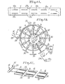
- FIG. 3C shows an elastic strip supply roller 28 which is feeding two continuous strips 16', 18' of elastic material onto transfer members comprising a platen 30 on which are mounted a pair of flexible strip supports 32.
- flexible strip supports 32 may be selectively manipulated to change their configuration from, for example, the linear configuration shown at station A of iigure 3C to the curvilinear configuration shown at station of Figure 3C.
- Stations A, B, and C of Figure 3C show, espectively, sequential stages in the operation which are also indicated at, respectively, stations A, B, and C of Figure 3B.
- FIG. 3B shows a schematic version of apparatus in accordance with one embodiment of the invention, in which a plurality of transfer means 30 are mounted on a rotatable support means generally indicated at 34 and comprising a cylindrical or wheel-like carriage means 36 mounted for rotation upon a rotatable shaft 38 by a plurality of spoke members 40 emanating from a hub portion (unnumbered) mounted to rotate with shaft 38.
- 3poke members 40 support an annular shaped web portion 41 which supports carriage portion 42 which provides a wide, drum-like structure, axially opposite ends of which may be received within a plurality of guide rollers 44.
- the opposite ends of shaft 38 and the guide rollers 44 are mounted on a pair of opposed vertical wall stanchions 46, 46a, the latter being broken away for clarity of illustration.
- Guide rollers 44 are mounted on the broken-away portion of wall stanchion 46a and corresponding guide rollers, not visible in Figure 3B, are mounted on wall stanchion 46, to supportingly engage the opposite periphery of carriage portion 42.
- Each transfer member 30 is mounted upon a respective support 48 carried by carriage portion 42 and a respective bearing member 50 affixed to web portion 41 of carriage means 36.
- rotatable support means 34 rotates in the direction indicated by the circular arrow D whereby transfer members 30 are carried in a closed, orbital path passing through a supply zone S and a transfer zone T in each rotation cycle.
- elastic strip supply roller 28 feeds a pair of elastic strips 16', 18' to a transfer member 30 in the supply zone S comprising the indicated portion of the orbital path defined by transfer members 30; as rotatable support means 34 rotates in the direction : indicated.
- a pressure roller 52 (shown in Figure 3B but not in Figure 3C) presses the elastic strips 16', 18' to adhere them to flexible strip supports 32 and a rotating cutter means 54 cuts the continuous strips 16', 18' to discrete strips 16, 18 adhered to respective flexible strip supports 32.
- the discrete strips 16, 18 may be adhered to flexible strips supports 32 by any suitable means.
- One preferred method is to utilize as the elastic strip material a self-adhering elastic material such as that sold under the trademark FULLASTIC by H.B.
- the flexible strip supports 32 are made of a compatible material to which the self-adhering elastic strip material will adhere sufficiently for purposes of the invention and from which the elastic strips can be removed for transfer to web of material as described below.
- suitable methods may be employed to temporarily adhere the elastic strips to the flexible strip supports.
- vacuum may be supplied to openings on the top surface of flexible strip supports 32 to hold the elastic strips in place, or mechanical clamping means may be utilized.
- pressure roller 52 serves to firmly but temporarily adhere elastic strips 16', 18' to flexible.strip supports 32.
- flexible strip support means 32 is changed to its final curvilinear configuration shown at station C of Figure 3C (the location of station C is shown in Figure 3C).
- the travel time after leaving cutter 54 and prior to arriving at station C is sufficient to impart any desired configuration to flexible strip supports 32 and thereby to the discrete elastic strips 16, 18. adhered thereto.
- transfer member 30 is about to enter transfer zone T in which the discrete elastic strips 16, 18 are transferred to a continuous web 24a of second material which is transported by means of transport rollers 56a, 56b and 56c and transfer roller 58 in the direction indicated by the arrow associated with web 24a in Figure 3B.
- the adhesion strength of discrete strip 16, 18 on flexible strip supports 32 is considerably less than the adhesive attraction between discrete strip 16, 18 and web 24a so that the discrete strips are removed from flexible strip supports 32 and transferred to web of second material 24a in the transfer zone T.
- an adhesive may be employed to secure strips 16, 18 to a web 24a and this adhesive may be applied to the strips 16, 18 while they are supported on the flexible strip supports 32, or adhesive may be applied to web 24a in a desired pattern, or both. Any other means, e.g., ultrasonic welding, may be employed to securely attach the strips to a web 24a.
- the diameter of transfer roller 58 is sized so that continuous web 24a is separated from transfer member 30 at an angle (angle a in Figure 3A) large enough to insure removal of the discrete strips 16, 18 from strip supports 32.
- Angle.1- is the angle formed between the support surface of strip supports 32 and a tangent to the outer diameter of transfer roller 58 at the point where it presses web 24a into contact with strip supports 32 of transfer members 30. This angle must be large enough so that the adhesive force between the flexible strip supports and the discrete strips of first material is overcome by the adhesive force between web 24a and the discrete strips.
- the configuration of flexible strip supports 32 is returned by the configuration-changing means (not shown in Figure 3B) to a straight or linear configuration so that upon entering supply zone S continuous elastic strips 16', 18' may be fed thereto to repeat the cycle.
- the resultant product is shown in plan view in Figure 3A comprising the continuous web 24a of second material having thereon a plurality of curvilinear elastic strips 16a, 18a which have a'sharp curvature as indicated in Figure 3A. It will be appreciated that the method and means described to impart the curvilinear configuration to strips 16a, 16b are not limited by the linear speed of movement of web 24a.
- supply roller 28 and pressure roller 52 together with cutter 54 comprise one embodiment of supply means for supplying one or more discrete strips of first material to the transfer means.
- transport rollers 56a, 56b and 56c, together with transfer roller 58 comprise one embodiment of web transport means.
- absorbent material and a top sheet may be applied to web 24a, and the resulting composite cut transversely at the places indicated by the dashed lines r in Figure 3A to provide individual disposable diapers or other garments in which the curvilinear elastic strips 16a, 18a are utilized as the leg elastics to provide a snug, contour fitted leg opening in the garment.
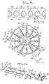
- Figures 4A, 4B and 4C generally correspond to, respectively, Figures 3A, 3B and 3C. Parts in Figure 4B (and in Figure 5B) which correspond to parts in Figure 3B are identically numbered and other parts in Figures 4B and 5B have been omitted or broken away for improved clarity of illustration.
- Figures 4A, 4B and 4C illustrate an embodiment of the invention wherein supports 48 of transfer members 30 are radially translatable, i.e., are movable radially inwardly and outwardly in their respective bearing members 50, so that the effective orbital radius of individual transfer members 30 may be selectively adjusted to different radii at different zones of a single rotation cycle.
- supports 48 may comprise splined shafts mounted in bearing members 50 and, optionally, additional collar bearings (not shown in Figure 4B) may be provided in carriage portion 42 to further support the splined shafts comprising support 48.
- An additional feature of the apparatus shown in Figure 4B comprises a closed cam path 60 which may be mounted on wall stanchion 46 (not shown in Figure 4B) and within which are received rollers comprising cam followers 62 fitted to the radially inner ends of supports 48.
- Cam 60 may comprise a track on one or both of wall stanchions 46, 46a (not shown in Figure 4B) or may be provided on a cylindrical, barrel-like structure (of the type illustrated in Figures 6 and 7) which is mounted on one or the other of the wall stanchions.
- cam 60 defines an eccentric path relative to the center of rotation defined by the rotational axis of rotatable shaft 38 so that the orbital radius of a transfer member 30 in supply zone S is less than the orbital radius of a transfer member 30 in transfer zone T. Since the angular velocity of each transfer member 30 is constant, the linear velocity of the transfer members 30 in transfer zone T is greater than the linear velocity of transfer members in supply zone S.
- the orbital radius and consequently the linear velocity of transfer members in the supply zone may be made greater (or lesser) than those in the transfer zone and a selected orbital radius and concomitant linear velocity may be selected along any segment of the closed orbital path of the transfer members 30.
- This flexibility can provide very significant advantages.
- the length of an individual discrete strip 16a or 18a may be made greater or less than the length of the repeat (the distance in the direction of web travel between dashed lines r) of the web 24a of second material.
- the apparatus illustrated in Figure 5B is similar or may be identical to that shown in Figures 3B and 4B, but is capable not only of changing the configuration of the flexible strip supports and the orbital radius of the transfer members but also of selectively radially pivoting supports 48 about their longitudinal axes. This pivoting changes the orientation of transfer members 30, and thereby of flexible strip supports 32, between the supply zone S and the transfer zone T.
- cam 60 is seen to provide a larger orbital radius and therefore a higher linear velocity to transfer members in supply zone S than in transfer zone T. This permits the application to each transfer member 30 of a length of elastic strip 16', 18' longer than the repeat of web 24a.
- means are also provided to enable radially pivoting supports 48 (and transfer member 30) about their respective longitudinal axes a selected amount, e.g., 90 degrees, to change the orientation of the discrete strips 16, 18 of first material relative to web 24a.
- the apparatus of Figure 5B includes a cam track 60 and cam followers 62, and has supports 48 mounted in bearings 50 for radial translation relative to rotatable shaft 38 and pivoting movement about their own longitudinal axes.
- transfer members 30 In operation, as transfer members 30 pass through supply zone S, cam followers 62 following cam 60 thrust supports 48 radially outwardly thereby imposing upon them an orbital velocity greater than their orbital velocity in transfer zone T and moving them concurrently with elastic strips 16', 18' supplied by supply roller 28 and pressed into adhering contact with flexible strip supports 32 by pressure roller 52.
- cutter 54 After leaving supply zone S cutter 54 cuts elastic strips 16', 18' into discrete strip 16a, 18a. After leaving the area of cutter 54 a pivoting motion about their longitudinal axis is imposed upon supports 48 by means not shown in Figure 5B but equivalent to those described in detail with respect to Figures 6 and 7.
- Transfer members 30 are correspondingly pivoted as indicated by the rotational arrows and axis lines shown in Figure 5B in the vicinity of station C.
- any one or more of the three features of (a) changing the configuration of the flexible strip supports and thereby of the discrete elastic strips adhered thereto, (b) changing the orbital radius of the transfer members in the different zones of the closed orbital path through which the transfer members move and (c) changing the orientation of transfer members 30 between the supply zone S and the transfer zone T, may be employed individually or in any bombination.
- the elastic strips may be supplied at a linear speed independent of the linear speed of the web of material to which the strips are to be applied, so that a length of elastic strips greater than, equal to or less' than the repeat length of the web maybe utilized, and configurations including sharply curvilinear configurations may be imposed on the elastic strips independently of the web travel speed.
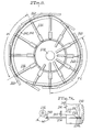
- Transfer means 100 comprises a rotatable shaft 102 mounted for rotation in a pair of opposed wall stanchions 104, 106 and on which a rotatable support means generally indicated at 108 is mounted for rotation with shaft 102.
- Rotatable support means 108 comprises a spider hub portion 110 having a plurality of shaft bearings 112 mounted thereon to receive supports (shafts) 114 of transfer members 116.
- Carriage means 118 comprises, in this embodiment, a cylindrical carriage frame 120 having annular peripheral edge collars 122, 124 extending along opposite edges thereof and reinforced at intervals by flanges 126.
- a plurality of roller cam followers 128 are mounted at spaced apart locations along, respectively, annular peripheral collars 122 and 124 and are engaged within a track provided by cam tracks 130, 132 mounted on respective facing walls of wall stanchions 104, 106.
- cam tracks 130, 132 are circular in plan view, the device illustrated in Figure 6 being one designed to operate with a constant orbital radius of the transfer members 116.
- individual carriage frames for each transfer member 116 are provided, as in the Figure 7 embodiment.
- a barrel cam 134 is mounted on the interior facing wall of wall stanchion 104 concentrically with cam tracks 130, 132 and has a spiral cam track 136 extending annularly around the periphery of barrel cam 134.
- Connecting shafts 138 are connected eccentrically to pivot links 140 which are in turn connected to supports 114 so that pivoting of pivot links 140 will pivot supports 114 about their respective longitudinal axes.
- the opposite ends of connecting shafts 138 are connected to roller cam followers 142 which engage spiral cam track 136 of barrel cam 134.
- a plurality of collar bearings 144 receive respective support shafts 114 pivotably within cylindrical carriage frame 120.
- spiral cam track 136 forces roller cam followers 142 rightwardly as viewed in the drawings so that by the time a transfer member 146 reaches the position at the top of Figure 6, cam follower 142 is in its rightward most position and pivot link 140 associated therewith has been moved rightwardly to complete a 90° pivoting of support 114 about its own longitudinal axis in its bearing 112. At this juncture the side edge 116b of transfer member 116 (at the top of the drawing) is visible head-on as is the side edge of one of support strips 146, which are now oriented transversely to the direction of orbiting of transfer member 116.
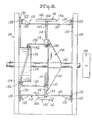
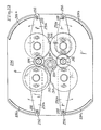
- FIG 7 there is shown another embodiment of the invention which provides not only for pivoting of the transfer members about their supports to selectively change orientation of the transfer members, but for selectively changing the orbital radius of the transfer members and the configuration of the flexible strip supports.
- Figure 7 shows only a portion of the transfer means and omits the supply means and web transport means which would be associated therewith. Only one of a plurality of transfer members and associated carriage frames is shown.
- the transfer means of the embodiment of Figure 7 is generally indicated at 200 and comprises a rotatable shaft 202 mounted, like the embodiment of Figure 6,- between a pair of opposed wall stanchions which, however, are not shown in Figure 7.
- Rotatable support means indicated generally at 204 comprise in the illustrated embodiment a plurality of radial support arms 206, 208, secured by means of arm mounting members 210, 212 which are affixed to rotatable shaft 202 for rotation therewith.
- radial support arms 206, 208 are provided in pairs which are longitudinally aligned on shaft 202 and each radial arm has a respective radially extending track 214, 216 thereon, tracks 214 and 216 being parallel to each other and lying in the same plane passing through the longitudinal axis of rotation of shaft 202.
- a bearing support element 218 has shaft bearings 220, 222 mounted thereon and is itself mounted for rotation with shaft 202 by bearing mounting means 224.
- support 226 comprises a splined shaft rotatably mounted within shaft bearings 220, 222 and extending through a roller bearing collar 228 which is mounted on carriage frame 230.
- Each carriage frame 230 is mounted by means of its associated carriage trolleys 232, 234 which are respectively mounted on radially extending tracks 214, 216 for sliding movement thereon.
- End plates 236, 238 are formed respectively at the opposite side ends of carriage frame 230 and carry respective sets of roller cam followers 240 mounted thereon.
- Reinforcing flanges may be used to help secure annular peripheral collars 238, 234 through carriage frame 230 in the same manner as indicated in the embodiment of Figure 6.
- Each transfer member is mounted in the manner described on its associated carriage means and shaft bearings.
- Cam tracks 242, 244 are mounted on the facing interior wall of the wall stanchions (not shown) and roller cam followers 240 are engaged therewith so that upon rotation of transfer means 204 the cam followers and consequently each carriage frame 230 is compelled to follow the track of cam tracks 242, 244.
- cam tracks 242 and 244 are closed tracks eccentric in plan view and the mirror image of each other.
- barrel cam 246 comprising a cylindrical barrel 248 having a spiral cam track 250 extending about the exterior periphery thereof in a manner similar to that illustrated in the Figure 6 embodiment.
- a connecting shaft 252 ( Figures 7 and 7A) is connected at the tracking end thereof to a roller cam follower assembly 254 comprising, as best seen in Figure 7, a pair of rollers 254a engaging respectively opposite sides of spiral cam track 250.
- a connector link 256 has one end mounted on cam follower assembly 254 and is pivotably connected to the tracking end of connecting shaft 252.
- connector link 256 is pivotably mounted on pivot link support arm 257 which is secured by supporting flange 259 to radial support arm 208.
- the distal or free end of connecting shaft 252 is connected to pivot collar 258 which is non-rotatably mounted on support 226 in the splined shaft portion thereof.
- Support 226 is, however, slideable longitudinally in pivot collar 258.
- Transfer member 260 is affixed non-rotatably to the radially outward end of support 226 by locking collar 2G2.
- Rotatable shaft 202 is shown in its relative position to the transfer members and the track of cam tracks 242, 244 is indicated.
- parts such as those corresponding to carriage frame 230, shaft bearings 222, radial support arms 206, 208, etc. are omitted from the schematic diagram of Figure 8.
- carriage frame 230 rotates along the course on which it is constrained by cam tracks 242, 244 it describes eccentric rotation relative to shaft 202, which eccentric motion is accommodated by the radially translating travel of carriage trolleys 232, 234 along tracks 214, 216 of respective radial arms 206, 208 ( Figure 7).
- transfer members 260 when traveling through zone Z-l of their closed orbital path are at their radially outermost position and while traveling through zone Z-2 are at their radially innermost position. Since the angular speed -of rotation is determined by the speed of rotation of rotatable shaft 202, individual transfer members 260 have a uniform angular speed and their linear speed along their orbital path varies directly with their effective orbital radius, i.e., the radius distance between transfer members 260 and the longitudinal axis of rotation of shaft 202.
- spiral cam 250 ( Figures 7 and 7A) will act on connecting shaft 252 to provide a desired degree of pivoting of transfer members 260 as they travel along their closed orbital path of travel to change the orientation thereof. This occurs by roller cam follower assembly 254 following spiral cam track 250 and pivoting pivot collar 258 90° to the position shown in dotted lines in Figure 7A. Pivoting of the transfer members may be selected to change their orientation, and that of the strips of first material carried thereon, any desired amount.
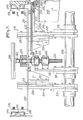
- Figure 9 shows a plan view of a transfer member 260 which, as best seen in Figures 10 and 11, has a generally beveled upper surface 264 on which are formed a pair of raised lands 266, 266a having respective curvilinear anvil surfaces 270, 270a.
- anvil surfaces 270, 270a are slightly undershot, that is, the anvil surfaces 270, 270a are disposed at a slight angle to the vertical with the upper portion thereof projecting in a slight overhang.
- a pair of flexible strip supports 272, 274 are mounted on upper surface 264 and are shown in Figure 9 in their linear configuration.
- flexible strip supports 272, 274 are generally trapezoidal shaped in cross section so as to matingly engage the slightly undershot respective anvil surfaces 270, 270a.
- a central raised land portion 278 is substantially rectangular in projected configuration as seen in Figure 9 and provides a pair of opposed stop surfaces 280, 282.
- curvilinear slots 284a, 284b and 286a, 286b are formed along the outer periphery of upper surfaces 264.
- mounting pins 288 Figures 10 and 11
- Mounting pins 288 have enlarged heads at one end which are embedded within respective opposite ends of flexible strip supports 272, 274.
- Locking nuts 292 secure mounting pins 288 to respective ones of pivot arms 290a-d.
- the central body portion of mounting pins 288 extend through respective ones of slots 284a, 284b, 286a and 286b.
- flexible strip supports 272, 274 are moved from their linear configuration aligned with and held against stop surfaces 280, 282 respectively to a curvilinear configuration conforming to respective ones of anvil surfaces 270, 270a.
- the latter curvilinear configuration is shown in dot-dash outline in Figure 9.
- Flexible strip supports 272, 274 may be made of any suitable material such as a synthetic organic polymeric material having flexible or elastomeric properties.
- At least the top surface of supports 272, 274 are preferably made of a material to which self-adhering elastic strips will adhere with sufficient strength so that upon changing the configuration of the flexible support 272, 274 from the linear configuration shown in solid line in Figure 9 to the curvilinear configuration shown in dot-dash outline in Figure 9, the discrete elastic or other strips adhered thereto will have their configuration similarly changed.
- FIG. 12 the under surface 294 of transfer member 260 is seen in Figure 12 and has secured thereto a mounting collar generally indicated at 296 which is secured to transfer member 260 by a bolt-like fastening means (not shown) inserted through stepped mounting opening 298 as best seen in Figures 9 and 11.
- Mounting collar 296 is configured and dimensioned to be received over the upper (as viewed in Figure 7) end of support shaft 226 and to engage roller bearing collar 228 mounted on carriage frame 230.
- a drive gear 300 is non-rotatably affixed to mounting collar 296 so that upon pivoting of support shaft 226 drive gear 300 drives secondary gears 302, 304 which in turn drive spur gears 306, 308, 310 and 312.
- pivot arms 290a, 290b, 290c and 290d are respectively pivoted in the direction of the arrows associated therewith in Figure 12, with the result that flexible strips 272, 274 are moved into conformity with respectively, anvil surfaces 270 and 270a thereby changing their configuration from a linear configuration to a sharply curved curvilinear configuration.
- the pivoting of support shaft 226 is coordinated with the changing of the configuration of flexible support strips 272, 274 so that the desired degree of transfer member pivoting, 90° in this case, is attained together with the full conformance of flexible support strips 272, 274 with anvil surfaces 270, 270a.
- the strips of first material comprise strips of an elastic material and may be of any suitable configuration such as ribbons or cord-like strands.
- such strips of first material may also comprise materials which are activatable from a substantially non-elastic to an elastic state at least sufficient, for example, to adequately close and seal the leg openings of a disposable diaper or other incontinence control garment.
- activatable elastic materials include those which are activated by heat so that the strips of first material are applied in an untensioned, substantially non-elastic state to the web of second material and thereafter heated to elasticize the material.
- heat activated materials are known, (e.g., U.S.
- the strip of first material may comprise a moisture activatable material, that is, a material which is converted from a substantially non-elastic to an elastic condition by contact with moisture, such as urine.
- Flexible strip supports 272, 274 are preferably made of a material to which a self-adhering elastic strip material (of the type discussed above with respect to U.S. Patents 4,259,220 and 4,418,123) readily adheres.
- flexible strip supports 272 and 274 may be made of a silicone rubber such as that supplied by American Roller Company of Union Grove, Wisconsin under product number 12-952.15-1531.
- a material such as an EPDM "artificial natural rubber" may be utilized -29- for flexible strip supports.
- flexible strip support 272 has embedded in the top surface thereof a pair of longitudinally spaced-apart transverse interrupter strips 314a, 314b.
- the interrupter strips are made of a material, such as brass or a urethane rubber, to which the self-adhering elastic strip will adhere with significant strength.
- Transverse interrupter strips 314a, 314b are respectively positioned inwardly from opposite ends 272a and 272b of strip support 272 sufficiently to provide a cutting area between each interrupter strip and its respective adjacent end. It is in this cutting area that strip is cut into discrete pieces as by the cutter 54 illustrated in Figures 3A - 5A.
- Flexible strip support 274 is identically provided with transverse interrupter strips 316a, 316b.
- the interrupter strips 314a, b and 316a, b interrupt the release action, thereby helping to insure that the portion of the self-adherent elastic strip contacting the flexible strip support between the respective pairs of interrupter strips remains adhered to the flexible strip support until transferred.
Landscapes
- Health & Medical Sciences (AREA)
- Engineering & Computer Science (AREA)
- Vascular Medicine (AREA)
- Epidemiology (AREA)
- Biomedical Technology (AREA)
- Heart & Thoracic Surgery (AREA)
- Life Sciences & Earth Sciences (AREA)
- Animal Behavior & Ethology (AREA)
- General Health & Medical Sciences (AREA)
- Public Health (AREA)
- Veterinary Medicine (AREA)
- Manufacturing & Machinery (AREA)
- Absorbent Articles And Supports Therefor (AREA)
- Advancing Webs (AREA)
- Folding Of Thin Sheet-Like Materials, Special Discharging Devices, And Others (AREA)
Applications Claiming Priority (2)
| Application Number | Priority Date | Filing Date | Title |
|---|---|---|---|
| US06/673,064 US4578133A (en) | 1984-11-19 | 1984-11-19 | Method and apparatus for applying discrete strips to a web of material |
| US673064 | 1984-11-19 |
Publications (1)
| Publication Number | Publication Date |
|---|---|
| EP0184072A1 true EP0184072A1 (fr) | 1986-06-11 |
Family
ID=24701176
Family Applications (1)
| Application Number | Title | Priority Date | Filing Date |
|---|---|---|---|
| EP85114745A Withdrawn EP0184072A1 (fr) | 1984-11-19 | 1985-11-19 | Procédé et dispositif pour appliquer des morceaux de ruban à une feuille de matériau |
Country Status (8)
| Country | Link |
|---|---|
| US (1) | US4578133A (fr) |
| EP (1) | EP0184072A1 (fr) |
| JP (1) | JPS61162462A (fr) |
| KR (1) | KR860003801A (fr) |
| AU (1) | AU4995885A (fr) |
| BR (1) | BR8505800A (fr) |
| GB (1) | GB2170482A (fr) |
| ZA (1) | ZA858723B (fr) |
Cited By (7)
| Publication number | Priority date | Publication date | Assignee | Title |
|---|---|---|---|---|
| EP0286635A4 (fr) * | 1985-10-28 | 1989-02-16 | Kimberly Clark Co | Procede et appareil pour appliquer a un substrat un materiau elastique de forme anatomique. |
| EP0304044A1 (fr) * | 1987-08-18 | 1989-02-22 | Uni-Charm Corporation | Dispositif pour appliquer une bande élastique sur une feuille en mouvement |
| EP0251251A3 (en) * | 1986-06-30 | 1989-03-22 | Toyo Eizai Kabushiki Kaisha | Elasticized unit, apparatus for making the elasticized unit, garments incorporating the units, and method for making the garment |
| GB2234157A (en) * | 1989-06-29 | 1991-01-30 | Uni Charm Corp | Method for manufacturing disposable underpants |
| US6340782B1 (en) | 1989-10-04 | 2002-01-22 | Sca Hygiene Products Aktiebolag | Method of securing an elastic band and an article that includes such an elastic band |
| CN107709202A (zh) * | 2015-07-02 | 2018-02-16 | 新兴机械株式会社 | 运送装置 |
| EP4678575A1 (fr) * | 2024-07-10 | 2026-01-14 | Grob-Werke GmbH & Co. KG | Dispositif, unité de transport et procédé de transport d'éléments souples |
Families Citing this family (105)
| Publication number | Priority date | Publication date | Assignee | Title |
|---|---|---|---|---|
| US4556596A (en) * | 1984-11-30 | 1985-12-03 | Kimberly-Clark Corporation | Method for adhering tensioned elastic strips to a flexible base material and article produced therefrom |
| DE3444331A1 (de) * | 1984-12-05 | 1986-06-05 | Winkler & Dünnebier, Maschinenfabrik und Eisengießerei GmbH & Co KG, 5450 Neuwied | Verfahren und vorrichtung zum aufbringen elastischer baender auf eine werkstoffbahn |
| US4726876A (en) * | 1985-10-18 | 1988-02-23 | Kimberly-Clark Corporation | Apparatus for repositioning discrete articles |
| US4767487A (en) * | 1985-10-18 | 1988-08-30 | Kimberly-Clark Corporation | Method for repositioning discrete articles |
| US4813946A (en) * | 1985-10-24 | 1989-03-21 | Sabee Reinhardt N | Method and apparatus for forming and transporting elastic ribbons |
| US4648928A (en) * | 1986-02-27 | 1987-03-10 | Kimberly-Clark Corporation | Method and apparatus for applying discrete strips of material to a longitudinally extending web |
| US4908247A (en) * | 1986-04-15 | 1990-03-13 | The Procter & Gamble Company | Article including segment which is elastically shirrable after manufacture |
| US4968313A (en) * | 1987-04-27 | 1990-11-06 | Sabee Reinhardt N | Diaper with waist band elastic |
| US4834741A (en) * | 1987-04-27 | 1989-05-30 | Tuff Spun Products, Inc. | Diaper with waist band elastic |
| JPH0780609B2 (ja) * | 1987-06-29 | 1995-08-30 | ユニ・チャ−ム株式会社 | 移動ウェブへの弾性バンド貼着装置 |
| JPH0761349B2 (ja) * | 1987-07-03 | 1995-07-05 | ユニ・チャ−ム株式会社 | 移動ウエブへの弾性バンド貼着方法および装置 |
| JPH0780610B2 (ja) * | 1987-08-04 | 1995-08-30 | 株式会社瑞光 | 使捨ておむつの製造方法 |
| JPH0780611B2 (ja) * | 1987-10-09 | 1995-08-30 | 大正製薬株式会社 | 粘着フィルムに対するパッドの連続貼付方法及びその装置 |
| JPH0777946B2 (ja) * | 1987-10-09 | 1995-08-23 | 大正製薬株式会社 | 粘着フィルムに対するパッドの連続貼付方法及びその装置 |
| US5591298A (en) * | 1988-01-19 | 1997-01-07 | Kimberly-Clark Corporation | Machine for ultrasonic bonding |
| US5092862A (en) * | 1988-03-23 | 1992-03-03 | The Procter & Gamble Company | Elastic securement of an article with segments capable of being elastically shirred |
| US4995928A (en) * | 1988-10-31 | 1991-02-26 | Sabee Reinhardt N | Method and apparatus for forming and transporting elastic ribbons |
| US5167897A (en) * | 1991-02-28 | 1992-12-01 | The Procter & Gamble Company | Method for incrementally stretching a zero strain stretch laminate web to impart elasticity thereto |
| US5156793A (en) * | 1991-02-28 | 1992-10-20 | The Procter & Gamble Company | Method for incrementally stretching zero strain stretch laminate web in a non-uniform manner to impart a varying degree of elasticity thereto |
| US5143679A (en) * | 1991-02-28 | 1992-09-01 | The Procter & Gamble Company | Method for sequentially stretching zero strain stretch laminate web to impart elasticity thereto without rupturing the web |
| SE501940C2 (sv) * | 1992-09-15 | 1995-06-26 | Moelnlycke Ab | Förfarande och anordning för att anbringa elastiska element på en långsträckt löpande materialbana |
| US5396978A (en) * | 1993-08-09 | 1995-03-14 | The Procter & Gamble Company | Apparatus for attaching elastic at an angle |
| US5716478A (en) * | 1995-10-17 | 1998-02-10 | Kimberly-Clark Worldwide, Inc. | Apparatus and method for applying discrete parts onto a moving web |
| US5660665A (en) * | 1995-12-15 | 1997-08-26 | Kimberly-Clark Corporation | Rotating transfer roll with rotating extensible platen |
| US6254714B1 (en) * | 1997-07-29 | 2001-07-03 | William P. Niedermeyer | Method and apparatus for undergarment assembly |
| US6165306A (en) | 1998-06-01 | 2000-12-26 | Kimberly-Clark Worldwide, Inc. | Process and apparatus for cutting of discrete components of a multi-component workpiece and depositing them with registration on a moving web of material |
| EP0974323A1 (fr) * | 1998-07-22 | 2000-01-26 | The Procter & Gamble Company | Appareil pour transporter et manipuler une bande continue |
| US6620276B1 (en) * | 1998-07-22 | 2003-09-16 | The Procter & Gamble Company | Apparatus for transporting a continuous web, and for manipulating the web |
| EP1004285A1 (fr) * | 1998-11-23 | 2000-05-31 | The Procter & Gamble Company | Procédé pour appliquer des portions discrètes de bande sur une bande de réception |
| US6074333A (en) * | 1998-12-24 | 2000-06-13 | Kimberly-Clark Worldwide, Inc. | Machine for cutting discrete components of a multi-component workpiece and depositing them with registration on a moving web of material |
| US6059710A (en) * | 1998-12-24 | 2000-05-09 | Kimberly-Clark Worldwide, Inc. | Process for cutting of discrete components of a multi-component workpiece and depositing them with registration on a moving web of material |
| EP1020169A1 (fr) * | 1999-01-16 | 2000-07-19 | The Procter & Gamble Company | Procédé et dispositif pour enduire des portions isolées d'une bande sur une bande de réception |
| US6656312B1 (en) | 1999-01-16 | 2003-12-02 | The Procter & Gamble Company | Apparatus and process for applying discrete portions of a web material onto receiving web |
| US6250357B1 (en) * | 1999-03-15 | 2001-06-26 | William P. Niedermeyer | Method and apparatus for briefs with pad support panel |
| US6617490B1 (en) | 1999-10-14 | 2003-09-09 | Kimberly-Clark Worldwide, Inc. | Absorbent articles with molded cellulosic webs |
| US6692603B1 (en) | 1999-10-14 | 2004-02-17 | Kimberly-Clark Worldwide, Inc. | Method of making molded cellulosic webs for use in absorbent articles |
| US6375769B1 (en) | 2000-08-15 | 2002-04-23 | Kimberly-Clark Worldwide, Inc. | Method of applying curved leg elastics using pucks with curved surfaces |
| US6569275B1 (en) | 2000-08-15 | 2003-05-27 | Kimberly-Clark Worldwide, Inc. | Method of optimizing tension in applying leg elastics |
| US6540857B1 (en) | 2000-08-15 | 2003-04-01 | Kimberly-Clark Worldwide, Inc. | Method of applying curved leg elastics using curved pucks |
| US6585841B1 (en) | 2000-08-15 | 2003-07-01 | Kimberly-Clark Worldwide, Inc. | Method of optimizing spacing between elastic members in applying leg elastics |
| US6440246B1 (en) | 2000-08-15 | 2002-08-27 | Kimberly-Clark Worldwide, Inc. | Method of applying curved leg elastics using rotating disks |
| US6613033B1 (en) | 2000-08-15 | 2003-09-02 | Kimberly-Clark Worldwide, Inc. | Pant-like absorbent garments having curved leg cuffs |
| US6652504B1 (en) | 2000-08-15 | 2003-11-25 | Kimberly-Clark Worldwide, Inc. | Pant-like absorbent garments having curved leak guard flaps |
| US6689115B1 (en) | 2000-08-15 | 2004-02-10 | Kimberly-Clark Worldwide, Inc. | Absorbent garment with asymmetrical leg elastic spacing |
| US6635041B1 (en) | 2000-08-15 | 2003-10-21 | Kimberly-Clark Worldwide, Inc. | Absorbent garment with asymmetrical leg elastic tension |
| JP3798298B2 (ja) * | 2000-12-01 | 2006-07-19 | 株式会社瑞光 | 回転装置、着用物品の搬送方法およびウェブの搬送方法 |
| GB2370490A (en) * | 2000-12-12 | 2002-07-03 | Rectella Internat Ltd | Absorbent garment |
| ITBO20010360A1 (it) * | 2001-06-06 | 2002-12-06 | Gd Spa | Unita' per l'applicazione di tagliandi a pacchetti in macchine confezionatrici |
| EP1297807A1 (fr) * | 2001-10-01 | 2003-04-02 | The Procter & Gamble Company | Article absorbant avec joint d'étanchéité des bords et son procédé de fabrication |
| US6820671B2 (en) * | 2001-10-05 | 2004-11-23 | Paragon Trade Brands, Inc. | Apparatus and method for assembling absorbent garments |
| US7341087B2 (en) * | 2002-01-02 | 2008-03-11 | Kimberly-Clark Worldwide, Inc. | Apparatus for applying discrete parts to a moving web |
| US7008497B2 (en) * | 2002-08-22 | 2006-03-07 | Zuiko Corporation | Method and apparatus for producing wearing article |
| JP4012042B2 (ja) * | 2002-11-01 | 2007-11-21 | 株式会社瑞光 | 着用物品の製造装置 |
| US6942086B2 (en) | 2002-11-22 | 2005-09-13 | The Procter & Gamble Company | Transfer apparatus for transferring a workpiece from a moving anvil to a moving carrier |
| US6848566B2 (en) * | 2003-06-30 | 2005-02-01 | The Procter & Gamble Company | Continuously adjustable apparatus for repositioning discrete articles |
| WO2005005296A1 (fr) * | 2003-07-11 | 2005-01-20 | Zuiko Corporation | Dispositif de transmission et dispositif de traitement |
| US7179343B2 (en) * | 2003-12-19 | 2007-02-20 | Kimberly-Clark Worldwide, Inc. | Method for bonding surfaces on a web |
| DE10361856A1 (de) * | 2003-12-30 | 2005-07-28 | Paul Hartmann Ag | Verfahren und Vorrichtung zum Applizieren eines Flachmaterialbahnabschnitts |
| JP4778684B2 (ja) * | 2004-01-30 | 2011-09-21 | 株式会社島精機製作所 | 裁断機の吸引調整方法および装置 |
| JP4745061B2 (ja) * | 2004-02-05 | 2011-08-10 | 株式会社瑞光 | ウエブの加工装置 |
| US20060059598A1 (en) * | 2004-06-30 | 2006-03-23 | Kimberly-Clark Worldwide, Inc. | Method of forming leg cuffs for wearable articles and articles made thereby |
| CN101056604B (zh) * | 2004-11-12 | 2013-02-13 | 宝洁公司 | 能够适形下面的形状的处理制品 |
| US7975584B2 (en) | 2007-02-21 | 2011-07-12 | Curt G. Joa, Inc. | Single transfer insert placement method and apparatus |
| US9944487B2 (en) | 2007-02-21 | 2018-04-17 | Curt G. Joa, Inc. | Single transfer insert placement method and apparatus |
| US9550306B2 (en) | 2007-02-21 | 2017-01-24 | Curt G. Joa, Inc. | Single transfer insert placement and apparatus with cross-direction insert placement control |
| RU2430710C1 (ru) * | 2007-07-05 | 2011-10-10 | Ска Хайджин Продактс Аб | Способ изготовления поглощающих изделий, содержащих эластичные элементы |
| EP2173301A4 (fr) * | 2007-07-05 | 2012-12-26 | Sca Hygiene Prod Ab | Procédé de fabrication d'articles absorbants contenant des élastiques |
| US20090294044A1 (en) * | 2008-05-27 | 2009-12-03 | Nathan Alan Gill | Methods and Apparatus for Attaching Elastic Components to Absorbent Articles |
| IT1390737B1 (it) * | 2008-07-04 | 2011-09-23 | Gdm Spa | Macchina per la realizzazione di articoli assorbenti. |
| WO2010126415A1 (fr) | 2009-04-30 | 2010-11-04 | Sca Hygiene Products Ab | Procédé destiné à fournir une toile élastique |
| US8100253B2 (en) | 2009-06-30 | 2012-01-24 | The Procter & Gamble Company | Methods and apparatuses for transferring discrete articles between carriers |
| US8673098B2 (en) * | 2009-10-28 | 2014-03-18 | Curt G. Joa, Inc. | Method and apparatus for stretching segmented stretchable film and application of the segmented film to a moving web |
| US9089453B2 (en) | 2009-12-30 | 2015-07-28 | Curt G. Joa, Inc. | Method for producing absorbent article with stretch film side panel and application of intermittent discrete components of an absorbent article |
| JP5492628B2 (ja) * | 2010-03-26 | 2014-05-14 | ユニ・チャーム株式会社 | 受け渡し装置 |
| JP5291164B2 (ja) * | 2011-08-31 | 2013-09-18 | ユニ・チャーム株式会社 | 吸収性物品の製造装置 |
| PL2628472T3 (pl) | 2012-02-20 | 2016-07-29 | Joa Curt G Inc | Sposób tworzenia spojeń między oddzielnymi częściami składowymi produktów jednorazowego użytku |
| US8720666B2 (en) * | 2012-04-16 | 2014-05-13 | The Procter & Gamble Company | Apparatuses for transferring discrete articles |
| US8833542B2 (en) | 2012-04-16 | 2014-09-16 | The Procter & Gamble Company | Fluid systems and methods for transferring discrete articles |
| US8607959B2 (en) * | 2012-04-16 | 2013-12-17 | The Procter & Gamble Company | Rotational assemblies and methods for transferring discrete articles |
| US8820513B2 (en) | 2012-04-16 | 2014-09-02 | The Procter & Gamble Company | Methods for transferring discrete articles |
| US9908739B2 (en) | 2012-04-24 | 2018-03-06 | Curt G. Joa, Inc. | Apparatus and method for applying parallel flared elastics to disposable products and disposable products containing parallel flared elastics |
| US9597235B2 (en) | 2012-05-01 | 2017-03-21 | The Procter & Gamble Company | Methods and apparatuses for rejecting defective absorbent articles from a converting line |
| US9585797B2 (en) | 2012-05-01 | 2017-03-07 | The Procter & Gamble Company | Methods and apparatuses for transferring absorbent articles and rejecting defective absorbent articles |
| PL2659869T3 (pl) * | 2012-05-02 | 2018-01-31 | Joa Curt G Inc | Urządzenie do umieszczania wkładek w pojedynczym przemieszczeniu ze sterowaniem poprzecznego umieszczania wkładek |
| JP6092406B2 (ja) * | 2012-10-23 | 2017-03-08 | ザ プロクター アンド ギャンブル カンパニー | ウェブ上に別個の物品を取着する方法 |
| US9764905B2 (en) * | 2012-10-23 | 2017-09-19 | The Procter & Gamble Plaza | Method and apparatus for advancing an absorbent article |
| US9283683B2 (en) | 2013-07-24 | 2016-03-15 | Curt G. Joa, Inc. | Ventilated vacuum commutation structures |
| USD703248S1 (en) | 2013-08-23 | 2014-04-22 | Curt G. Joa, Inc. | Ventilated vacuum commutation structure |
| USD703711S1 (en) | 2013-08-23 | 2014-04-29 | Curt G. Joa, Inc. | Ventilated vacuum communication structure |
| USD703712S1 (en) | 2013-08-23 | 2014-04-29 | Curt G. Joa, Inc. | Ventilated vacuum commutation structure |
| USD704237S1 (en) | 2013-08-23 | 2014-05-06 | Curt G. Joa, Inc. | Ventilated vacuum commutation structure |
| USD703247S1 (en) | 2013-08-23 | 2014-04-22 | Curt G. Joa, Inc. | Ventilated vacuum commutation structure |
| US9463942B2 (en) | 2013-09-24 | 2016-10-11 | The Procter & Gamble Company | Apparatus for positioning an advancing web |
| US9289329B1 (en) | 2013-12-05 | 2016-03-22 | Curt G. Joa, Inc. | Method for producing pant type diapers |
| WO2015094568A1 (fr) | 2013-12-19 | 2015-06-25 | The Procter & Gamble Company | Procedes et appareils pour la fabrication d'articles absorbants presentant des ceintures profilees |
| US9533483B2 (en) | 2014-09-26 | 2017-01-03 | Kimberly-Clark Worldwide, Inc. | Apparatus for and method of shaping and applying a segment to a moving web |
| EP4053055B1 (fr) | 2015-01-26 | 2026-03-18 | Curt G. Joa, Inc. | Appareil pour tourner et placer des produits |
| JP5961715B1 (ja) * | 2015-02-19 | 2016-08-02 | ユニ・チャーム株式会社 | 吸収性物品に係る連続シートの複合体の製造方法、及び製造装置 |
| US9511951B1 (en) | 2015-06-23 | 2016-12-06 | The Procter & Gamble Company | Methods for transferring discrete articles |
| US9511952B1 (en) | 2015-06-23 | 2016-12-06 | The Procter & Gamble Company | Methods for transferring discrete articles |
| WO2017019544A1 (fr) | 2015-07-24 | 2017-02-02 | Curt G. Joa, Inc. | Appareil et procédés de commutation à vide |
| ITUB20160592A1 (it) * | 2016-02-09 | 2017-08-09 | Gdm Spa | Unità di alimentazione di ali laterali di un articolo assorbente igienico e metodo di cambio formato dell’unità di alimentazione. |
| US11737930B2 (en) | 2020-02-27 | 2023-08-29 | Curt G. Joa, Inc. | Configurable single transfer insert placement method and apparatus |
| JP7503462B2 (ja) * | 2020-09-16 | 2024-06-20 | パナソニックホールディングス株式会社 | シート材搬送装置 |
| WO2022075978A1 (fr) * | 2020-10-06 | 2022-04-14 | Kimberly-Clark Worldwide, Inc. | Appareil et procédé de façonnage et d'application d'un segment sur une bande en mouvement avec galets presseurs à déplacement latéral |
Citations (4)
| Publication number | Priority date | Publication date | Assignee | Title |
|---|---|---|---|---|
| US4293367A (en) * | 1980-05-16 | 1981-10-06 | Johnson & Johnson Baby Products Company | Apparatus for effecting securement of a transversely moved elastic ribbon to a moving web |
| US4297157A (en) * | 1980-06-23 | 1981-10-27 | Weyerhaeuser Company | Method for application of elastic to articles |
| EP0154068A1 (fr) * | 1984-03-05 | 1985-09-11 | H.B. Fuller Company | Procédé et dispositif pour transférer et appliquer un matériau |
| EP0159627A2 (fr) * | 1984-04-23 | 1985-10-30 | Kimberly-Clark Corporation | Tambour rotatif de transfert |
Family Cites Families (14)
| Publication number | Priority date | Publication date | Assignee | Title |
|---|---|---|---|---|
| US3524781A (en) * | 1966-03-02 | 1970-08-18 | American Can Co | Application of thin line adhesive to a sheet using a grooved roll as applicator |
| DE1258718B (de) * | 1966-11-02 | 1968-01-11 | Winkler Duennebier Kg Masch | Vorrichtung zum Aufbringen des Fensterwerkstoffs auf mehrere Fensteroeffnungen in bewegten Zuschnitten aus Papier od. dgl. |
| US3728191A (en) * | 1971-03-19 | 1973-04-17 | Kimberly Clark Co | Waistband tape application for disposable diapers |
| US3805486A (en) * | 1972-05-31 | 1974-04-23 | Mahaffy & Harder Eng Co | Packaging apparatus and techniques |
| NL7415181A (nl) * | 1972-11-13 | 1976-05-25 | Spherex Inc | Inrichting voor het vormen van ringen. |
| US4208363A (en) * | 1972-11-28 | 1980-06-17 | Izon Corporation | Method of making a plurality of adjacent light pipe elements |
| GB1451994A (en) * | 1973-07-20 | 1976-10-06 | Smithe Machine Co Inc F L | Method and apparatus for cutting and applying patches |
| US4021293A (en) * | 1975-11-07 | 1977-05-03 | Stackpole Machinery Company | High speed labeling machine |
| US4227952A (en) * | 1979-04-16 | 1980-10-14 | Sabee Products, Inc. | Method and apparatus for making diapers with elastic bands |
| US4352712A (en) * | 1979-11-01 | 1982-10-05 | Paul William A | Apparatus for applying gasket-forming material to workpieces |
| US4284454A (en) * | 1980-05-12 | 1981-08-18 | Joa Curt G | Method and apparatus for applying elastic bands transversely to a diaper line |
| CA1146129A (fr) * | 1980-08-22 | 1983-05-10 | Edmund Radzins | Machine a appliquer un ruban elastique aux couches |
| JPS58174603A (ja) * | 1982-04-07 | 1983-10-13 | ユニ・チヤ−ム株式会社 | 使い捨ておむつにおける弾性部材の取付装置 |
| JPS59217561A (ja) * | 1983-05-24 | 1984-12-07 | Toyo Seikan Kaisha Ltd | フイルム片の送出方法 |
-
1984
- 1984-11-19 US US06/673,064 patent/US4578133A/en not_active Expired - Lifetime
-
1985
- 1985-11-13 ZA ZA858723A patent/ZA858723B/xx unknown
- 1985-11-15 AU AU49958/85A patent/AU4995885A/en not_active Abandoned
- 1985-11-18 KR KR1019850008600A patent/KR860003801A/ko not_active Withdrawn
- 1985-11-19 EP EP85114745A patent/EP0184072A1/fr not_active Withdrawn
- 1985-11-19 JP JP60259649A patent/JPS61162462A/ja active Pending
- 1985-11-19 BR BR8505800A patent/BR8505800A/pt unknown
- 1985-11-19 GB GB08528399A patent/GB2170482A/en not_active Withdrawn
Patent Citations (4)
| Publication number | Priority date | Publication date | Assignee | Title |
|---|---|---|---|---|
| US4293367A (en) * | 1980-05-16 | 1981-10-06 | Johnson & Johnson Baby Products Company | Apparatus for effecting securement of a transversely moved elastic ribbon to a moving web |
| US4297157A (en) * | 1980-06-23 | 1981-10-27 | Weyerhaeuser Company | Method for application of elastic to articles |
| EP0154068A1 (fr) * | 1984-03-05 | 1985-09-11 | H.B. Fuller Company | Procédé et dispositif pour transférer et appliquer un matériau |
| EP0159627A2 (fr) * | 1984-04-23 | 1985-10-30 | Kimberly-Clark Corporation | Tambour rotatif de transfert |
Cited By (10)
| Publication number | Priority date | Publication date | Assignee | Title |
|---|---|---|---|---|
| EP0286635A4 (fr) * | 1985-10-28 | 1989-02-16 | Kimberly Clark Co | Procede et appareil pour appliquer a un substrat un materiau elastique de forme anatomique. |
| EP0251251A3 (en) * | 1986-06-30 | 1989-03-22 | Toyo Eizai Kabushiki Kaisha | Elasticized unit, apparatus for making the elasticized unit, garments incorporating the units, and method for making the garment |
| EP0304044A1 (fr) * | 1987-08-18 | 1989-02-22 | Uni-Charm Corporation | Dispositif pour appliquer une bande élastique sur une feuille en mouvement |
| AU613071B2 (en) * | 1987-08-18 | 1991-07-25 | Uni-Charm Corporation | Method and apparatus for applying elastic band onto moving web |
| GB2234157A (en) * | 1989-06-29 | 1991-01-30 | Uni Charm Corp | Method for manufacturing disposable underpants |
| GB2234157B (en) * | 1989-06-29 | 1993-06-16 | Uni Charm Corp | Method for manufacturing disposable underpants |
| US6340782B1 (en) | 1989-10-04 | 2002-01-22 | Sca Hygiene Products Aktiebolag | Method of securing an elastic band and an article that includes such an elastic band |
| US6534694B2 (en) | 1989-10-04 | 2003-03-18 | Sca Hygiene Products Aktiebolag | Elastic structure and a diaper |
| CN107709202A (zh) * | 2015-07-02 | 2018-02-16 | 新兴机械株式会社 | 运送装置 |
| EP4678575A1 (fr) * | 2024-07-10 | 2026-01-14 | Grob-Werke GmbH & Co. KG | Dispositif, unité de transport et procédé de transport d'éléments souples |
Also Published As
| Publication number | Publication date |
|---|---|
| GB8528399D0 (en) | 1985-12-24 |
| US4578133A (en) | 1986-03-25 |
| GB2170482A (en) | 1986-08-06 |
| JPS61162462A (ja) | 1986-07-23 |
| ZA858723B (en) | 1986-07-30 |
| AU4995885A (en) | 1986-05-29 |
| BR8505800A (pt) | 1986-08-12 |
| KR860003801A (ko) | 1986-06-13 |
Similar Documents
| Publication | Publication Date | Title |
|---|---|---|
| US4578133A (en) | Method and apparatus for applying discrete strips to a web of material | |
| US4617082A (en) | Method and apparatus for applying discrete strips to a web of material | |
| KR970000979B1 (ko) | 이동 웨브로의 탄성밴드 부착방법 및 장치 | |
| US5545285A (en) | Waist elastic applicator for diaper or similar article | |
| JP3466230B2 (ja) | 弾性部材を貼り付ける方法および装置 | |
| US5556504A (en) | Apparatus for placing discrete parts transversely onto a moving web | |
| US4464217A (en) | Method for effecting securment of alternating stretched and unstretched elastic ribbon to a moving web | |
| US5779689A (en) | Diapers with elasticized crotch and end regions and a process and apparatus for the continuous manufacture thereof | |
| US4479836A (en) | Method for effecting securement of alternating stretched and unstretched elastic ribbon to a moving web | |
| US4735673A (en) | Machine for fastening stretched pieces of elastic band traversely to a continuously moving sheet | |
| EP0251251B1 (fr) | Structure élastifiée, appareil pour fabriquer ladite structure, vêtements présentant ladite structure et procédé de fabrication dudit vêtement | |
| US6730189B1 (en) | Process for manufacturing disposable absorbent articles, and an apparatus for performing the process | |
| US4293367A (en) | Apparatus for effecting securement of a transversely moved elastic ribbon to a moving web | |
| US5000806A (en) | Method and apparatus for applying an elastic strand to a disposable diaper | |
| JP5462253B2 (ja) | 吸収性製品の製造装置 | |
| EP0284652A2 (fr) | Dispositif d'application d'élastique de taille pour couche de bébé ou article analogue | |
| EP0672516A2 (fr) | Procédé et appareil pour l'étirage transversal d'un matériau élastomère | |
| CN102958476B (zh) | 与吸收性物品相关的工件的交接装置 | |
| KR20100024428A (ko) | 흡수성 제품을 제조하는 제조기 및 제조 방법 | |
| JPS62191314A (ja) | 物品間の間隔変更装置及び方法 | |
| US4523969A (en) | Method and apparatus for manufacturing a product having elastic means disposed in a direction transverse to product movement | |
| EP0236032B1 (fr) | Machine pour fixer des éléments de ruban élastique tendus, sur une feuille se déplaçant en continu et dispositif de fabrication de couches impliquant son utilisation | |
| JP2012120763A (ja) | 吸収性物品の製造方法 | |
| JP4583683B2 (ja) | 使い捨て吸収用品の製造方法及び装置 | |
| JPH0780609B2 (ja) | 移動ウェブへの弾性バンド貼着装置 |
Legal Events
| Date | Code | Title | Description |
|---|---|---|---|
| PUAI | Public reference made under article 153(3) epc to a published international application that has entered the european phase |
Free format text: ORIGINAL CODE: 0009012 |
|
| AK | Designated contracting states |
Kind code of ref document: A1 Designated state(s): AT BE CH DE FR IT LI LU NL SE |
|
| 17P | Request for examination filed |
Effective date: 19861210 |
|
| STAA | Information on the status of an ep patent application or granted ep patent |
Free format text: STATUS: THE APPLICATION IS DEEMED TO BE WITHDRAWN |
|
| 18D | Application deemed to be withdrawn |
Effective date: 19880531 |
|
| RIN1 | Information on inventor provided before grant (corrected) |
Inventor name: RAJALA, GREGORY JOHN Inventor name: OSHEFSKY, DANIEL JAMES Inventor name: GAVRONSKI, PAUL ALAN Inventor name: VOGT, ROBERT EUGENE |