EP0184509A1 - Anordnung zum Antreiben eines aktiven Elementes wie z.B. eines Tachigraphenstichels zwischen einer Ruheposition und zwei Arbeitspositionen - Google Patents
Anordnung zum Antreiben eines aktiven Elementes wie z.B. eines Tachigraphenstichels zwischen einer Ruheposition und zwei Arbeitspositionen Download PDFInfo
- Publication number
- EP0184509A1 EP0184509A1 EP85402367A EP85402367A EP0184509A1 EP 0184509 A1 EP0184509 A1 EP 0184509A1 EP 85402367 A EP85402367 A EP 85402367A EP 85402367 A EP85402367 A EP 85402367A EP 0184509 A1 EP0184509 A1 EP 0184509A1
- Authority
- EP
- European Patent Office
- Prior art keywords
- movement
- link
- drive device
- latch
- base
- Prior art date
- Legal status (The legal status is an assumption and is not a legal conclusion. Google has not performed a legal analysis and makes no representation as to the accuracy of the status listed.)
- Granted
Links
Images



Classifications
-
- G—PHYSICS
- G01—MEASURING; TESTING
- G01P—MEASURING LINEAR OR ANGULAR SPEED, ACCELERATION, DECELERATION, OR SHOCK; INDICATING PRESENCE, ABSENCE, OR DIRECTION, OF MOVEMENT
- G01P11/00—Measuring average value of speed
-
- G—PHYSICS
- G01—MEASURING; TESTING
- G01D—MEASURING NOT SPECIALLY ADAPTED FOR A SPECIFIC VARIABLE; ARRANGEMENTS FOR MEASURING TWO OR MORE VARIABLES NOT COVERED IN A SINGLE OTHER SUBCLASS; TARIFF METERING APPARATUS; MEASURING OR TESTING NOT OTHERWISE PROVIDED FOR
- G01D15/00—Component parts of recorders for measuring arrangements not specially adapted for a specific variable
- G01D15/22—Chopper bars for bringing recording element into contact with recording surface
-
- G—PHYSICS
- G01—MEASURING; TESTING
- G01D—MEASURING NOT SPECIALLY ADAPTED FOR A SPECIFIC VARIABLE; ARRANGEMENTS FOR MEASURING TWO OR MORE VARIABLES NOT COVERED IN A SINGLE OTHER SUBCLASS; TARIFF METERING APPARATUS; MEASURING OR TESTING NOT OTHERWISE PROVIDED FOR
- G01D9/00—Recording measured values
- G01D9/02—Producing one or more recordings of the values of a single variable
- G01D9/20—Producing one or more recordings of the values of a single variable the recording element, e.g. stylus, being controlled in accordance with time and the recording medium, e.g. paper roll, being controlled in accordance with the variable
- G01D9/24—Producing one or more recordings of the values of a single variable the recording element, e.g. stylus, being controlled in accordance with time and the recording medium, e.g. paper roll, being controlled in accordance with the variable recording occurring at separated intervals, e.g. by chopper bar
Definitions
- the present invention relates to a device for driving an active member between a rest position and two working positions.
- the present invention applies more particularly to the training of a tachograph stylus.
- the device for driving an active member in accordance with the present invention aims to control the movement of an active member between a rest position and two working positions corresponding respectively to a main working position and to an auxiliary working position between the rest position and the main working position, with priority for the latter.
- the drive device when the main working position and the auxiliary working position of the active member are acted on simultaneously, the active member is moved to the main working position , considered a priority.
- these drive devices include electronic logic means fulfilling the above-mentioned priority function.
- a first object of the present invention is to provide a device for driving an active member, such as a tachograph stylus, between a rest position and two working positions corresponding respectively to a main working position and to an auxiliary working position between the rest position and the main working position, with priority for the latter, which is both simple, robust and economical.
- the drive device of the active member is made entirely mechanically, which ensures robustness and reliability.
- the support part is formed by a lever pivotally mounted on the base around a main axis parallel to the secondary axis of rotation of the lock.
- the actuating members comprise pushers capable of coming into engagement respectively with the link and the lock.
- the stop means provided on the link and the support part comprise a pin engaged in an oblong slot extending in the direction of movement of the link.
- the pin extends transversely to the direction of movement of the support piece and is carried by the support piece, while the oblong slot is formed in the link.
- the lock is also advantageous for the lock to be mounted for rotation on the support part around the aforementioned pin.
- This last characteristic allows in particular a simple and compact embodiment of the drive device according to the present invention.
- the actuating members are controlled in displacement by electromagnets respectively associated.
- the actuating members advantageously include pushers which can be pivotally or translationally guided on the base.
- the guide means comprise a stud engaged in an oblong recess.
- the oblong recess is provided on the link while the stud is provided on the base.
- the stop means comprise a projection engaged in an opening which defines a bearing surface transverse to the direction of movement of the rod, as well as a channel oriented parallel to this direction.
- a return member biases the lock in the locked position.
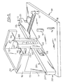
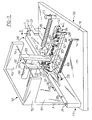
- the device for driving an active member in accordance with the present invention comprises a base 100, a lever 200 which supports the active member schematically referenced S, a link 300, a latch 400 and two pushers 500 and 600.
- the base 100 comprises a generally horizontal plate 110 whose upper surface is referenced 111.
- the plate 110 carries a console 150 whose structure will be described in more detail below.
- the plate 110 carries on its upper surface a stud 112 and two rods 113 and 114.
- the stud 112 constitutes one of the elements of the guide means capable of guiding the rod 300 in translation over a controlled amplitude.
- the two rods 113 and 114 are intended to receive, as shown in FIGS. 6 to 8, one of the ends of respective springs 700 and 800 ensuring one the return of the lever 200 to the rest position, the other the return of the latch 400 in the locked position.
- the stud 112 and the rods 113, 114 are each cylindrical and extend projecting and perpendicularly on the upper surface 111 of the plate 110.
- the lever 200 is formed of a substantially rectilinear bar which extends horizontally and rests on the upper surface 111 of the plate 110.
- the lever 200 has a cross section (considered transversely to its direction of elongation) generally rectangular. More specifically, preferably, as shown in the figures, the largest dimension of the cross section of the lever extends perpendicular to the surface 111 of the plate 110 of the base, while the small dimension of the cross section of the lever 200 extends parallel to the upper surface 111.
- the lever 200 is pivotally mounted on the base 100 by a first end 210 around a main axis referenced A.
- This axis A extends perpendicular to the direction of elongation of the lever 200 and parallel to the largest dimension of the cross section of the lever 200.
- the main pivot axis A of the lever 200 extends perpendicular to the upper surface 111 of the base.
- the main pivot axis A of the lever 200 is materialized by a shaft referenced 211 passing through the lever 200 and engaged in the plate 110 of the base 100.
- the lever 200 carries the active member S, such as a tachograph stylus.
- the stylus S is shown schematically in the form of a point extending parallel to the axis A, and passing through a finger 221 secured to the body of the lever 200.
- the stylus S is preferably associated with a displacement member and with elastic biasing means capable of controlling the contacting of the tip of the stylus S against a tachograph disc.
- the drive means and elastic biasing of the stylus S conventional in themselves, have not been shown in the figures, in order to simplify the illustration.
- the lever 200 is further provided with a longitudinal slot schematically referenced 230.
- This slot 230 extends parallel to the direction of extension of the bar 200.
- This slot 230 crosses the lever 200 perpendicularly to the large longitudinal faces of the latter, that is to say parallel to the upper surface 111 of the base 110.
- This slot 230 as illustrated in Figures 6, 7 and 8 is intended to receive a portion of the rod 300 and the lock 400 superimposed.
- the lever 200 is provided between the longitudinal slot 230 and the aforementioned second end 220 with a through hole 240 in which the second end of the aforementioned biasing spring 700 is engaged.
- the rod 300 is formed of an L-shaped plate which, in use, extends generally parallel to the plate 110 of the base.
- the two wings of the link 300 are referenced 310 and 320 respectively in the figures.
- the wing 310 of the link 300 When the drive device is assembled, the wing 310 of the link 300 is engaged in the longitudinal slot 230, while the wing 320 of the link 300 extends transversely to the lever 200.
- an oblong opening 321 is formed connecting the main horizontal faces of the - link 300 and extending generally parallel to the direction of elongation of the second wing 320. of the assembly, the light 321 receives a journal 430 by means of which the lock 400 is articulated on the lever 200.
- the light 321 is preferably formed by two semi-cylindrical caps 330, 331 complementary to the external surface of the pin 430, connected by two flat surfaces, 332, 333 parallel to each other and parallel to the direction of elongation of the second wing 320 of the link 300.
- the length of the aforementioned flat faces of the light 321 determines the amplitude of the relative movement allowed between the lever 200 and the link 300.
- the second wing 320 of the link 300 is provided with an oblong recess 322 also connecting the main horizontal faces of the link 300.
- this elongate recess 322 extends substantially parallel to the direction of elongation of the second wing 320 of the link 300.
- This recess 322 receives the stud 112 integral with the base 100.
- the recess 322, preferably, is delimited by two semi-cylindrical caps 340, 341, complementary to the outer envelope of the stud 112, connected by two flat surfaces 342, 343 mutually parallel and parallel to the direction of elongation of the second wing 320 of the rod 300.
- the length of the flat faces 342 and 343 defines the amplitude of the relative displacement authorized between the link 300 and the base 100.
- the second wing 320 of the link 300 is further provided between the light 321 and the recess 322 above, with a cylindrical rod 323 projecting perpendicularly on its upper surface.
- the second wing 320 of the rod 300 is provided with an opening 324, crossing the thickness of the rod 300 considered between its two main horizontal faces and which opens onto the extreme edge 327 of the second wing 320.
- the opening 324 comprises on the one hand a channel 326 extending parallel to the direction of elongation of the second wing 320, substantially in alignment with the light 321 and the recess 322, and on the other hand a recess which defines a bearing surface 325 which extends transversely to the direction of elongation of the wing 320, and therefore substantially transversely to the direction of movement of the rod 300 relative to the base 100.
- the bearing surface 325 is directed towards the edge 327. If necessary, the bearing surface 325 can be slightly inclined towards channel 326.
- the opening 324 is intended to cooperate with a projecting member 423 provided on the lower surface of the lock 400.
- the displacement of the projecting member 423 in the opening 324 away from the transverse surface 325, facing the channel 326, is preferably limited by the lateral surface of the channel referenced 328 in FIG. 3, which extends transversely to the aforementioned surface 325, in order to guarantee the penetration of the projection 423 into the channel 326.
- Such a limitation of the relative pivoting between the link 300 and the latch 400 may be obtained by any other functionally equivalent means, for example by means of the stud 112 entering an opening 422 (which will be defined in more detail below) formed in the latch 400.
- the latch 400 which, in use, is superimposed on the rod 300 and also extends parallel to the plate 110 is formed of a plate in the general shape of "L".
- the two wings of the lock 400 are referenced 410, 420 respectively in the figures.
- the first wing 410 of the lock 400, engaged in the longitudinal slot 230 of the lever 200 is provided with a through hole 411 oriented perpendicular to its main faces, and intended to receive the second end of the aforementioned biasing spring 800.
- the lock 400 is provided in the angle adjacent to the wings 410 and 420 with a pin 430 projecting on either side, engaged in the slot 321 of the rod 300 and by means of which the lock 400 is articulated on the lever 200.
- the second wing 420 of the lock 400 is provided near its free end and on its lower surface with a cylindrical projection 423 cooperating, according to an arrangement which will be described in more detail below, with the opening 324 of the rod 300.
- the second wing 420 of the latch 400 is provided with more than a first through opening 421, of generally rectangular outline, in which the above-mentioned rod 323 of the rod 300 is engaged.
- the first opening 421 is shaped to allow relative movement of the rod 300 and the lock 400 on the one hand and the contacting of the first pusher 500 and the control rod 323 on the other hand, as shown in Figures 6 to 8
- the second wing 420 of the lock 400 is further provided with a second through opening 422, of generally rectangular outline, in which the stud 112 is engaged.
- This second opening 422, as shown in FIGS. 6 to 8, is shaped to allow relative movement of the latch 400 and the stud 112.
- the distance separating the pin 430 from the projection 423 on the latch is equal to the distance separating the bearing surface 325 from the semi-cylindrical cap 331 on the link.
- the drive device further comprises two pushers 500 and 600 intended to drive respectively the link 300 and the latch 400.
- the pushers 500, 600 are formed of bars generally rectilinear, extending vertically at rest, and pivotally mounted, by their upper end 501, 601 around a horizontal axis 154 carried by the console 150.
- the console 150 is formed of a vertical plate 151 carried by the plate 110 and provided with two parallel wings 152, 153 on which the above-mentioned axis 154 is immobilized.
- the lower end 502 of the pusher 500 is engaged in the opening 421 of the latch 400 and can come to bear against the control rod 323 of the rod 300, on the side of the opening 324.
- the lower end 602 of the second pusher 600 rests against the edge 412 of the first wing 410 of the latch 400, directed towards the second wing 420, and situated between the through orifice 411 and the abovementioned opening 421.
- the edge 412 is not planar but cylindrical, as shown in FIG. 4.
- the console 150 is adapted to support the axis 154 of articulation of the pushers 500 and 600 so that the lower end 502 and 602 of the latter is placed on the same side of the lever 200 as the stud 112 and the support rods 113 , 114.
- the plate 151 of the console 150 also supports two electromagnets 160, 170 arranged respectively opposite the first pusher 500 and the second pusher 600 and adapted, when supplied, to induce a respective pivoting of the pusher 500 and 600 around the horizontal axis 154, tending to bring the lower end 502, 602 closer to the pushers, to the lever 200.
- the structure of the pushers 500, 600, of the console 150 and of the electromagnets 160, 170 can be the subject of numerous variant embodiments.
- the wings 310 and 410 of the link 300 and the latch 400 are engaged in the longitudinal slot 230 of the lever 200.
- the latch 400 is articulated by means of the journal 430 extending parallel to the axis A, on the lever 200 .
- the ends of the spring 800 are engaged respectively in the orifice 411 of the latch 400 and on the support rod 114 secured to the base 100.
- the latch 400 is biased by the spring 800 towards a locking position in which the projection 423 engaged in the opening 324 of the rod 300 is urged away from the channel 326 and rests against the bearing surface 325.
- the pin 430 then rests against the semi-cylindrical cap 331 of the rod 300.
- the ends of the second spring 700 are engaged respectively on the support rod 113 integral with the base 100 and in the orifice 240 of the lever 200.
- the second spring 700 urges the lever 200 into approximation of the support rod 113.
- the spring 700 urges - a movement of the rod 300 away from the console 150 until put in contact with the stud 112 secured to the base 100 and the semi-cylindrical cap 340 of the recess 322 formed in the link 300.
- the contacting of the stud 112 and the semi-cylindrical cap 340 of the recess 322 limits the movement of the lever 200 in approach to the support rod 113 and defines the rest position of the support lever.
- the supply of the first electromagnet 160 induces the pivoting of the first pusher 500 around the axis 154, and tends to bring the lower end 502 of the first pusher 500 of the lever 200, as illustrated by the arrow referenced B in the figure 7.
- the lever 200 is then brought to the auxiliary working position.
- the spring 800 constantly urges the projection 423 of the latch 400 away from the channel 326, bearing against the transverse surface 325.
- the latch 400 accompanies the rod 300 when the lever 200 moves from the rest position (FIG. 6) to the auxiliary working position (figure 7).
- the lock 400 articulated on the lever 200 by means of the journal 430 prevents movement of the lever 200 beyond the auxiliary working position since, on the one hand, the semi-cylindrical surface 341 of the rod 300 rests against the stud. 112 secured to the base and on the other hand the projection 423 secured to the latch 400 rests against the transverse bearing surface 325 of the rod 300.
- the link rests by means of the semi-cylindrical surface 341 against the stud 112.
- the projection 423 of the latch 400 is engaged in the channel 326 of the link 300 and the pin 430 rests against the semi-cylindrical surface 330 of the link 300 to limit the movement of the lever 200.
- the springs 700 and 800 of course ensure the return of the lever 200 in rest position and of the latch 400 in the blocking position, at the end of the supply of the electromagnets 160 and 170. Nevertheless, those skilled in the art will easily understand that thanks to the structure previously described, when from the main working position obtained by supplying the electromagnet 170, the supply of the latter is cut off but the supply of the electromagnet 160 is maintained (or carried out in synchronism with the power supply to the electromagnet 170), the lever 200 is returned to the auxiliary working position and the latch 400 is returned to the blocking position.
- the journal 430, the stud 112, the light 321 and the recess 322 are dimensioned so that the movement of the stud 112 in the recess 322, parallel to the direction of elongation of the wing 320 of the link 300 is of an amplitude substantially identical to the movement of the journal 430 in the slot 321.
- the auxiliary working position of the active member S is located halfway between the rest position and the main working position.
- control rod 323 of the rod 300 can be eliminated and replaced by a bore in which the lower end 502 of the first pusher 500 is engaged.
- the stud 112 secured to the base 100 can be removed and replaced by an oblong opening in which is engaged a stud secured to the link 300.
- the opening 324 formed on the link 300 and the projection 423 produced on the lock 400 could be replaced by equivalent means comprising a projection integral with the link cooperating with an opening made in the lock 400 and defining a surface transverse support to the direction of movement of the rod as well as a channel oriented parallel to this direction.
- the orientation of the bearing surface and the channel should be reversed with respect to the arrangement illustrated in the figures, that is to say that the bearing surface should be directed towards the pin 430 and the channel away from it.
- journal 430 engaged in the lumen 321 of the link 300 and by means of which the lock 400 is articulated on the lever 200, by an axis integral with the link 300 , engaged in an oblong opening formed in the lever 200, the latch 400 being articulated on the lever 200 by means of an auxiliary journal parallel to the aforementioned axis.
- the support part carrying the active member S formed by a pivoting lever according to the particular embodiment which has just been described, may be replaced by a support part guided in translation on the base, parallel to the direction of translation of the rod, as previously mentioned.
Landscapes
- Physics & Mathematics (AREA)
- General Physics & Mathematics (AREA)
- Mechanical Control Devices (AREA)
- Feeding And Guiding Record Carriers (AREA)
- Time Recorders, Dirve Recorders, Access Control (AREA)
- Toys (AREA)
Applications Claiming Priority (2)
| Application Number | Priority Date | Filing Date | Title |
|---|---|---|---|
| FR8418456A FR2574186B1 (fr) | 1984-12-04 | 1984-12-04 | Dispositif d'entrainement d'un organe actif tel qu'un stylet de tachygraphe entre une position de repos et deux positions de travail |
| FR8418456 | 1984-12-04 |
Publications (2)
| Publication Number | Publication Date |
|---|---|
| EP0184509A1 true EP0184509A1 (de) | 1986-06-11 |
| EP0184509B1 EP0184509B1 (de) | 1988-10-12 |
Family
ID=9310201
Family Applications (1)
| Application Number | Title | Priority Date | Filing Date |
|---|---|---|---|
| EP85402367A Expired EP0184509B1 (de) | 1984-12-04 | 1985-12-02 | Anordnung zum Antreiben eines aktiven Elementes wie z.B. eines Tachigraphenstichels zwischen einer Ruheposition und zwei Arbeitspositionen |
Country Status (6)
| Country | Link |
|---|---|
| EP (1) | EP0184509B1 (de) |
| KR (1) | KR900003167B1 (de) |
| DE (1) | DE3565603D1 (de) |
| ES (1) | ES8707800A1 (de) |
| FR (1) | FR2574186B1 (de) |
| TR (1) | TR22358A (de) |
Citations (2)
| Publication number | Priority date | Publication date | Assignee | Title |
|---|---|---|---|---|
| GB692716A (en) * | 1949-06-15 | 1953-06-10 | Werner Joens | An improved switch mechanism for electrical supervision or control equipment |
| GB2017918A (en) * | 1978-03-31 | 1979-10-10 | Kienzle Apparate Gmbh | Recording arrangement |
-
1984
- 1984-12-04 FR FR8418456A patent/FR2574186B1/fr not_active Expired
-
1985
- 1985-12-02 DE DE8585402367T patent/DE3565603D1/de not_active Expired
- 1985-12-02 EP EP85402367A patent/EP0184509B1/de not_active Expired
- 1985-12-03 KR KR1019850009063A patent/KR900003167B1/ko not_active Expired
- 1985-12-04 TR TR48914A patent/TR22358A/xx unknown
- 1985-12-04 ES ES550406A patent/ES8707800A1/es not_active Expired
Patent Citations (2)
| Publication number | Priority date | Publication date | Assignee | Title |
|---|---|---|---|---|
| GB692716A (en) * | 1949-06-15 | 1953-06-10 | Werner Joens | An improved switch mechanism for electrical supervision or control equipment |
| GB2017918A (en) * | 1978-03-31 | 1979-10-10 | Kienzle Apparate Gmbh | Recording arrangement |
Also Published As
| Publication number | Publication date |
|---|---|
| KR900003167B1 (ko) | 1990-05-09 |
| EP0184509B1 (de) | 1988-10-12 |
| DE3565603D1 (en) | 1988-11-17 |
| ES550406A0 (es) | 1987-08-16 |
| FR2574186A1 (fr) | 1986-06-06 |
| KR860005214A (ko) | 1986-07-18 |
| FR2574186B1 (fr) | 1987-02-27 |
| TR22358A (tr) | 1987-02-24 |
| ES8707800A1 (es) | 1987-08-16 |
Similar Documents
| Publication | Publication Date | Title |
|---|---|---|
| EP0337856B1 (de) | Lösbare Baugruppe für eine elektrische oder elektronische Anlage, bestehend aus einem Gehäuse und dessen Gestell | |
| EP0081401B1 (de) | System zur zeitweiligen Festlegung und Freigabe zweier Teile, insbesondere in der Raumfahrttechnik | |
| EP1000832B1 (de) | Drehbarer Sitz, insbesondere für ein Schienenfahrzeug | |
| CH689671A5 (fr) | Dispositif d'introduction de feuilles ou d'enveloppes à imprimer. | |
| EP1729376B1 (de) | Verriegelungshebelmechanismus für Verbinder | |
| CH691799A5 (fr) | Imprimante. | |
| EP4353598A1 (de) | Hakenschloss für eine flugzeugplatte | |
| EP0184509B1 (de) | Anordnung zum Antreiben eines aktiven Elementes wie z.B. eines Tachigraphenstichels zwischen einer Ruheposition und zwei Arbeitspositionen | |
| EP0305245B1 (de) | Verriegelung eines Deckels auf einem Rahmen | |
| EP0055662B1 (de) | Ergonomisches Sichtanzeigesystem mit automatischer Einstellung des Leseabstandes in Abhängigkeit vom Kippwinkel des Bildschirmes | |
| FR2601609A1 (fr) | Systeme pour l'immobilisation d'une piece reposant sur un support. | |
| CH688495B5 (fr) | Pièce d'horlogerie comportant un mécanisme de commande à tige et à tirette. | |
| EP0311523B1 (de) | Bistable Schalter, insbesondere zur Betätigung von Abblend- und Fernlicht von Fahrzeugen | |
| FR2599550A1 (fr) | Commutateur pour vehicules automobiles | |
| EP1751403B1 (de) | Ventiltriebvorrichtung | |
| EP0252800A1 (de) | Schalter, insbesondere für die Steuerung von Wisch-Wasch-Kombinationen von Kraftfahrzeugen | |
| FR2663605A1 (fr) | Poste de pilotage d'aeronef equipe d'une bibliotheque electronique de bord. | |
| EP0237690B1 (de) | Verschiebbarer Druckkopf | |
| EP1293371B1 (de) | Verbindungsanordnung und entsprechendes Kraftfahrzeug | |
| EP0046830B1 (de) | Präzisionszirkel mit gelenkigem Schenkel und steifer Stange | |
| CH672204A5 (de) | ||
| FR2649027A1 (fr) | Porte-outil de machine-outil associe a un dispositif de connexions automatiques | |
| EP4215078B1 (de) | An mindestens zwei gurtbreiten eines gurtes anpassbare gürtelschnalle und gürtel mit einer solchen schnalle | |
| EP1069813B1 (de) | Frontplatte für eine elektronische Baugruppe, elektronische Baugruppe, und deren Einschub- oder Ausziehverfahren aus einem Baugruppenträger | |
| EP4257004B1 (de) | Armbandverschluss |
Legal Events
| Date | Code | Title | Description |
|---|---|---|---|
| PUAI | Public reference made under article 153(3) epc to a published international application that has entered the european phase |
Free format text: ORIGINAL CODE: 0009012 |
|
| AK | Designated contracting states |
Kind code of ref document: A1 Designated state(s): DE GB IT SE |
|
| 17P | Request for examination filed |
Effective date: 19860707 |
|
| 17Q | First examination report despatched |
Effective date: 19880223 |
|
| GRAA | (expected) grant |
Free format text: ORIGINAL CODE: 0009210 |
|
| AK | Designated contracting states |
Kind code of ref document: B1 Designated state(s): DE GB IT SE |
|
| PG25 | Lapsed in a contracting state [announced via postgrant information from national office to epo] |
Ref country code: SE Effective date: 19881012 |
|
| GBT | Gb: translation of ep patent filed (gb section 77(6)(a)/1977) | ||
| REF | Corresponds to: |
Ref document number: 3565603 Country of ref document: DE Date of ref document: 19881117 |
|
| ITF | It: translation for a ep patent filed | ||
| PLBE | No opposition filed within time limit |
Free format text: ORIGINAL CODE: 0009261 |
|
| STAA | Information on the status of an ep patent application or granted ep patent |
Free format text: STATUS: NO OPPOSITION FILED WITHIN TIME LIMIT |
|
| 26N | No opposition filed | ||
| PGFP | Annual fee paid to national office [announced via postgrant information from national office to epo] |
Ref country code: GB Payment date: 19911126 Year of fee payment: 7 |
|
| PG25 | Lapsed in a contracting state [announced via postgrant information from national office to epo] |
Ref country code: GB Effective date: 19921202 |
|
| ITTA | It: last paid annual fee | ||
| PGFP | Annual fee paid to national office [announced via postgrant information from national office to epo] |
Ref country code: DE Payment date: 19930125 Year of fee payment: 8 |
|
| GBPC | Gb: european patent ceased through non-payment of renewal fee |
Effective date: 19921202 |
|
| PG25 | Lapsed in a contracting state [announced via postgrant information from national office to epo] |
Ref country code: DE Effective date: 19940901 |