EP0184587A1 - Opérateur robotique pour terminal d'ordinateur - Google Patents
Opérateur robotique pour terminal d'ordinateur Download PDFInfo
- Publication number
- EP0184587A1 EP0184587A1 EP84115017A EP84115017A EP0184587A1 EP 0184587 A1 EP0184587 A1 EP 0184587A1 EP 84115017 A EP84115017 A EP 84115017A EP 84115017 A EP84115017 A EP 84115017A EP 0184587 A1 EP0184587 A1 EP 0184587A1
- Authority
- EP
- European Patent Office
- Prior art keywords
- terminal
- microprocessor
- station according
- computer system
- robot
- Prior art date
- Legal status (The legal status is an assumption and is not a legal conclusion. Google has not performed a legal analysis and makes no representation as to the accuracy of the status listed.)
- Granted
Links
Images
Classifications
-
- G—PHYSICS
- G06—COMPUTING OR CALCULATING; COUNTING
- G06F—ELECTRIC DIGITAL DATA PROCESSING
- G06F3/00—Input arrangements for transferring data to be processed into a form capable of being handled by the computer; Output arrangements for transferring data from processing unit to output unit, e.g. interface arrangements
- G06F3/01—Input arrangements or combined input and output arrangements for interaction between user and computer
- G06F3/048—Interaction techniques based on graphical user interfaces [GUI]
- G06F3/0487—Interaction techniques based on graphical user interfaces [GUI] using specific features provided by the input device, e.g. functions controlled by the rotation of a mouse with dual sensing arrangements, or of the nature of the input device, e.g. tap gestures based on pressure sensed by a digitiser
- G06F3/0489—Interaction techniques based on graphical user interfaces [GUI] using specific features provided by the input device, e.g. functions controlled by the rotation of a mouse with dual sensing arrangements, or of the nature of the input device, e.g. tap gestures based on pressure sensed by a digitiser using dedicated keyboard keys or combinations thereof
Definitions
- This invention relates to an apparatus for simulating a human user or operator at a terminal workstation connected to a computer system, and more specifically to a programmable apparatus adapted to be attached to a terminal station and capable to receive and interpret the human readable information supplied by the computer system to the terminal and to respond to this information with messages or commands, thus simulating a human user.
- this invention provides a robot operator with the capability to watch the availability of a computer system, the robot being programmed to respond on system failure with a telephone call to the human operator, thus allowing unattended functioning of a large computer system, e.g. during off-hours.
- the interactive communication between the user and the computer system occurs according to predetermined protocols in human readable form, the user commands and system responses being displayed on the terminal screen.
- the well defined sequence of user commands and system responses itself may be controlled by a microprocessor to assist or to replace the user. Up till now such a device was not available.
- Computer systems are often active during non-office hours e.g. for processing big jobs in batch mode or other purposes. Although the system operates independently, the system operator has to be present to restart the system in case of failure. As the system operator has to cope with the exception, a robot operator for watching an unattended system is desirable.
- Signaling computer failure by another computer is also known in itself, e.g. in telephone exchanges two parallel operating computers are used and upon failure of one system, the back-up system takes over under signaling the malfunctioning. Again, the computers do not mutually communicate in human readable information.
- Diagnostic programs checking computer failures are also well known and widely used. Such programs are internal computer activities invoked for checking the correctness of each specific function in the machine before the machine becomes operative, but they do not monitor and control the normal or exceptional functioning of the entire system, as would a human operator by his attention and interventions.
- the first object of the invention is to provide a robot operator capable to handle an interactive session at a computer terminal, thus replacing the human end-user.
- Another object of the invention is to provide a programmable device, capable to retrieve and analyse the human understandable information at terminal level and to respond to the computer system with adequate commands and information.
- a further object of the invention is to provide a combination of software and hardware means adapted to be connected to a terminal workstation for simulating the human user during his or her absence.
- a further object of the invention is to provide an intelligent terminal equipped with a microprocessor for independent communication with a computer system.
- a further object of the invention is to provide a robot operator capable to check the operation and functioning of the computer system to which it is connected, and to react upon detection of system failure by calling the human operator for assistance.
- Another object of the invention is to provide a programmable device connected to several systems and capable to send messages on one of the systems to signal malfunctioning of another system.
- Still a further object of the invention is to provide a robot operator, capable to make a phone call upon predetermined occurrences, such as malfunctioning of a computer system.
- Another object of the invention is to provide robot operator equipped with a microprocessor, programmable for log-on and further procedures for interactive communication with a data processing system, thus simulating the human user served by the computer system.
- a conventional terminal station is provided with an additional programmable device comprising a microprocessor, connected to the terminal line through a deserializer, and a keyboard simulator, switchably connected to the terminal for replacing the human operated keyboard.
- the robot apparatus is connected to a telephone exchange, while a local printer, indicator lights and alarms may be provided for complete functioning of the device.
- the robot control program is entered in the form of one or more ROM's for ensuring reliable functioning of the programmable device, especially in case the robot is used to check the correct operation of the system to which it is attached.
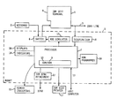
- the drawing shows a terminal workstation with additional hardware to illustrate a preferred embodiment of the invention.
- a terminal 1 and a keyboard 2 constitute a conventional terminal station, connected to a mainframe computer system through a coax line 3 for interactive communication with the system in human readable form.
- the commands, data or information entered by the user through keyboard 2 are supplied to a buffer storage within the terminal, for display on the frontscreen 4 and, upon pressing a special key such as the enter-key or a function-key, the contents of the terminal buffer storage is transferred to the computer.
- Responses of the computer are also supplied to the terminal buffer and displayed on the terminal screen 4, thus allowing human readable interactive communication with the computer system.
- These terminal workstations are well known in the art and are widely used.
- the terminal workstation consisting of terminal 1 and keyboard 2 is equipped with a robot apparatus, in the drawing generally indicated with 5.
- a toggle switching device 6 connects terminal 1 and keyboard 2 the terminal station functions as a normal user operated station, but in the alternative position of switch 6 the keyboard 2 is disconnected and the powered robot 5 is active.
- the robot is equipped and programmed to use the terminal 1 for interactive communication with the computer system, thus replacing and simulating the human user.
- a microprocessor 7 in the robot apparatus 5 is connected to the coax line 3 through a deserializer 8, such that the serial data supplied by the computer system to the terminal 1 for display on screen 4, via line 3, is also received by the microprocessor 7.
- Microprocessor 7 contains a random access memory 9 for storing the information supplied by the computer system and a read only storage 10 for storing the robot programs.
- a microprocessor of the Motorola 6800 series was used to run the robot device, but other commercially available microprocessors may serve this purpose equally.
- Microprocessor 7 is programmed to store and then analyse the information received from the computer system as stored in RAM 9 and to generate a response, e.g. a further command to the system. Thereto, the output of the microprocessor 7 is supplied to the keyboard simulator 11, connected by switch 6 to terminal 1 and replacing the keyboard 2.
- the keyboard simulator is a conventional device, also known as a computer port, suitable for supplying characters to the terminal in the same manner as a human operated keyboard, under control of the microprocessor.
- the robot apparatus 5 further contains an attachment 12 for connecting the microprocessor 7 to a telephone exchange system (such as, an IBM 3750) and also a further connection 13 to a host computer is provided.
- the host connection 13 allows to enter the robot programs written under the editor of the host computer and the finished robot programs are downloaded from the host into the microprocessor memory for controlling the robot operation.
- the ROM programmer 18 provides a means to transfer the robot program into a permanent form by imprinting the code in a ROM chip, e.g. an EPROM (erasable programmable read only memory) commercially available from Intel Corp. or other suppliers.
- a local printer 17 is connected to microprocessor 7 for printing robot messages.
- the terminal workstation operates as a normal computer terminal when switch 6 connects keyboard 2 to terminal 1.
- the user may log on to the system according to the predetermined procedure from the powered terminal when the system logo or a similar indication is displayed, signaling that the system is available and accessible from this terminal.
- the user will log-on by supplying his unique user identification and password to the system in order to be connected for service.
- the system logo will be a unique picture frame visually identifying the computer system on the display screen.
- the information and commands entered by the user are stored in the terminal buffer and displayed on the screen, while upon pressing the ENTER key, or a function key, the information is transferred from the terminal buffer to the computer system through line 3.
- the computer responds with a complete frame of 25 lines with 80 characters each, which are entered in the terminal buffer and displayed on screen 4, whereupon the user may enter the next information and command in the interactive communication with the computer.
- the robot is activated by powering on and putting switch 6 in the position to connect the keyboard simulator 11 to terminal 1.
- the information supplied by the computer e.g. the system logo, is loaded into the robot memory upon a first entry from the robot, which may be a single simulated pressing of the ENTER key performed by KBD simulator 11.
- the serial data supplied by the responding computer system is assembled into 8-bit bytes by the deserializer 8 and supplied to the microprocessor 7 for subsequent storing in a screen buffer area of 2000 bytes in the Random Access Memory 9 of the microprocessor, as well as being displayed on frontscreen 4 of terminal 1.
- Microprocessor 7 is programmed to analyse the data supplied by the computer system and stored in RAM 9, and to generate a response or action in accordance with predetermined instructions of the user.
- the robot may handle the log-on procedure and subsequent commands. Examples of the different detailed operations carried out by the microprocessor 7 on the information supplied by the system are given in the next chapter titled Robot Instructions.
- the response generated by the microprocessor is supplied to the keyboard simulator 11 for a subsequent character by character input into the terminal storage, thus simulating an entry of a human user.
- the robot may be instructed to make a phone call to the system operator in response to certain data supplied by the computer or absence thereof, as illustrated in the next chapter, Robot Instructions.
- robot instructions cause the robot to print messages upon occurrence of certain conditions, e.g. upon detection of internal failure.
- the robot device is further provided with indicator lights and a display panel controlled by the robot program and adapted to visualize the robot functioning.
- a set of high-level instructions is provided for the user to program the robot microprocessor. To further illustrate the operation of the device some of the instructions are specified below by way of a non limitative example. For each instruction the corresponding operation and the format is specified.
- a function code corresponding to a selected function key (PF1 - PF12) of the human operated keyboard as specified by 'keyid' will be transferred by the keyboard simulator to the terminal, upon the execution of this instruction.
- This instruction will read data passing along the coax cable into the screen buffer.
- This instruction will search the copy of the screen buffer contents to detect a series of characters equal to the string supplied with the instruction, and branch if the search is successful.
- This instruction will turn indicators on and off. Format: LAMP local/remote, green/red, nn, off/on in which nn specifies the lamp number.
- This instruction will save a part of the screen buffer in a 512-byte area.
- This instruction will compare data in the 512-byte area with data in the screen buffer.
- This instruction will print data from the 512-byte save area.
- This instruction will dial a telephone number.
- This instruction will send audio tones over the telephone.
- This instruction will cause a wait.
- the computer system displays its logo on all connected powered terminals to inform the users about the availability of the system.
- a listing of these systems is displayed on the terminal screen with for each system the indication 'on-line'.
- the logo disappears, or, respectively, the indication 'on-line' is replaced by 'off-line'.
- the robot operator attached to any terminal of the computer system may be programmed to read the system logo or, respectively, the on-line indication, and to detect the absence of the logo or the presence of an off-line indication upon system failure.
- This feature of the robot operator is particularly attractive because it allows unattended operation of even a large computer system during off-hours when big jobs in batch mode are processed.
- the robot processor may be programmed to make a phone call to the operator, or take any other adequate action, such as signalling a guard, buzzing or sending a message through another system available at the terminal.
- Robot programs may be written under the facilities of the host computer, and then be stored on the disk memory of the host computer and loaded down into RAM 9 when needed, using host computer connection 13.
- the robot is provided with a ROM programmer 18 capable to write the program from RAM 9 into a ROM chip (EPROM), thus ensuring a reliable operation of the robot controlled by a program in a permanent form.
- EPROM ROM chip
Landscapes
- Engineering & Computer Science (AREA)
- General Engineering & Computer Science (AREA)
- Theoretical Computer Science (AREA)
- Human Computer Interaction (AREA)
- Physics & Mathematics (AREA)
- General Physics & Mathematics (AREA)
- Debugging And Monitoring (AREA)
- Numerical Control (AREA)
Priority Applications (3)
| Application Number | Priority Date | Filing Date | Title |
|---|---|---|---|
| DE8484115017T DE3481787D1 (de) | 1984-12-11 | 1984-12-11 | Roboter-bediener fuer ein rechnerterminal. |
| EP19840115017 EP0184587B1 (fr) | 1984-12-11 | 1984-12-11 | Opérateur robotique pour terminal d'ordinateur |
| JP23146985A JPS61139804A (ja) | 1984-12-11 | 1985-10-18 | ロボツト装置 |
Applications Claiming Priority (1)
| Application Number | Priority Date | Filing Date | Title |
|---|---|---|---|
| EP19840115017 EP0184587B1 (fr) | 1984-12-11 | 1984-12-11 | Opérateur robotique pour terminal d'ordinateur |
Publications (2)
| Publication Number | Publication Date |
|---|---|
| EP0184587A1 true EP0184587A1 (fr) | 1986-06-18 |
| EP0184587B1 EP0184587B1 (fr) | 1990-03-28 |
Family
ID=8192341
Family Applications (1)
| Application Number | Title | Priority Date | Filing Date |
|---|---|---|---|
| EP19840115017 Expired EP0184587B1 (fr) | 1984-12-11 | 1984-12-11 | Opérateur robotique pour terminal d'ordinateur |
Country Status (3)
| Country | Link |
|---|---|
| EP (1) | EP0184587B1 (fr) |
| JP (1) | JPS61139804A (fr) |
| DE (1) | DE3481787D1 (fr) |
Citations (5)
| Publication number | Priority date | Publication date | Assignee | Title |
|---|---|---|---|---|
| GB1116450A (en) * | 1964-12-03 | 1968-06-06 | Ass Elect Ind | Improvements relating to digital computer equipment |
| US4088981A (en) * | 1975-11-12 | 1978-05-09 | Citibank N.A. | Automated data entry and display system |
| US4272813A (en) * | 1979-04-02 | 1981-06-09 | International Business Machines Corporation | Communicating typewriter and dictation system utilizing analog recording and transmission techniques |
| US4377852A (en) * | 1980-03-31 | 1983-03-22 | Texas Instruments Incorporated | Terminal emulator |
| EP0111130A2 (fr) * | 1982-12-03 | 1984-06-20 | International Business Machines Corporation | Ordinateur à plusieurs terminaux |
Family Cites Families (3)
| Publication number | Priority date | Publication date | Assignee | Title |
|---|---|---|---|---|
| JPS57176459A (en) * | 1981-04-24 | 1982-10-29 | Mitsubishi Electric Corp | Simulator for key switch |
| JPS58154056A (ja) * | 1982-03-08 | 1983-09-13 | Hitachi Ltd | 端末装置 |
| JPS59211131A (ja) * | 1983-05-17 | 1984-11-29 | Nec Corp | 端末装置のフアイル送受信方式 |
-
1984
- 1984-12-11 DE DE8484115017T patent/DE3481787D1/de not_active Expired - Lifetime
- 1984-12-11 EP EP19840115017 patent/EP0184587B1/fr not_active Expired
-
1985
- 1985-10-18 JP JP23146985A patent/JPS61139804A/ja active Pending
Patent Citations (5)
| Publication number | Priority date | Publication date | Assignee | Title |
|---|---|---|---|---|
| GB1116450A (en) * | 1964-12-03 | 1968-06-06 | Ass Elect Ind | Improvements relating to digital computer equipment |
| US4088981A (en) * | 1975-11-12 | 1978-05-09 | Citibank N.A. | Automated data entry and display system |
| US4272813A (en) * | 1979-04-02 | 1981-06-09 | International Business Machines Corporation | Communicating typewriter and dictation system utilizing analog recording and transmission techniques |
| US4377852A (en) * | 1980-03-31 | 1983-03-22 | Texas Instruments Incorporated | Terminal emulator |
| EP0111130A2 (fr) * | 1982-12-03 | 1984-06-20 | International Business Machines Corporation | Ordinateur à plusieurs terminaux |
Non-Patent Citations (3)
| Title |
|---|
| IBM TECHNICAL DISCLOSURE BULLETIN, vol. 23, no. 9, February 1981, page 4006, Armonk, US; C.H. SEDERHOLM et al.: "Intelligent telephone" * |
| PATENTS ABSTRACTS OF JAPAN, vol. 6, no. 46 (P-107)[924], 24th March 1982; & JP - A - 56 162 123 (HITACHI SEISAKUSHO K.K.) 12-12-1981 * |
| PATENTS ABSTRACTS OF JAPAN, vol. 8, no. 55 (P-260)[1492], 13th March 1984; & JP - A - 58 203 565 (HITACHI SEISAKUSHO K.K.) 28-11-1983 * |
Also Published As
| Publication number | Publication date |
|---|---|
| DE3481787D1 (de) | 1990-05-03 |
| EP0184587B1 (fr) | 1990-03-28 |
| JPS61139804A (ja) | 1986-06-27 |
Similar Documents
| Publication | Publication Date | Title |
|---|---|---|
| US3866175A (en) | Data communication system between a central computer and a plurality of data terminals | |
| US4991123A (en) | Alarm system | |
| US4354252A (en) | Programmable digital data terminal for mobile radio transceivers | |
| US4216462A (en) | Patient monitoring and data processing system | |
| EP0310788B1 (fr) | Système permettant l'interchangeabilité des périphériques | |
| US5398280A (en) | Paging system for remote computers | |
| EP0205949A2 (fr) | Emulateur pour adaptateurs d'entrée-sortie d'un système ordinateur | |
| EP0076903B1 (fr) | Emulation de terminaux d'affichage de traitement de données à dimensions variables d'écran sur l'affichage d'un processeur de texte | |
| JPS59501525A (ja) | 無線通信システム | |
| JPH03282581A (ja) | 価格表示システム及びそれに関連する方法 | |
| US5119088A (en) | Method for the identification of peripheral equipment within a digital communication system | |
| WO1998057479A1 (fr) | Interface de transmission de donnees connectee en ligne entre un clavier et un port de clavier d'ordinateur personnel | |
| EP0184587B1 (fr) | Opérateur robotique pour terminal d'ordinateur | |
| JPS6176000A (ja) | 防災表示装置 | |
| EP0335962B1 (fr) | Systeme d'affichage electronique | |
| US5572189A (en) | Alarm collection apparatus of central maintenance operation center | |
| JPH02191031A (ja) | 情報処理装置 | |
| JPH0685942A (ja) | 障害自動通知方式 | |
| JP3068524B2 (ja) | リモートデバッグシステム | |
| KR100208275B1 (ko) | 신호 링크에 대한 자동 모니터링 장치 및 방법 | |
| SE439867B (sv) | Forfarande for anvendning i ett radiofrekvenstransmissionssystem for digitala data med en basstation och ett flertal mobilstationer samt radiofrekvenstransmissionssystem for digitala data | |
| Barton et al. | The 3B20D processor & DMERT operating system: 3B20D craft interface | |
| JP2870302B2 (ja) | 運転状態表示装置を備えた電子計算機システム | |
| JPH0380792A (ja) | ホームバスシステムの故障診断装置 | |
| JPS61182154A (ja) | 信号伝送方式 |
Legal Events
| Date | Code | Title | Description |
|---|---|---|---|
| PUAI | Public reference made under article 153(3) epc to a published international application that has entered the european phase |
Free format text: ORIGINAL CODE: 0009012 |
|
| AK | Designated contracting states |
Kind code of ref document: A1 Designated state(s): DE FR GB NL |
|
| 17P | Request for examination filed |
Effective date: 19861029 |
|
| 17Q | First examination report despatched |
Effective date: 19880713 |
|
| GRAA | (expected) grant |
Free format text: ORIGINAL CODE: 0009210 |
|
| AK | Designated contracting states |
Kind code of ref document: B1 Designated state(s): DE FR GB NL |
|
| REF | Corresponds to: |
Ref document number: 3481787 Country of ref document: DE Date of ref document: 19900503 |
|
| ET | Fr: translation filed | ||
| PLBE | No opposition filed within time limit |
Free format text: ORIGINAL CODE: 0009261 |
|
| STAA | Information on the status of an ep patent application or granted ep patent |
Free format text: STATUS: NO OPPOSITION FILED WITHIN TIME LIMIT |
|
| 26N | No opposition filed | ||
| PGFP | Annual fee paid to national office [announced via postgrant information from national office to epo] |
Ref country code: GB Payment date: 19911111 Year of fee payment: 8 |
|
| PGFP | Annual fee paid to national office [announced via postgrant information from national office to epo] |
Ref country code: FR Payment date: 19911127 Year of fee payment: 8 |
|
| PGFP | Annual fee paid to national office [announced via postgrant information from national office to epo] |
Ref country code: DE Payment date: 19911221 Year of fee payment: 8 |
|
| PG25 | Lapsed in a contracting state [announced via postgrant information from national office to epo] |
Ref country code: GB Effective date: 19921211 |
|
| PGFP | Annual fee paid to national office [announced via postgrant information from national office to epo] |
Ref country code: NL Payment date: 19921231 Year of fee payment: 9 |
|
| GBPC | Gb: european patent ceased through non-payment of renewal fee |
Effective date: 19921211 |
|
| PG25 | Lapsed in a contracting state [announced via postgrant information from national office to epo] |
Ref country code: FR Effective date: 19930831 |
|
| PG25 | Lapsed in a contracting state [announced via postgrant information from national office to epo] |
Ref country code: DE Effective date: 19930901 |
|
| REG | Reference to a national code |
Ref country code: FR Ref legal event code: ST |
|
| PG25 | Lapsed in a contracting state [announced via postgrant information from national office to epo] |
Ref country code: NL Effective date: 19940701 |
|
| NLV4 | Nl: lapsed or anulled due to non-payment of the annual fee |