EP0184668A2 - Lösbare Verbindung zwischen einer Lichtleitfaser und einem Lasergerät - Google Patents
Lösbare Verbindung zwischen einer Lichtleitfaser und einem Lasergerät Download PDFInfo
- Publication number
- EP0184668A2 EP0184668A2 EP85114123A EP85114123A EP0184668A2 EP 0184668 A2 EP0184668 A2 EP 0184668A2 EP 85114123 A EP85114123 A EP 85114123A EP 85114123 A EP85114123 A EP 85114123A EP 0184668 A2 EP0184668 A2 EP 0184668A2
- Authority
- EP
- European Patent Office
- Prior art keywords
- coupling element
- coupling
- connection according
- optical fiber
- laser
- Prior art date
- Legal status (The legal status is an assumption and is not a legal conclusion. Google has not performed a legal analysis and makes no representation as to the accuracy of the status listed.)
- Granted
Links
- 239000013307 optical fiber Substances 0.000 title claims abstract description 17
- 238000010168 coupling process Methods 0.000 claims abstract description 55
- 238000005859 coupling reaction Methods 0.000 claims abstract description 55
- 230000008878 coupling Effects 0.000 claims abstract description 54
- 230000003287 optical effect Effects 0.000 claims description 10
- 230000005855 radiation Effects 0.000 claims description 7
- 239000003302 ferromagnetic material Substances 0.000 claims description 2
- 230000001419 dependent effect Effects 0.000 description 2
- 230000004308 accommodation Effects 0.000 description 1
- 150000001875 compounds Chemical class 0.000 description 1
- 238000003780 insertion Methods 0.000 description 1
- 230000037431 insertion Effects 0.000 description 1
- 230000005291 magnetic effect Effects 0.000 description 1
- 238000004519 manufacturing process Methods 0.000 description 1
- 238000012544 monitoring process Methods 0.000 description 1
- 238000013021 overheating Methods 0.000 description 1
- 230000001681 protective effect Effects 0.000 description 1
Images

Classifications
-
- G—PHYSICS
- G02—OPTICS
- G02B—OPTICAL ELEMENTS, SYSTEMS OR APPARATUS
- G02B6/00—Light guides; Structural details of arrangements comprising light guides and other optical elements, e.g. couplings
- G02B6/24—Coupling light guides
- G02B6/42—Coupling light guides with opto-electronic elements
- G02B6/4296—Coupling light guides with opto-electronic elements coupling with sources of high radiant energy, e.g. high power lasers, high temperature light sources
-
- G—PHYSICS
- G02—OPTICS
- G02B—OPTICAL ELEMENTS, SYSTEMS OR APPARATUS
- G02B6/00—Light guides; Structural details of arrangements comprising light guides and other optical elements, e.g. couplings
- G02B6/24—Coupling light guides
- G02B6/26—Optical coupling means
- G02B6/32—Optical coupling means having lens focusing means positioned between opposed fibre ends
-
- G—PHYSICS
- G02—OPTICS
- G02B—OPTICAL ELEMENTS, SYSTEMS OR APPARATUS
- G02B6/00—Light guides; Structural details of arrangements comprising light guides and other optical elements, e.g. couplings
- G02B6/24—Coupling light guides
- G02B6/42—Coupling light guides with opto-electronic elements
- G02B6/4201—Packages, e.g. shape, construction, internal or external details
- G02B6/4204—Packages, e.g. shape, construction, internal or external details the coupling comprising intermediate optical elements, e.g. lenses, holograms
-
- G—PHYSICS
- G02—OPTICS
- G02B—OPTICAL ELEMENTS, SYSTEMS OR APPARATUS
- G02B6/00—Light guides; Structural details of arrangements comprising light guides and other optical elements, e.g. couplings
- G02B6/24—Coupling light guides
- G02B6/42—Coupling light guides with opto-electronic elements
- G02B6/4201—Packages, e.g. shape, construction, internal or external details
- G02B6/4219—Mechanical fixtures for holding or positioning the elements relative to each other in the couplings; Alignment methods for the elements, e.g. measuring or observing methods especially used therefor
- G02B6/422—Active alignment, i.e. moving the elements in response to the detected degree of coupling or position of the elements
- G02B6/4227—Active alignment methods, e.g. procedures and algorithms
-
- G—PHYSICS
- G02—OPTICS
- G02B—OPTICAL ELEMENTS, SYSTEMS OR APPARATUS
- G02B6/00—Light guides; Structural details of arrangements comprising light guides and other optical elements, e.g. couplings
- G02B6/24—Coupling light guides
- G02B6/42—Coupling light guides with opto-electronic elements
- G02B6/4292—Coupling light guides with opto-electronic elements the light guide being disconnectable from the opto-electronic element, e.g. mutually self aligning arrangements
Definitions
- FIG. 2 The embodiment shown in FIG. 2 is essentially the same as that of FIG. 1, but for the purpose of self-adjustment of the coupling optics 2.1, this is fastened in an axially displaceable socket 2.4, which is actuated by an electric drive 9, e.g. an electric motor that is moved.
- the drive is controlled by a temperature sensor which is fastened in a thermally conductive manner in the guide pin 4.1 of the coupling element 4.
- the temperature signal is processed in a circuit which is familiar to a person skilled in the art and is therefore not detailed, which controls the drive to a position at which the temperature in the guide pin reaches a minimum. In this case it can be assumed that the laser light is optimally coupled into the light guide.
Landscapes
- Physics & Mathematics (AREA)
- General Physics & Mathematics (AREA)
- Optics & Photonics (AREA)
- Optical Couplings Of Light Guides (AREA)
- Laser Surgery Devices (AREA)
- Radiation-Therapy Devices (AREA)
- Mechanical Coupling Of Light Guides (AREA)
- Laser Beam Processing (AREA)
Abstract
Description
- Lösbare Verbindung zwischen einer Lichtleitfaser und einem Lasergerät
- Die Erfindung betrifft eine lösbare Verbindung zwischen einer Lichtleitfaser und einem Lasergerät, insbesondere für medizinische Zwecke, mit einem ersten laserseitigen und einem zweiten lichtleitfaserseitigen Koppelelement, welches in eine Lichtaustrittsöffnung des ersten Koppelelementes einsteckbar ist
- Eine Verbindung der obengenannten Art für einen Photokoagulator ist aus der DE-OS 31 21 287 bekannt. Diese Einrichtung besteht aus einem Lasergerät mit geeigneter Leistung und Wellenlänge, an welches eine Lichtleitfaser über eine spezielle Einkopplung mit optischen Elementen angeschlossen wird. Dabei bildet das lichtleitfaserseitige Koppelelement mit einer Einkoppeloptik und der Lichtleitfaser eine Einheit, welche in den parallelen Strahlengang eines Lasers mittels eines laserseitigen Koppelelementes eingeschoben wird. Ein derartiger Lichtleiter ist relativ teuer und muß nach jeder Behandlung sterilisiert werden, wodurch die Gefahr einer Beschädigung der optischen Komponenten besteht. Da die Steckverbindungen für Lichtleitfasern im allgemeinen klein dimensioniert sind, erfordert deren Handhabung eine gewisse Fingerfertigkeit des Benutzers. Die mit hoher Präzision gefertigten Koppelelemente können leicht verkanten und durch Kraftanwendung beschädigt werden.
- Aufgabe der Erfindung ist es, eine lösbare Verbindung zwischen einer Lichtleitfaser und einem Lasergerät zu schaffen, welche einfacher und damit billiger herstellbar ist als die bisher bekannten Verbindungen und gegen Beschädigungen bei der Handhabung und während des Betriebes sicherer sind.
- Diese Aufgabe erfüllt eine nach den kennzeichnenden Merkmalen des Patentanspruchs 1 ausgebildete Verbindung. Durch die Verlagerung der Einkoppeloptik in das laserseitige Koppelelement kann das im wesentlichen rein mechanische lichtleitfaserseitige Koppelelement entweder nach jedem Gebrauch leicht sterilisiert oder so billig hergestellt werden, daß die Lichtleitfaser mit dem zugehörigen Koppelelement als Einweginstrument wirtschaftlich verwendet werden kann. Durch die Einrichtung zur Erzeugung einer axialen Kraft auf das lichtleitfaserseitige Koppelelement ist die Verbindung selbststeckend und damit nicht mehr von der Fingerfertigkeit des Bedieners abhängig. Durch die gute Wärmeübertragung zwischen den Koppelelementen wird eine überhitzung durch unvermeidbare Einkoppelverluste vermieden.
- Die Erfindung soll im folgenden anhand dreier, teilweise schematisch dargestellter Ausführungsbeispiele beschrieben werden. Es zeigen:
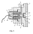
- Fig. 1 eine selbstkoppelnde, elektrisch überwachte, lösbare Verbindung zwischen einer Lichtleitfaser und einem Lasergerät;
- Fig. 2 eine Verbindung gemäß Fig. 1 mit zusätzlicher optischer Selbstjustierung mittels eines Temperaturfühlers;
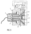
- Fig. 3 eine Verbindung gemäß Fig. 1 mit zusätzlicher optischer Selbstjustierung mittels Photoelementen.
- Bei dem in Fig. 1 dargestellten Ausführungsbeispiel wird die Strahlung 1 eines nicht näher dargestellten Lasergerätes auf eine Einkoppeloptik 2.1 gerichtet, welche in einer zylindrischen Öffnung 2.2 eines laserseitigen metallischen Koppelelementes 2 angeordnet ist. Das Koppelelement 2 ist mit dem Gehäuse 3 des Lasergerätes fest verbunden. In die zylindrische öffnung 2.2 wird ein paßgenauer metallischer Führungsstift 4.1 eines lichtleitfaserseitigen Koppelelementes 4 geschoben. Die Einstecktiefe wird durch einen Kragen 4.2 des Führungsstiftes 4.1 bestimmt, welcher im eingekoppelten Zustand plan auf einer entsprechenden Ringfläche 2.3 des Koppelelementes 2 aufliegt und einen guten Wärmeübergang gewährleistet. Gleichzeitig werden im eingekoppelten Zustand durch den Kragen 4.2 zwei elektrische Kontakte 5 und 6 kurzgeschlossen, wodurch eine elektrische Überwachung der Steckverbindung möglich ist. In einer zentralen axialen Bohrung 4.3 des Führungsstiftes 4.1 ist eine Lichtleitfaser 7 bis zum stirnseitigen Ende des Führungsstiftes hindurchgeführt. Bei zusammengesteckter Verbindung befindet sich die Frontfläche der Lichtleitfaser exakt im Brennpunkt 8 der Einkoppeloptik 2.1. Um dies zu gewährleisten, ist die Einkoppeloptik 2.1 in einer in das Koppelelement 2 einschraubbaren Fassung 2.4 axial verschiebbar.
- Zur Erzeugung einer axialen Zugkraft auf das Koppelelement 4 ist die zylindrische Bohrung 2.2 von einer Spule 2.5 umgeben, die über eine Leitung 2.6 mit Strom versorgt wird. Zur Erzeugung einer magnetischen Kraft muß der Führungsstift 4.1 aus einem ferromagnetischen Material bestehen; für das laserseitige Koppelelement ist dies nicht unbedingt erforderlich.Zur mechanischen Fixierung der Steckverbindung ist eine in dem Koppelelement 2 verankerte Überwurfmutter 2.7 vorgesehen, welche über ein Gewinde oder eine Bajonettverbindung eine mit dem Führungsstift 4.1 verbundene und als Schutzkappe für das Lichtleiterende dienende Hülse 4.8 mit dem Koppelelement 2 verriegelt.
- Das in Fig. 2 dargestellte Ausführungsbeispiel gleicht in seinen wesentlichen Bestandteilen demjenigen aus Fig. 1, jedoch ist zum Zwecke einer Selbstjustierung der Einkoppeloptik 2.1 diese in einer axial verschiebbaren Fassung 2.4 befestigt, welche durch einen elektrischen Antrieb 9, z.B. ein Elektromotor, bewegt wird. Die Steuerung des Antriebs erfolgt durch einen Temperaturfühler, der in dem Führungsstift 4.1 des Koppelelementes 4 thermisch leitend befestigt ist. Das Temperatursignal wird in einer für den Fachmann geläufigen und daher nicht näher ausgeführten Schaltung verarbeitet, welche den Antrieb auf eine Position steuert, bei welchem die Temperatur im Führungsstift ein Minimum erreicht. In diesem Fall kann davon ausgegangen werden, daß eine optimale Einkopplung des Laserlichtes in den Lichtleiter stattfindet.
- Das in Fig. 3 dargestellte Ausführungsbeispiel geht wiederum von einer Verbindung gemäß Fig. 1 aus, wobei zur optischen Selbstjustierung vier Photoelemente vorgesehen sind, welche unter einem Winkel von etwa 45° auf vier Bereiche der Stirnfläche des Führungsstiftes 4.1 gerichtet sind, welche in etwa den Quadranten der kreisförmigen Stirnfläche entsprechen. Von den vier Photoelementen sind lediglich zwei (13.1 und 13.3) in der Schnittzeichnung zu erkennen. Die Photoelemente erfassen die von der Stirnfläche des Führungsstiftes nicht eingekoppelte und somit reflektierte Laserstrahlung und geben intensitätsabhängige Signale an eine Elektronik 12. Diese steuert zwei elektrische Stell- glieder 10 und 11, mit denen die Einkoppeloptik 2.1 in axialer und radialer Richtung verschoben wird, bis die reflektierte Laserstrahlung in allen vier Photoelemen- ten ein gleiches Signal liefert und die reflektierte Strahlung insgesamt ein Minimum ist.
- Die Stirnfläche des Führungsstiftes 4.1 bildet zusammen mit der Wandung 2.2 und einer O-Ring-gedichteten transparenten Scheibe 18 eine im wesentlichen luftdichte Kammer 17, welche über eine Leitung 16 mit einem Unter- bzw. Überdruckerzeuger verbunden ist. Dadurch ist die Verbindung nicht nur selbststeckend, sondern auch noch selbsttrennend.
- Sollte in dem Koppelelement 2 kein Platz mehr für die Unterbringung von Photoelementen sein, so könnte die rückgestreute Laserstrahlung auch mittels eines im Strahlengang befindlichen Umlenkspiegels ausgekoppelt und gemessen werden.
- Auch ist es selbstverständlich möglich, auf die elektrischen Stellglieder zu verzichten und die Einstellung der Einkoppeloptik aufgrund der angezeigten Meßwerte per Hand vorzunehmen.
Claims (7)
Priority Applications (1)
| Application Number | Priority Date | Filing Date | Title |
|---|---|---|---|
| AT85114123T ATE37103T1 (de) | 1984-12-08 | 1985-11-06 | Loesbare verbindung zwischen einer lichtleitfaser und einem lasergeraet. |
Applications Claiming Priority (2)
| Application Number | Priority Date | Filing Date | Title |
|---|---|---|---|
| DE3444823 | 1984-12-08 | ||
| DE3444823A DE3444823C2 (de) | 1984-12-08 | 1984-12-08 | Lösbare Verbindung zwischen einer Lichtleitfaser und einem Lasergerät |
Publications (3)
| Publication Number | Publication Date |
|---|---|
| EP0184668A2 true EP0184668A2 (de) | 1986-06-18 |
| EP0184668A3 EP0184668A3 (en) | 1986-12-10 |
| EP0184668B1 EP0184668B1 (de) | 1988-09-07 |
Family
ID=6252244
Family Applications (1)
| Application Number | Title | Priority Date | Filing Date |
|---|---|---|---|
| EP85114123A Expired EP0184668B1 (de) | 1984-12-08 | 1985-11-06 | Lösbare Verbindung zwischen einer Lichtleitfaser und einem Lasergerät |
Country Status (5)
| Country | Link |
|---|---|
| US (1) | US4775211A (de) |
| EP (1) | EP0184668B1 (de) |
| JP (1) | JPS61141351A (de) |
| AT (1) | ATE37103T1 (de) |
| DE (2) | DE3444823C2 (de) |
Cited By (1)
| Publication number | Priority date | Publication date | Assignee | Title |
|---|---|---|---|---|
| FR2637741A1 (fr) * | 1988-08-11 | 1990-04-13 | Morita Mfg | Dispositif a rayonnement laser a angle de rayonnement variable |
Families Citing this family (18)
| Publication number | Priority date | Publication date | Assignee | Title |
|---|---|---|---|---|
| WO1988000072A1 (fr) * | 1986-06-30 | 1988-01-14 | Medical Laser Research Co., Ltd. | Appareil therapeutique a laser a semiconducteur |
| DE8708660U1 (de) * | 1987-06-22 | 1987-10-15 | Schott Glaswerke, 6500 Mainz | Lichtleiter-Einkopplungsvorrichtung für einen Laserkopf |
| JPH01173004A (ja) * | 1987-12-28 | 1989-07-07 | Takashi Mori | 光導体ケーブルの受光端をレンズの焦点に合わせるための機構 |
| US4840450A (en) * | 1988-02-03 | 1989-06-20 | General Electric Company | Apparatus and method for optical fiber end positioning for laser injection |
| GB8807385D0 (en) * | 1988-03-29 | 1988-05-05 | British Telecomm | Semiconductor device assembly |
| DE3830517C1 (en) * | 1988-09-08 | 1990-01-18 | Messerschmitt-Boelkow-Blohm Gmbh, 8012 Ottobrunn, De | Light guide (pipe) coupling for a medical laser unit |
| DE9013325U1 (de) * | 1990-09-20 | 1992-02-06 | INTERATOM GmbH, 5060 Bergisch Gladbach | Küvette mit integrierten Lichtleiterfasern |
| US5231686A (en) * | 1992-07-17 | 1993-07-27 | Honeywell Inc. | Optical connector configured to facilitate active alignment of a photoelectric device with an optical fiber |
| DE19829988B4 (de) * | 1998-07-04 | 2006-08-10 | Carl Zeiss Jena Gmbh | Einrichtung zur Ausrichtung mindestens einer Lichtleitfaser in einem Mikroskop |
| US6607304B1 (en) | 2000-10-04 | 2003-08-19 | Jds Uniphase Inc. | Magnetic clamp for holding ferromagnetic elements during connection thereof |
| WO2002052322A1 (en) * | 2000-12-22 | 2002-07-04 | Asah Medico A/S | An optical fibre connector assembly |
| US7485116B2 (en) * | 2004-09-22 | 2009-02-03 | Densen Cao | Laser systems, with a fiber storage and dispensing unit, useful in medicine and dentistry |
| DE102005018845B4 (de) * | 2005-04-22 | 2007-05-16 | Dirk Gansert | Miniaturisierte und multifunktionale optosensorische Meß- und Regelschleuse |
| DE102005022608B3 (de) * | 2005-05-11 | 2007-01-11 | Karl Storz Gmbh & Co. Kg | Lichtsystem zur photodynamischen Diagnose und/oder Therapie |
| WO2008103519A2 (en) * | 2007-02-21 | 2008-08-28 | Cao Group, Inc. | Modular laser systems |
| JP5856167B2 (ja) * | 2010-08-10 | 2016-02-09 | ペイシェント・ポケット・エルエルシーPatient Pocket,Llc | レーザー光ファイバー保管 |
| US10989855B2 (en) | 2017-11-09 | 2021-04-27 | AGM Automotive, LLC | Illumination device for projecting light in a predetermined illumination pattern on a surface |
| WO2019224601A2 (en) * | 2018-05-24 | 2019-11-28 | Panasonic intellectual property Management co., Ltd | Exchangeable laser resonator modules with angular adjustment |
Family Cites Families (13)
| Publication number | Priority date | Publication date | Assignee | Title |
|---|---|---|---|---|
| FR2356167A1 (fr) * | 1976-06-21 | 1978-01-20 | Labo Electronique Physique | Connecteur de fibres optiques a un emetteur ou un recepteur d'energie lumineuse |
| JPS5360651A (en) * | 1976-11-12 | 1978-05-31 | Hitachi Ltd | Semiconductor laser with optical fibers |
| US4307934A (en) * | 1978-05-08 | 1981-12-29 | General Dynamics, Pomona Division | Packaged fiber optic modules |
| DE2918024C2 (de) * | 1979-05-04 | 1981-07-30 | Licentia Patent-Verwaltungs-Gmbh, 6000 Frankfurt | Justiereinrichtung für eine Lichtleitfaserverbindung mit Linsenkopplung |
| JPS616888Y2 (de) * | 1980-01-14 | 1986-03-03 | ||
| JPS56145017U (de) * | 1980-04-01 | 1981-11-02 | ||
| GB2076993B (en) * | 1980-05-31 | 1983-11-09 | Barr & Stroud Ltd | Optical fibre light guides for use with lasers |
| JPS576818A (en) | 1980-06-16 | 1982-01-13 | Matsushita Electric Ind Co Ltd | Optical connector |
| JPS6238647Y2 (de) * | 1980-12-15 | 1987-10-02 | ||
| JPS6051900B2 (ja) * | 1981-05-28 | 1985-11-16 | 長田電機工業株式会社 | 歯科医療用レ−ザ−ハンドピ−ス |
| JPS5878111A (ja) * | 1981-11-04 | 1983-05-11 | Sumitomo Electric Ind Ltd | 複芯コネクタ |
| JPS58183177A (ja) * | 1982-04-19 | 1983-10-26 | 株式会社東芝 | 治療用レ−ザ装置 |
| JPH05950A (ja) | 1991-06-20 | 1993-01-08 | Yoshitomi Pharmaceut Ind Ltd | 利尿剤 |
-
1984
- 1984-12-08 DE DE3444823A patent/DE3444823C2/de not_active Expired
-
1985
- 1985-11-06 DE DE8585114123T patent/DE3564868D1/de not_active Expired
- 1985-11-06 EP EP85114123A patent/EP0184668B1/de not_active Expired
- 1985-11-06 AT AT85114123T patent/ATE37103T1/de not_active IP Right Cessation
- 1985-12-06 JP JP60273549A patent/JPS61141351A/ja active Granted
- 1985-12-09 US US06/806,767 patent/US4775211A/en not_active Expired - Fee Related
Cited By (1)
| Publication number | Priority date | Publication date | Assignee | Title |
|---|---|---|---|---|
| FR2637741A1 (fr) * | 1988-08-11 | 1990-04-13 | Morita Mfg | Dispositif a rayonnement laser a angle de rayonnement variable |
Also Published As
| Publication number | Publication date |
|---|---|
| US4775211A (en) | 1988-10-04 |
| DE3444823C2 (de) | 1986-10-02 |
| DE3564868D1 (en) | 1988-10-13 |
| JPH0560385B2 (de) | 1993-09-02 |
| ATE37103T1 (de) | 1988-09-15 |
| EP0184668B1 (de) | 1988-09-07 |
| EP0184668A3 (en) | 1986-12-10 |
| JPS61141351A (ja) | 1986-06-28 |
| DE3444823A1 (de) | 1986-06-12 |
Similar Documents
| Publication | Publication Date | Title |
|---|---|---|
| EP0184668B1 (de) | Lösbare Verbindung zwischen einer Lichtleitfaser und einem Lasergerät | |
| DE69418241T2 (de) | Spannungsdetektionsapparat | |
| EP1430344B1 (de) | Steckverbinder für ein kombinationskabel | |
| DE2752783C2 (de) | Gerät zum Erfassen und Verarbeiten von elektrischen Signalen | |
| DE2623389B2 (de) | Vorrichtung zur Verbindung einer Laserdiode mit einem Lichtleiter | |
| DE69109317T2 (de) | Verfahren zur Herstellung eines optischen Kopplers. | |
| DE3822312A1 (de) | Halbleiter-lasermodul vom dual-in-line-gehaeusetyp | |
| DE102009042529A1 (de) | Laserbearbeitungskopf mit einer Fokuslagenjustageeinheit sowie ein System und ein Verfahren zum Justieren einer Fokuslage eines Laserstrahls | |
| DE10021564A1 (de) | Oben-Kontakt-VCSEL mit Monitor | |
| DE112015001857T5 (de) | Glasfaserscanner, Beleuchtungsvorrichtung und Beobachtungsgerät | |
| EP0992823B1 (de) | Verfahren zur Justage eines optoelektronischen Bauelements | |
| EP0380775B1 (de) | Adapter für einen Lichtleiter | |
| CH443507A (de) | Gerät zum Steuern der Betriebsparameter eines Ladungsträgerstrahles und der Lage desselben relativ zu einem zu bearbeitenden Werkstück | |
| DE3932458C2 (de) | Verfahren zum gegenseitigen Ausrichten einer optischen Energiequelle und eines Lichtleiters sowie Vorrichtung zur Durchführung des Verfahrens | |
| WO2002040098B1 (de) | Vorrichtung zur akupunktur mittels laserstrahlung | |
| DE3307669C2 (de) | ||
| DE4017286A1 (de) | Verfahren und vorrichtung zum loeten und entloeten | |
| DE69424685T2 (de) | Mikroausrichtevorrichtung | |
| DE69621803T2 (de) | Elektronenstrahlerzeugende Vorrichtung | |
| DE4035404C2 (de) | ||
| EP0134425A2 (de) | Lichtwellenleitersteckvorrichtung | |
| EP0229743B1 (de) | Einrichtng mit einer Kunststoff-Schweissmuffe und einem Anschlusskopf | |
| DE60313574T2 (de) | Optische Strahlteiler-Vorrichtung mit deformierbarer Verbindung zwischen zwei Strahlteilern | |
| WO2005078383A1 (de) | Konfokaler abstandssensor | |
| DE2849543A1 (de) | Verbindungselement fuer lichtleiter |
Legal Events
| Date | Code | Title | Description |
|---|---|---|---|
| PUAI | Public reference made under article 153(3) epc to a published international application that has entered the european phase |
Free format text: ORIGINAL CODE: 0009012 |
|
| AK | Designated contracting states |
Kind code of ref document: A2 Designated state(s): AT BE CH DE FR GB IT LI LU NL SE |
|
| PUAL | Search report despatched |
Free format text: ORIGINAL CODE: 0009013 |
|
| AK | Designated contracting states |
Kind code of ref document: A3 Designated state(s): AT BE CH DE FR GB IT LI LU NL SE |
|
| 17P | Request for examination filed |
Effective date: 19870311 |
|
| 17Q | First examination report despatched |
Effective date: 19870722 |
|
| GRAA | (expected) grant |
Free format text: ORIGINAL CODE: 0009210 |
|
| AK | Designated contracting states |
Kind code of ref document: B1 Designated state(s): AT BE CH DE FR GB IT LI LU NL SE |
|
| PG25 | Lapsed in a contracting state [announced via postgrant information from national office to epo] |
Ref country code: SE Effective date: 19880907 Ref country code: NL Effective date: 19880907 Ref country code: BE Effective date: 19880907 |
|
| REF | Corresponds to: |
Ref document number: 37103 Country of ref document: AT Date of ref document: 19880915 Kind code of ref document: T |
|
| REF | Corresponds to: |
Ref document number: 3564868 Country of ref document: DE Date of ref document: 19881013 |
|
| ET | Fr: translation filed | ||
| PG25 | Lapsed in a contracting state [announced via postgrant information from national office to epo] |
Ref country code: AT Effective date: 19881106 |
|
| PG25 | Lapsed in a contracting state [announced via postgrant information from national office to epo] |
Ref country code: LU Free format text: LAPSE BECAUSE OF NON-PAYMENT OF DUE FEES Effective date: 19881130 Ref country code: LI Effective date: 19881130 Ref country code: CH Effective date: 19881130 |
|
| ITF | It: translation for a ep patent filed | ||
| GBT | Gb: translation of ep patent filed (gb section 77(6)(a)/1977) | ||
| NLV1 | Nl: lapsed or annulled due to failure to fulfill the requirements of art. 29p and 29m of the patents act | ||
| PLBI | Opposition filed |
Free format text: ORIGINAL CODE: 0009260 |
|
| 26 | Opposition filed |
Opponent name: OLYMPUS OPTICAL COMPANY LTD. Effective date: 19890602 |
|
| REG | Reference to a national code |
Ref country code: CH Ref legal event code: PL |
|
| ITTA | It: last paid annual fee | ||
| PLBN | Opposition rejected |
Free format text: ORIGINAL CODE: 0009273 |
|
| STAA | Information on the status of an ep patent application or granted ep patent |
Free format text: STATUS: OPPOSITION REJECTED |
|
| 27O | Opposition rejected |
Effective date: 19920522 |
|
| REG | Reference to a national code |
Ref country code: GB Ref legal event code: 732E |
|
| REG | Reference to a national code |
Ref country code: FR Ref legal event code: TP |
|
| PGFP | Annual fee paid to national office [announced via postgrant information from national office to epo] |
Ref country code: GB Payment date: 19961021 Year of fee payment: 12 |
|
| PGFP | Annual fee paid to national office [announced via postgrant information from national office to epo] |
Ref country code: FR Payment date: 19961114 Year of fee payment: 12 |
|
| PGFP | Annual fee paid to national office [announced via postgrant information from national office to epo] |
Ref country code: DE Payment date: 19961121 Year of fee payment: 12 |
|
| PG25 | Lapsed in a contracting state [announced via postgrant information from national office to epo] |
Ref country code: GB Free format text: LAPSE BECAUSE OF NON-PAYMENT OF DUE FEES Effective date: 19971106 |
|
| PG25 | Lapsed in a contracting state [announced via postgrant information from national office to epo] |
Ref country code: FR Free format text: THE PATENT HAS BEEN ANNULLED BY A DECISION OF A NATIONAL AUTHORITY Effective date: 19971130 |
|
| GBPC | Gb: european patent ceased through non-payment of renewal fee |
Effective date: 19971106 |
|
| PG25 | Lapsed in a contracting state [announced via postgrant information from national office to epo] |
Ref country code: DE Free format text: LAPSE BECAUSE OF NON-PAYMENT OF DUE FEES Effective date: 19980801 |
|
| REG | Reference to a national code |
Ref country code: FR Ref legal event code: ST |