EP0184923B1 - Système de communication à bande latérale unique - Google Patents
Système de communication à bande latérale unique Download PDFInfo
- Publication number
- EP0184923B1 EP0184923B1 EP85308784A EP85308784A EP0184923B1 EP 0184923 B1 EP0184923 B1 EP 0184923B1 EP 85308784 A EP85308784 A EP 85308784A EP 85308784 A EP85308784 A EP 85308784A EP 0184923 B1 EP0184923 B1 EP 0184923B1
- Authority
- EP
- European Patent Office
- Prior art keywords
- signal
- ssb
- output
- communication system
- multiplier
- Prior art date
- Legal status (The legal status is an assumption and is not a legal conclusion. Google has not performed a legal analysis and makes no representation as to the accuracy of the status listed.)
- Expired
Links
Images


Classifications
-
- H—ELECTRICITY
- H04—ELECTRIC COMMUNICATION TECHNIQUE
- H04B—TRANSMISSION
- H04B1/00—Details of transmission systems, not covered by a single one of groups H04B3/00 - H04B13/00; Details of transmission systems not characterised by the medium used for transmission
- H04B1/62—Details of transmission systems, not covered by a single one of groups H04B3/00 - H04B13/00; Details of transmission systems not characterised by the medium used for transmission for providing a predistortion of the signal in the transmitter and corresponding correction in the receiver, e.g. for improving the signal/noise ratio
-
- H—ELECTRICITY
- H04—ELECTRIC COMMUNICATION TECHNIQUE
- H04B—TRANSMISSION
- H04B1/00—Details of transmission systems, not covered by a single one of groups H04B3/00 - H04B13/00; Details of transmission systems not characterised by the medium used for transmission
- H04B1/68—Details of transmission systems, not covered by a single one of groups H04B3/00 - H04B13/00; Details of transmission systems not characterised by the medium used for transmission for wholly or partially suppressing the carrier or one side band
Definitions
- This invention relates to a single-sideband (SSB) communication system and, more specifically, to apparatus for carrying out a demodulating process of SSB signals, in which a frequency detector and an amplitude limiter can be employed.
- SSB single-sideband
- SSB modulation Voice signals can be inherently transmitted in a bandwidth comparable to the information bandwidth. Therefore, an SSB modulation method is very useful from the view-point of a considerable saving of bandwidth.
- the information is contained in the signal envelope.
- AGC automatic gain control
- regeneration of the carrier is necessary for demodulation of the SSB signal. Carrier recovery is a cumbersome operation for mobile radios.
- US-A-3508155 relates to asynchronous demodulation of a full carrier SSB signal using only envelope properties.
- An object of the invention is to provide an SSB communication system in which the necessary radio-frequency bandwidth is comparable to the information bandwidth and in which an amplitude limiter in the receiver portion of the system can be safely used to remove amplitude degradations caused by fading. Besides removing amplitude degradations, the system of the invention provides for demodulation of SSB signals by the use of a frequency detector and an equalizer.
- a SSB communication system comprises a transmitter transmitting an SSB amplitude modulation signal composed of both a single sideband carrier suppressed signal and a carrier signal; and a receiver including an amplitude limiter which removes amplitude variations of the received SSB amplitude modulation signal, a demodulator connected to an output of said amplitude limiter to demodulate the SSB amplitude modulation signal, a lineariser to cancel out distortions contained in the demodulated signal, characterized in that the receiver further includes, an equalizer, which is composed of an integrator, connected to an output of said frequency detector to compensate a frequency response of a frequency-detected signal; in that the demodulator is a frequency detector; and in that the lineariser connected to an output of said equaliser comprises a Hilbert transformer providing a Hilbert transform of an input signal from said frequency detector, a multiplier providing a product of said Hilbert transformer output and the input signal, and a subtractor subtracting a second order product, derived
- an SSB communication system comprises a transmitter transmitting an SSB amplitude modulation signal composed of both a single sideband carrier suppressed signal and a carrier signal; and a receiver including an amplitude limiter which removes amplitude variations of the received SSB amplitude modulation signal, a demodulator connected to an output of said amplitude limiter to demodulate the SSB amplitude modulation signal, and a lineariser to cancel out distortions contained in the demodulated signal, characterized in that the demodulator is a frequency detector; in that the receiver further includes a - 6dB/octave response equalizer, connected to an output of said frequency detector to compensate a frequency response of a frequency-detected signal; and in that the lineariser connected to an output of said equaliser comprises a Hilbert transformer providing a Hilbert transform of an input signal from said frequency detector, an adder and a subtractor providing a sum and difference between the input signal and the output of said Hilbert transformer
- an SSB communication system comprises a transmitter transmitting an SSB amplitude modulation signal composed of both a single sideband carrier suppressed signal and a carrier signal; and a receiver including an amplitude limiter which removes amplitude variation of the received SSB amplitude modulation signal, a demodulator connected to an output of said amplitude limiter to demodulate the SSB amplitude modulation signal, and a lineariser to cancel out distortions contained in the demodulated signal, characterized in that the demodulator comprises a frequency detector; in that the receiver further includes an equalizer, which is composed of an integrator, connected to an output of said frequency detector to compensate a frequency response of a frequency-detected signal; and in that the lineariser comprises a Hilbert transformer providing a Hilbert transform of an input signal, a first multiplier providing a product of the output of said Hilbert transfer and the input signal, a cuber providing a cube of the input signal, a second multiplier providing
- the principle of the present invention is based upon the fact that signals expressed only in real simple zeros can be fed into an amplitude limiter.
- an SSB signal modulated by a band-limited baseband signal is accompanied by a carrier, whose level is higher than that of the SSB signal, this SSB signal is called a full-carrier SSB.
- a frequency detector (frequency discriminator) performs the operation, Then, where the prime symbol implies differentiation.
- the system further comprises a receiving antenna 9, a down-converter 10 for converting the frequency from RF to IF (intermediate frequency), an IF amplifier 11, an amplitude limiter 12 for removing amplitude variations of a received SSB signal, a frequency detector 13, a frequency-response equaliser 14, a lineariser 15 for cancelling distortions contained in the demodulated signal, an AF (audio frequency) amplifier 16, and an output terminal 17, together forming a receiver portion 18 of the system.
- a receiving antenna 9 a down-converter 10 for converting the frequency from RF to IF (intermediate frequency)
- an IF amplifier 11 for converting the frequency from RF to IF (intermediate frequency
- an amplitude limiter 12 for removing amplitude variations of a received SSB signal
- a frequency detector 13 for removing amplitude variations of a received SSB signal
- a frequency detector 13 for removing amplitude variations of a received SSB signal
- a frequency detector 13 for
- voice signals in a frequency range of, for example 300Hz to 3.0kHz are provided from the signal source 1.
- the voice signals are fed to the SSB modulator 3, which is also fed with an IF carrier signal produced by a local oscillator 2.
- a single-sideband suppressed-carrier signal is generated at the output of the SSB modulator 3 by using, for example, the phasing method.
- the output of the SSB modulator 3 is fed to the adder 4, where it is combined with the carrier (the signal from the local oscillator 2).
- the output of the adder 4 feeds the up-converter 5 which converts the frequency to the RF region.
- the RF amplifier 6 amplifies the RF signal, which is radiated through the air by the transmitting antenna 7.
- the output of the amplitude limiter 12 is applied to the frequency detector 13 to provide demodulated voice signals which, in turn, feed the equaliser 14 which compensates the frequency response in the bandwidth of interest.
- the equaliser 14 which compensates the frequency response in the bandwidth of interest.
- the output of the equaliser 14 is fed to the lineariser 15 in order to cancel out distortion generated in the demodulation process.
- the output of the lineariser 15 is fed through the AF amplifier 16 to the output terminal 16.
- FIG. 2 is a block diagram of the lineariser 15, when the frequency detector 13 and the integrator 14a are employed.
- the lineariser comprises an input terminal 21, a Hilbert transformer 22, a multiplier 23, a delay circuit 24, a subtractor 25, and an output terminal 26.
- Figure 3 shows another form of the lineariser 15, which comprises an input terminal 31, a Hilbert transformer 32, a substractor 33, an adder 34, a multiplier 35, a delay circuit 36, an adder 37, an output terminal 38 and an attenuator 39 for halving the signal level.
- the lineariser depicted in Figure 3 is applicable when the frequency detector 13 is accompanied by a -6 dB/octave response equaliser 14b.
- the operation of the lineariser is governed by equation (4).
- the signal at the input terminal 31, which is the output of the frequency equaliser 14, is applied to the Hilbert transformer 32, the subtractor 33, the adder 34 and the delay circuit 36.
- the output of the Hilbert transformer 32 is applied to the subtractor 33 and the adder 34.
- the product signal which is derived from the multiplier 35 is m2(g(t)- g ⁇ (t))(g(t)+ g ⁇ (t)) + O(m3) .
- This signal is fed through the attenator 39 to the adder 37 where it is combined with the output of the delay circuit 36.
- the delay time should be adjusted in order to cancel out the second-order product of g(t).
- the delay circuit 36 is useful to compensate the total delay time arising from the Hilbert transformer 32, the subtractor 33, the adder 34 and the multiplier 35. Then the signal at the output of the adder 37 is mg(t) + O(m3) which is free from the second-order product of g(t).
- Figure 4 shows another form of the lineariser 15, which comprises an input terminal 41, a delay circuit 42, a Hilbert transformer 43, a cuber 44, multipliers 45 and 46, attenuators 47 and 48, a summation circuit 49 and an output terminal 50.
- the signal at the input terminal 41 which is the output of the frequency detector 13, is denoted by v1(t) as formulated in equation (3).
- the input signal is distributed to the delay circuit 42, the Hilbert transformer 43, the cuber 44 and the multiplier 45.
- the output of the Hilbert transformer is then v ⁇ 1(t), which feeds the multipliers 45 and 46.
- the signals of the output of the multipliers 45 and 46 are v1(t)v ⁇ 1(t) and v1(t)v ⁇ 12(t), respectively.
- the output of the multiplier 46 is connected to the attenuator 48, the attenuation factor of which is 1/2.
- the cuber 44 provides the cube of v1(t), and this is fed to the attenuator 47 which has an attenuation factor of 1/6.
- the signals derived from the delay circuit 42, the multiplier 45 and the attenuators 47 and 48 are gathered at the summation circuit 49, the rule of which, as shown in the drawing, is governed by equation (6).
- the delay time of the delay circuit 42 should be adjusted to cancel out the second and third order products of g(t). Then, the signal at the output terminal is m g ⁇ (t) + O(m4) which indicates that the residual distortion level is very small when m ⁇ 1.
- Figure 5 shows a modification of the present invention.
- the selective amplification circuit of the carrier component depicted in Figure 5 is required to regenerate a full-carrier SSB signal from the received signal.
- the circuit depicted in Figure 5 is inserted between the IF amplifier 11 and the amplitude limiter 12 shown in Figure 1.
- the circuit comprises an input terminal 51, a delay circuit 52, a bandpass filter 53, an IF amplifier 54, an adder 55 and an output terminal 56.
- the signal at the input terminal 51 which is the output of the IF amplifier 11, is fed to the delay circuit 52 and the bandpass filter 53.
- the carrier component whose frequency is converted to the IF region is extracted by the bandpass filter 53.
- the output of the bandpass filter 53 is amplified in the IF amplifier 54 up to a sufficiently high level to satisfy the condition of a full-carrier SSB signal.
- the signal at the output of the IF amplifier 54 is combined with the output of the delay circuit 52 at the adder 55. Then, the signal at the output terminal 56 can be safely introduced to the amplitude limiter 12.
- Figure 6 shows a modification of the present invention, where a modulating signal is pre-distorted in the transmitter portion of the system, so that the lineariser circuit depicted in Figures 2, 3 or 4 is not necessary in the receiver portion of the system.
- arctan[m g ⁇ (t)/(1 + mg(t))] m g ⁇ (t) (8) the signal demodulated by the frequency detector and the equaliser does not produce any distortion.
- the left hand side of equation (8) is the signal demodulated by the frequency detector and the equaliser, and the right hand side of equation (8) is the Hilbert transform of the original information signal sent by the transmitter.
- g(t) which is pre-distorted in keeping with the relation of equation (9)
- the detected signal always corresponds to the original information signal even though it is Hilbert-transformed.
- the product of the output of the adder 65 and the tangent function generator 63 is produced by the multiplier 66.
- the signal at the output of the multiplier 66 is fed back to the input of the tangent function generator 63.
- the output of the Hilbert transformer 67 then comprises the pre-distorted signal. This output is fed to the output terminal 68.
- a syllabic compandor is available to suppress harmful noises such as thermal noise, man-made noise and/or click noise.
- a compressor is introduced between the signal source 1 and the SSB modulator 3 shown in Figure 1.
- the compressor (not shown) compresses the signal level which is lower than a reference level. Then, the dynamic range between the highest and the lowest signal level is reduced.
- the compressed signal is fed to the SSB modulator 3 and is transmitted.
- an expandor (not shown) is introduced between the lineariser 15 and the AF amplifier 16 so that the received compressed signal is expanded. When noise is superimposed on the signal, it is reduced in the expansion process.
- the SNR signal-to-noise ratio
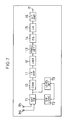
- FIG 7 shows a modification of the invention. Diversity systems provide the most promising scheme for elimination of the effects of fading.
- the reference numerals 10 to 17 represent the same integers as in Figure 1.
- the cicuit further comprises receiving antennas 9a and 9b, an antenna switch 71, a switch logic circuit 72 and a level detector 73.
- the instantaneous envelope of the signal received by the receiving antenna 9a is monitored by the level detector 73. If it falls below a predetermined threshold, the antenna switch 71 is activated by the switch logic circuit 72, so that it selects the second antenna, 9b. If the signal from the second antenna is above the threshold, switching ceases. If the signal in the second antenna is also subject to fading, we can revert to the first antenna.
- a signal in which amplitude fading is substantially eliminated is derived from the output of the antenna switch 71.
- a further modification of the present invention is the use of a smearing filter for improving the SNR of the detected signal.
- Smearing and desmearing filters (not shown) are placed before the modulator and after the demodulator, respectively. Both of these filters then operate on the information signal, and the filters are usually chosen to be complementary so that, in the ideal case, the net effect upon the information signal is merely a delay.
- the present invention possesses the following particular effects and is particularly applicable to use in mobile radio communication systems.
Landscapes
- Engineering & Computer Science (AREA)
- Computer Networks & Wireless Communication (AREA)
- Signal Processing (AREA)
- Reduction Or Emphasis Of Bandwidth Of Signals (AREA)
- Transmitters (AREA)
Claims (8)
- Système de communication à bande latérale simple (SSB) comportant un émetteur (8) émettant un signal modulateur d'amplitude SSB comptant à la fois un signal supprimé de porteur de bande latérale simple et un signal porteur; et un récepteur (18) muni d'un limiteur d'amplitude (12) éliminant les variations d'amplitude du signal ainsi reçu de modulation d'amplitude en bande latérale simple, un démodulateur (13) relié à une sortie dudit limiteur d'amplitude (12) pour démoduler le signal de modulation d'amplitude SSB, et un linéarisateur (15) pour éliminer les distorsions retenues par le signal démodulé, caractérisé en ce que le démodulateur est un détecteur de fréquence (13); en ce que le récepteur prévoit aussi un égaliseur (14) qui consiste d'un intégrateur, relié à une sortie dudit détecteur de fréquence (13) pour compenser la réponse de fréquence d'un signal de fréquence captée; et en ce que le linéarisateur (15) est relié à une sortie dudit égalisateur (14) et compte un transformateur Hilbert (22) apportant un signal d'entrée transformé Hilbert d'entrée dudit détecteur de fréquence (13), un multiplicateur (23) amenant le produit dudit signal d'entrée et sortie dudit transformateur Hilbert (22), et un soustracteur (25) qui retranche du signal d'entrée un produit de deuxième ordre dérivé dudit multiplicateur.
- Système de communication à bande latérale simple (SSB) ayant un émetteur (8) émettant un signal modulateur d'amplitude SSB prévoyant à la fois un signal supprimé de porteur de bande latérale simple et un signal porteur; et un récepteur (18) comportant un limiteur d'amplitude (12) éliminant les variations d'amplitude du signal ainsi reçu de modulation d'amplitude en bande latérale simple, un démodulateur (13) relié à une sortie dudit limiteur d'amplitude (12) pour démoduler le signal de modulation d'amplitude SSB et un linéarisateur (15) pour éliminer les distorsions retenues par le signal démodulé, caractérisé en ce que le démodulateur est un détecteur de fréquence (13); en ce que le récepteur (18) prévoit aussi un égalisateur (14) de réponse -6dB/octave relié à une sortie dudit détecteur de fréquence (13) compensateur de la réponse de fréquence d'un signal de fréquence captée; et en ce que le linéarisateur (15) relié à une sortie dudit égalisateur (14) compte un transformateur Hilbert (32) apportant un signal d'entrée transformé Hilbert d'entrée dudit détecteur de fréquence (13), un totalisateur (34) et un soustracteur (33) assurant le cumul et la différence respectivement entre le signal entrée et sortie dudit transformateur Hilbert (32), un multiplicateur apportant le produit des signaux de sortie desdits totalisateur et soustracteur, un atténuateur (39) divisant de moitié la sortie dudit multiplicateur et un totalisateur (37) apportant le cumul de sortie dudit atténuateur (39) et du signal d'entrée.
- Système de communication à bande latérale simple (SSB) ayant un émetteur (8) émettant un signal modulateur d'amplitude SSB à la fois composé du signal supprimé de porteur de bande latérale simple et d'un signal porteur; et un récepteur (18) avec limiteur d'amplitude (12) éliminant la variation d'amplitude du signal ainsi reçu de modulation d'amplitude en bande latérale simple, un démodulateur (13) relié à une sortie du limiteur d'amplitude (12) pour démoduler le signal de modulation d'amplitude SSB, et un linéarisateur (15) pour annuler les distorsions retenues par le signal démodulé caractérisé en ce que le démodulateur prévoit un détecteur de fréquence; en ce que le récepteur prévoit également un égalisateur (14) consistant d'un intégrateur, relié à une sortie dudit détecteur de fréquence (13) pour compenser la réponse de fréquence d'un signal de fréquence captée; et en ce que le linéarisateur (15) prévoit un transformateur Hilbert apportant un signal d'entrée transformé Hilbert, un premier multiplicateur (45) apportant un produit de sortie dudit transformateur Hilbert et du signal d'entrée, un dispositif de mise au cube (44) assurant le cube du signal d'entrée, un deuxième multiplicateur (46) apportant le produit des sorties de transformateur Hilbert (43) et du premier multiplicateur (45), un premier atténuateur (47) atténuant d'un facteur d'1/6 la sortie du dispositif de mise au cube, un deuxième atténuateur (48) atténuant une sortie dudit multiplicateur avec un facteur d'atténuation d'½, et un circuit (49) effectuant la totalisation du signal d'entrée, les sorties premier dudit multiplicateur (45) et les sorties desdits premier et deuxième atténuateurs (47,48).
- Système de communication à bande latérale simple (SSB) selon l'une ou l'autre des revendications précédentes dont le limitateur d'amplitude (12) est exploitépour extraire l'élément de phase du signal SSB ainsi reçu.
- Système de communication à bande latérale simple (SSB) selon l'une ou l'autre des revendications précédentes dont avant ledit limitateur d'amplitude (12) du récepteur (18), un amplificateur sélectif est relié pour l'amplification sélective d'un élément porteur lorsque le niveau du porteur est supérieur à celui du signal modulateur d'amplitude SSB, ledit amplificateur ayant un filtre passe-bande (53) pour l'extraction exclusive de l'élément porteur, une sortie du filtre passe-bande étant amplifiée par l'amplificateur(54), un circuit compensateur(52) effectuant la compensation du délai relevant à la fois desdits filtre passe-bande (53) et amplificateur(54) et un totalisateur(55) de cumul de sorties d'amplificateur et de circuit compensateur (52).
- Système de communication à bande latérale simple (SSB) selon l'une ou l'autre des revendications précédentes dont un système de communication de diversité est prévu en un seul au minimum desdits émetteur (8) et récepteur (18).
- Système de communication à bande latérale simple (SSB) selon l'une ou l'autre des revendications précédentes qui prévoit un compresseur/expandeur syllabique d'émetteur/récepteur de système de communication SSB, dont un compresseur pour ledit émetteur (8) et un expandeur pour ledit récepteur.
- Système de communication à bande latérale simple (SSB) selon l'une ou l'autre des revendications précédentes, qui prévoit un filtre de rémanence d'émetteur/récepteur de système de communication SSB, un filtre de rémanence audit émetteur (8) et un filtre éliminant la rémanence audit transmetteur (18).
Applications Claiming Priority (20)
| Application Number | Priority Date | Filing Date | Title |
|---|---|---|---|
| JP25935484A JPS61137431A (ja) | 1984-12-10 | 1984-12-10 | Ssb変復調方式 |
| JP259354/84 | 1984-12-10 | ||
| JP1261885A JPH0622290B2 (ja) | 1985-01-28 | 1985-01-28 | Ssb変復調方式 |
| JP12618/85 | 1985-01-28 | ||
| JP23646/85 | 1985-02-12 | ||
| JP2364685A JPH0740642B2 (ja) | 1985-02-12 | 1985-02-12 | Ssb復調回路 |
| JP82530/85 | 1985-04-19 | ||
| JP8253185A JPH0682985B2 (ja) | 1985-04-19 | 1985-04-19 | Ssb変調方式 |
| JP8253085A JPH0752808B2 (ja) | 1985-04-19 | 1985-04-19 | Ssb変復調方式 |
| JP82531/85 | 1985-04-19 | ||
| JP10943885A JPH0754916B2 (ja) | 1985-05-23 | 1985-05-23 | Ssb通信方式 |
| JP109438/85 | 1985-05-23 | ||
| JP116528/85 | 1985-05-31 | ||
| JP60116528A JPS61276431A (ja) | 1985-05-31 | 1985-05-31 | Ssb通信方式 |
| JP134213/85 | 1985-06-21 | ||
| JP13421385A JPH0746784B2 (ja) | 1985-06-21 | 1985-06-21 | Ssb通信方式 |
| JP136095/85 | 1985-06-24 | ||
| JP60136095A JPS61295726A (ja) | 1985-06-24 | 1985-06-24 | Ssb通信方式 |
| JP236449/85 | 1985-10-24 | ||
| JP23644985A JPH0740643B2 (ja) | 1985-10-24 | 1985-10-24 | 復調歪除去回路 |
Publications (3)
| Publication Number | Publication Date |
|---|---|
| EP0184923A2 EP0184923A2 (fr) | 1986-06-18 |
| EP0184923A3 EP0184923A3 (en) | 1988-06-22 |
| EP0184923B1 true EP0184923B1 (fr) | 1992-03-04 |
Family
ID=27579622
Family Applications (1)
| Application Number | Title | Priority Date | Filing Date |
|---|---|---|---|
| EP85308784A Expired EP0184923B1 (fr) | 1984-12-10 | 1985-12-03 | Système de communication à bande latérale unique |
Country Status (3)
| Country | Link |
|---|---|
| US (1) | US4803739A (fr) |
| EP (1) | EP0184923B1 (fr) |
| DE (1) | DE3585502D1 (fr) |
Families Citing this family (15)
| Publication number | Priority date | Publication date | Assignee | Title |
|---|---|---|---|---|
| SE464437B (sv) * | 1989-08-25 | 1991-04-22 | Ericsson Telefon Ab L M | Metod i en mogilradiomottagare foer att reducera mottagarens effektbehov |
| EP0684703B1 (fr) * | 1993-02-05 | 2001-09-05 | Nippon Telegraph And Telephone Corporation | Circuit d'elimination du bruit mf aleatoire |
| US6049720A (en) * | 1996-04-12 | 2000-04-11 | Transcrypt International / E.F. Johnson Company | Link delay calculation and compensation system |
| US5991309A (en) * | 1996-04-12 | 1999-11-23 | E.F. Johnson Company | Bandwidth management system for a remote repeater network |
| WO1997039541A1 (fr) * | 1996-04-12 | 1997-10-23 | E.F. Johnson Company | Systeme de commande d'emission utilisant la signalisation multifrequence |
| US5896560A (en) * | 1996-04-12 | 1999-04-20 | Transcrypt International/E. F. Johnson Company | Transmit control system using in-band tone signalling |
| US5764704A (en) * | 1996-06-17 | 1998-06-09 | Symmetricom, Inc. | DSP implementation of a cellular base station receiver |
| JP3601943B2 (ja) * | 1997-07-17 | 2004-12-15 | 富士通株式会社 | 無線catv映像信号伝送システム |
| IT1313792B1 (it) * | 1999-10-18 | 2002-09-23 | M B Internat S R L | Procedimento di generazione di un segnale modulato in frequenza, conricevibilita' migliorata da parte di una radioricevente |
| WO2001052442A1 (fr) * | 2000-01-10 | 2001-07-19 | Airnet Communications Corporation | Procede et appareil destine a l'egalisation de niveaux d'emission et de reception dans un systeme d'emission a bande large |
| US7042959B2 (en) * | 2002-02-20 | 2006-05-09 | Thomson Licensing | DSP-based variable aperture code generation technique |
| EP1640732B1 (fr) * | 2004-09-27 | 2008-01-02 | Rohde & Schwarz GmbH & Co. KG | Procedé et dispositif d'analyse spectrale par transformation-zéro avec transformée de Hilbert |
| US9647722B2 (en) * | 2013-03-15 | 2017-05-09 | Dockon Ag | Adaptive line equalizer for improving data communication over less than perfect power lines or transmission lines |
| CN106249076B (zh) * | 2016-07-22 | 2019-10-11 | 国家电网公司 | 受谐波负载影响下的配电变压器状态检测方法及系统 |
| CN110445734B (zh) * | 2018-05-03 | 2022-03-18 | 展讯通信(上海)有限公司 | 一种频偏估计方法及装置、存储介质、终端 |
Family Cites Families (10)
| Publication number | Priority date | Publication date | Assignee | Title |
|---|---|---|---|---|
| US2717956A (en) * | 1952-11-29 | 1955-09-13 | Bell Telephone Labor Inc | Reduction of quadrature distortion |
| NL191812A (fr) * | 1954-10-25 | |||
| US2989622A (en) * | 1958-12-29 | 1961-06-20 | Bell Telephone Labor Inc | Hybrid sideband frequency modulation system |
| US3508155A (en) * | 1965-07-26 | 1970-04-21 | Research Corp | Asynchronous single sideband radio reception systems |
| US3800131A (en) * | 1972-03-27 | 1974-03-26 | North American Rockwell | Hilbert transformer |
| US3984778A (en) * | 1974-11-13 | 1976-10-05 | Rixon Inc. | Carrier recovery scheme for a SSB-SC signal |
| US4064361A (en) * | 1975-12-31 | 1977-12-20 | Bell Telephone Laboratories, Incorporated | Correlative timing recovery in digital data transmission systems |
| FR2445079A1 (fr) * | 1978-12-20 | 1980-07-18 | Ibm France | Procede et dispositif pour detecter une sequence pseudo-aleatoire de changements de phase de 0o et 180o de la porteuse dans un recepteur de donnees |
| US4525862A (en) * | 1980-07-02 | 1985-06-25 | Motorola, Inc. | Transform modulation system |
| US4561111A (en) * | 1984-08-06 | 1985-12-24 | Rockwell International Corporation | Method of predistorting a single sideband system |
-
1985
- 1985-12-03 DE DE8585308784T patent/DE3585502D1/de not_active Expired - Lifetime
- 1985-12-03 EP EP85308784A patent/EP0184923B1/fr not_active Expired
- 1985-12-09 US US06/806,991 patent/US4803739A/en not_active Expired - Lifetime
Also Published As
| Publication number | Publication date |
|---|---|
| EP0184923A3 (en) | 1988-06-22 |
| DE3585502D1 (de) | 1992-04-09 |
| EP0184923A2 (fr) | 1986-06-18 |
| US4803739A (en) | 1989-02-07 |
Similar Documents
| Publication | Publication Date | Title |
|---|---|---|
| EP0184923B1 (fr) | Système de communication à bande latérale unique | |
| RU2225070C2 (ru) | Способ и устройство для снижения частотно-модулированных помех в системе цифрового звукового радиовещания внутриполосного канального типа | |
| USRE38603E1 (en) | Data transmitter and receiver of a spread spectrum communication system using a pilot channel | |
| US4523311A (en) | Simultaneous transmission of speech and data over an analog channel | |
| US5678198A (en) | System for controlling signal level at both ends of a transmission link, based upon a detected value | |
| Voelcker | Demodulation of single-sideband signals via envelope detection | |
| KR20000052914A (ko) | 전송방법 및 그 방법의 실행을 위한 장치 | |
| JP4489931B2 (ja) | 地上デジタルtv放送伝送方法及び地上デジタルtv放送システム | |
| US5095539A (en) | System and method of control tone amplitude modulation in a linked compression-expansion (Lincomplex) system | |
| US7254122B2 (en) | Apparatus and method for generating pilot beacon signal in base stations of CDMA system | |
| Bateman et al. | Speech and data communications over 942 MHz TAB and TTIB single sideband mobile radio systems incorporating feed-forward signal regeneration | |
| US4290144A (en) | Radio communications systems | |
| US7250541B2 (en) | Method for suppressing narrowband noise in a wideband communication system | |
| US5241538A (en) | Transmission apparatus | |
| Daikoku et al. | A real zero SSB transceiver for land mobile radio: A simple method of demodulating SSB signals without an envelope | |
| JP2743868B2 (ja) | Fdd方式の送信機 | |
| JP3514965B2 (ja) | 受信装置 | |
| US11785561B2 (en) | Digital channelizer with predistorter, high-power amplifier, and beamforming | |
| JP3804093B2 (ja) | 受信装置 | |
| Daikoku et al. | Experiments on real zero SSB transceiver demodulation of SSB signal without envelope | |
| Ikwuazom et al. | Simulation Analysis of Information Transmitting Mechanism Based on Amplitude Modulation Technique | |
| JPH0611125B2 (ja) | 同一周波数中継方式 | |
| JPH06152565A (ja) | コヒーレント光伝送装置 | |
| JP2595751B2 (ja) | 無線送受信機 | |
| JPH03254236A (ja) | マイクロ波多重無線送信装置 |
Legal Events
| Date | Code | Title | Description |
|---|---|---|---|
| PUAI | Public reference made under article 153(3) epc to a published international application that has entered the european phase |
Free format text: ORIGINAL CODE: 0009012 |
|
| 17P | Request for examination filed |
Effective date: 19851216 |
|
| AK | Designated contracting states |
Kind code of ref document: A2 Designated state(s): DE GB NL SE |
|
| PUAL | Search report despatched |
Free format text: ORIGINAL CODE: 0009013 |
|
| AK | Designated contracting states |
Kind code of ref document: A3 Designated state(s): DE GB NL SE |
|
| 17Q | First examination report despatched |
Effective date: 19900913 |
|
| GRAA | (expected) grant |
Free format text: ORIGINAL CODE: 0009210 |
|
| AK | Designated contracting states |
Kind code of ref document: B1 Designated state(s): DE GB NL SE |
|
| REF | Corresponds to: |
Ref document number: 3585502 Country of ref document: DE Date of ref document: 19920409 |
|
| PLBE | No opposition filed within time limit |
Free format text: ORIGINAL CODE: 0009261 |
|
| STAA | Information on the status of an ep patent application or granted ep patent |
Free format text: STATUS: NO OPPOSITION FILED WITHIN TIME LIMIT |
|
| 26N | No opposition filed | ||
| EAL | Se: european patent in force in sweden |
Ref document number: 85308784.9 |
|
| REG | Reference to a national code |
Ref country code: GB Ref legal event code: IF02 |
|
| PGFP | Annual fee paid to national office [announced via postgrant information from national office to epo] |
Ref country code: DE Payment date: 20041125 Year of fee payment: 20 |
|
| PGFP | Annual fee paid to national office [announced via postgrant information from national office to epo] |
Ref country code: GB Payment date: 20041201 Year of fee payment: 20 |
|
| PGFP | Annual fee paid to national office [announced via postgrant information from national office to epo] |
Ref country code: NL Payment date: 20041205 Year of fee payment: 20 |
|
| PGFP | Annual fee paid to national office [announced via postgrant information from national office to epo] |
Ref country code: SE Payment date: 20041206 Year of fee payment: 20 |
|
| PG25 | Lapsed in a contracting state [announced via postgrant information from national office to epo] |
Ref country code: GB Free format text: LAPSE BECAUSE OF EXPIRATION OF PROTECTION Effective date: 20051202 |
|
| PG25 | Lapsed in a contracting state [announced via postgrant information from national office to epo] |
Ref country code: NL Free format text: LAPSE BECAUSE OF EXPIRATION OF PROTECTION Effective date: 20051203 |
|
| REG | Reference to a national code |
Ref country code: GB Ref legal event code: PE20 |
|
| NLV7 | Nl: ceased due to reaching the maximum lifetime of a patent |
Effective date: 20051203 |
|
| EUG | Se: european patent has lapsed |