EP0185172A2 - Bande isolante d'extrémité - Google Patents
Bande isolante d'extrémité Download PDFInfo
- Publication number
- EP0185172A2 EP0185172A2 EP85113593A EP85113593A EP0185172A2 EP 0185172 A2 EP0185172 A2 EP 0185172A2 EP 85113593 A EP85113593 A EP 85113593A EP 85113593 A EP85113593 A EP 85113593A EP 0185172 A2 EP0185172 A2 EP 0185172A2
- Authority
- EP
- European Patent Office
- Prior art keywords
- edge insulation
- insulation strip
- foam
- edge
- surface material
- Prior art date
- Legal status (The legal status is an assumption and is not a legal conclusion. Google has not performed a legal analysis and makes no representation as to the accuracy of the status listed.)
- Withdrawn
Links
Images
Classifications
-
- E—FIXED CONSTRUCTIONS
- E04—BUILDING
- E04B—GENERAL BUILDING CONSTRUCTIONS; WALLS, e.g. PARTITIONS; ROOFS; FLOORS; CEILINGS; INSULATION OR OTHER PROTECTION OF BUILDINGS
- E04B2/00—Walls, e.g. partitions, for buildings; Wall construction with regard to insulation; Connections specially adapted to walls
- E04B2/74—Removable non-load-bearing partitions; Partitions with a free upper edge
- E04B2/82—Removable non-load-bearing partitions; Partitions with a free upper edge characterised by the manner in which edges are connected to the building; Means therefor; Special details of easily-removable partitions as far as related to the connection with other parts of the building
- E04B2/825—Removable non-load-bearing partitions; Partitions with a free upper edge characterised by the manner in which edges are connected to the building; Means therefor; Special details of easily-removable partitions as far as related to the connection with other parts of the building the connection between the floor and the ceiling being achieved without any restraining forces acting in the plane of the partition
Definitions
- the invention relates to an edge insulation strip according to the preamble of claim 1.
- Such edge insulation strips made of a sound-absorbing and resilient material are arranged on the front connection surfaces of non-load-bearing partition walls , in particular of so-called plasterboard, in such a way that the partition wall has no direct connection to the adjoining side wall, the adjoining floor or the adjoining ceiling. This prevents sound transmission at the edges of the partition between the two rooms separated from the partition.
- the soundproofing material that can be used for this is elastic and therefore largely unsuitable for power transmission. Rather, it also serves to absorb expansion in addition to sound insulation. This is necessary above all on the ceiling-side connection surface of the partition wall, because larger cantilevered ceilings can increasingly sink towards the center of the room.
- the edge insulation strips known for this purpose generally have a width corresponding to the partition wall thickness; they are first on the floor, on the side wall or on the ceiling, e.g. by gluing. Then the partition is pulled up and grouted with mortar or plaster at its front connection surfaces to the adjacent masonry in such a way that a flat connection to the support / connection surface of the associated edge insulation strip occurs.
- This edge grouting is very labor-intensive and difficult because it must be avoided that a non-positive sound bridge made of joint material is created between the intermediate wall and the wall, floor or ceiling surface adjoining it.
- the plaster or screed has a non-positive connection with the material of the intermediate wall during subsequent plastering of the connecting wall adjoining the intermediate wall. To avoid such sound bridges, it is therefore necessary to maintain a small air gap between the partition and the plaster or screed.
- the invention has for its object to provide an edge insulation strip of the type mentioned, with which the formation of sound bridges on the connecting surfaces of partitions can be avoided in a simple manner without losing the ability to absorb expansion of the edge insulation strip;
- Such an edge insulation strip should in particular be inexpensive to manufacture and time-saving to process.
- An edge insulation strip according to the invention has the advantage that the cover wall (s) on the intermediate wall can (when filling the space between the intermediate wall and the edge insulation strip) lie against the adjacent longitudinal edge surfaces so that they remain free of joint material.
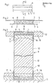
- FIGS. 1 to 3 An edge insulation strip 1 according to the invention can be seen from FIGS. 1 to 3, which consists of an arbitrarily long, approximately 0.06 m wide and 0.008 m thick sound-absorbing surface material made of large-pore foam.
- the two opposing supports / connecting surfaces 2, 3 are covered with easily bendable, thin-sighted cover strips 4, 5 made of a translucent non-woven fabric made of plastic fibers. These cover strips 4, 5 protrude beyond the longitudinal side edges 6, 7 of the edge insulation strip 1 by more than the thickness d of the edge insulation strip 1, the lateral projection of the upper cover strip 5 being more than twice as large as the lower cover strip 4.
- At least the cover strip 5 is provided on its outside with a self-adhesive layer 8, which should preferably not be wider than the edge insulation strip 1 and should have good self-adhesive properties on the wall to be connected; there are a number of self-adhesive layers known per se.
- FIG. 3 shows a non-load-bearing partition 9 made of gypsum planks known per se, which is erected between a floor 11 and a self-supporting ceiling 12.
- the edge insulation strip 1 shown in FIG. 2, with cover strips 4, 5 and self-adhesive layer 8, has first been glued to the connection walls (floor 12 and ceiling 10) in the region of all end connection surfaces of the intermediate wall 9.
- a mortar layer 13 was first applied to the cover strip 4 of the lower edge insulation strip 1 and the gypsum plank boards 10 known per se were erected thereon in a known manner.
- the cover strips 4, 5 of the edge insulation strip glued to the still unplastered ceiling 12 initially protrude horizontally.
- the space between the edge insulation strip and the upper edge of the intermediate wall 9 was then filled with a layer of mortar or plaster 14 in a manner known per se.
- the two cover strips 4, 5 are bent together or one after the other in the direction of the intermediate wall 9 and applied to the preferably not yet set mortar layer 13, 14.
- the ceiling plaster 15 or the screed 16 is applied with or without an insulating layer 17 in a manner known per se.
- the ceiling plaster or screed lies directly against the folded cover strip 5 without a non-positive connection to the material of the intermediate wall 9 being created.
- the intermediate wall is built in sufficiently firmly and ceiling or floor movements are absorbed by the edge insulation strip 1 without new sound bridges being created. Cover strips enter into a good adhesive bond with respect to the mortar or plaster adjoining them, and the longitudinal edge surfaces of the edge insulation strip 1 do not come into contact with plaster or mortar or the like.
- the surface material of the edge insulation strip 1 consists of foam, in particular a cross-linked polyolefin foam.
- Cross-linked polyethylene foam has proven particularly useful here. Such crosslinked polyolefin or polyethylene foams are known. You will e.g. B. radiation cross-linking.
- edge insulation strip 1 can additionally be covered by at least one further layer of open-cell soft foam and / or a soft-elastic nonwoven fabric.
- flexible polyurethane foam is also suitable as a closed-cell soft foam. This has the advantage that polyurethane foam can be glued directly to any carrier layers. It is essential that the airtight, closed-cell soft foam has a loss factor h> 0.01, the mean distance of the statistical spatial distribution of the heavy mass particles being small compared to the wavelength of the absorbing airborne sound and that the total weight of the mass particles being approximately the same as that of the soft foam. Edge insulation strips of this type are particularly effective.
- the size of the heavy mass particles is adapted to the respective use and depends on the surface material of the edge insulation strip.
- the mass particles stored therein should be as punctiform as possible with a statistical distribution. The average distance from each other should be small compared to the air wavelength. In the lower frequency range of effectiveness, and the total weight of the mass particles introduced per unit area should be approximately the same as that of the foam layer.
- the attachment of the mass particles is very easy in terms of manufacturing technology.
- the balls heated to a suitable temperature, can be sprinkled onto the foam sheet and pressed in with slight pressure, whereby they firmly adhere to the sheet by melting the foam.
- the surface material of the edge insulation strip with an additional layer of open-cell soft foam and / or a soft elastic nonwoven fabric.
- the cover strips on the longitudinal side edges of the edge insulation strip expediently consist of a material that can be easily glued to the construction material of the non-load-bearing partition. For this reason, nonwoven strips in particular have proven themselves, which have good adhesion e.g. go with plaster. As is well known, polyolefin foams cannot easily be glued to gypsum.
- the edge insulation strip also provides good sound insulation if the distance between the ceiling and the non-load-bearing wall changes over time, because the material of the edge insulation strip is flexible and there is no impairment of the sound insulation effect as part of the volume change caused by the "working" of the building.
Landscapes
- Engineering & Computer Science (AREA)
- Architecture (AREA)
- Physics & Mathematics (AREA)
- Electromagnetism (AREA)
- Civil Engineering (AREA)
- Structural Engineering (AREA)
- Building Environments (AREA)
Applications Claiming Priority (2)
| Application Number | Priority Date | Filing Date | Title |
|---|---|---|---|
| DE19848437422 DE8437422U1 (de) | 1984-12-21 | 1984-12-21 | Randdaemmstreifen |
| DE8437422U | 1984-12-21 |
Publications (2)
| Publication Number | Publication Date |
|---|---|
| EP0185172A2 true EP0185172A2 (fr) | 1986-06-25 |
| EP0185172A3 EP0185172A3 (fr) | 1987-05-06 |
Family
ID=6774008
Family Applications (1)
| Application Number | Title | Priority Date | Filing Date |
|---|---|---|---|
| EP85113593A Withdrawn EP0185172A3 (fr) | 1984-12-21 | 1985-10-25 | Bande isolante d'extrémité |
Country Status (3)
| Country | Link |
|---|---|
| EP (1) | EP0185172A3 (fr) |
| DE (1) | DE8437422U1 (fr) |
| ES (1) | ES291191Y (fr) |
Cited By (3)
| Publication number | Priority date | Publication date | Assignee | Title |
|---|---|---|---|---|
| GB2322883A (en) * | 1997-03-06 | 1998-09-09 | Ecomax Acoustics Ltd | Partitioning providing acoustic insulation |
| EP0863269A3 (fr) * | 1997-03-06 | 1999-02-03 | Ecomax Acoustics Limited | Système de support de cloisons et spécialement de plaques de cloisons devant assurer une isolation acoustique |
| WO2010144935A3 (fr) * | 2009-06-15 | 2012-02-02 | Url Guenter | Bande de raccordement pour disposition entre une construction à pose à sec |
Families Citing this family (3)
| Publication number | Priority date | Publication date | Assignee | Title |
|---|---|---|---|---|
| DE20115715U1 (de) | 2001-02-21 | 2002-01-17 | Deutsche Rockwool Mineralwoll GmbH & Co. oHG, 45966 Gladbeck | Selbstklebende Dämmstoffstreifen |
| DE10201156B4 (de) * | 2002-01-15 | 2004-09-09 | Paul Bauder Gmbh & Co. | Schalldämmung für eine Gebäudetrennwand |
| JP7757117B2 (ja) * | 2021-09-30 | 2025-10-21 | 大和ハウス工業株式会社 | 室内構造 |
Family Cites Families (3)
| Publication number | Priority date | Publication date | Assignee | Title |
|---|---|---|---|---|
| NL6407593A (fr) * | 1963-07-08 | 1965-01-11 | ||
| US3386527A (en) * | 1965-08-05 | 1968-06-04 | Daubert Chemical Co | Adhesive sound damping tape for application to vibrating panels |
| DE2147075A1 (de) * | 1971-09-21 | 1973-03-29 | Horst R Dipl Ing Gruen | Anschluss einer trennwand an eine decke oder an eine die trennwand durchbrechende rohrleitung |
-
1984
- 1984-12-21 DE DE19848437422 patent/DE8437422U1/de not_active Expired
-
1985
- 1985-10-25 EP EP85113593A patent/EP0185172A3/fr not_active Withdrawn
- 1985-12-20 ES ES1985291191U patent/ES291191Y/es not_active Expired
Cited By (3)
| Publication number | Priority date | Publication date | Assignee | Title |
|---|---|---|---|---|
| GB2322883A (en) * | 1997-03-06 | 1998-09-09 | Ecomax Acoustics Ltd | Partitioning providing acoustic insulation |
| EP0863269A3 (fr) * | 1997-03-06 | 1999-02-03 | Ecomax Acoustics Limited | Système de support de cloisons et spécialement de plaques de cloisons devant assurer une isolation acoustique |
| WO2010144935A3 (fr) * | 2009-06-15 | 2012-02-02 | Url Guenter | Bande de raccordement pour disposition entre une construction à pose à sec |
Also Published As
| Publication number | Publication date |
|---|---|
| ES291191U (es) | 1986-12-16 |
| ES291191Y (es) | 1987-08-01 |
| EP0185172A3 (fr) | 1987-05-06 |
| DE8437422U1 (de) | 1985-04-25 |
Similar Documents
| Publication | Publication Date | Title |
|---|---|---|
| DE69834368T2 (de) | Unterteilte eingekapselte isolationseinheit | |
| DE3643481A1 (de) | Schallschluckbeschichtung einer akustikwand oder akustikdecke | |
| EP3256666A1 (fr) | Bande d'étanchéité de jointure universelle pour différentes dimensions de profilé et dispositif d'étanchéité pourvu d'une telle bande d'étanchéité de jointure | |
| EP3256663A1 (fr) | Bande d'étanchéité de jointure à géométrie prédéterminée et dispositif d'étanchéité comprenant une bande d'étanchéité de jointure de ce type | |
| DE1559569A1 (de) | Monolithisches Bauelement | |
| DE19643618C5 (de) | Wärmedämmverbundsystem | |
| EP0185172A2 (fr) | Bande isolante d'extrémité | |
| EP1525358B1 (fr) | Couche isolante en fibres minerales et paroi de batiment | |
| DE3136935C1 (de) | Bahn oder Platte aus Mineralwolle, insbesondere Steinwolle | |
| DE3409592A1 (de) | Waermedaemmsystem | |
| EP2006462B1 (fr) | Plaque multicouche acoustique | |
| DE202012100418U1 (de) | Gebäudefassade mit Riegelelement und Riegelelement | |
| EP2960392A1 (fr) | Élément de coffrage de bordure | |
| EP0982444B1 (fr) | Dispositif pour éviter l' extension du feu aux bâtiments | |
| DE10227736B4 (de) | Wärmedämmverbundsystem und Mineralfaserlamelle | |
| EP0664365B1 (fr) | Panneau pour plafond | |
| EP1295998B1 (fr) | Isolation acoustique et thermique; Elément d'isolation et lamelle de fibres minérales | |
| DE3021537A1 (de) | Isolierung fuer den hoch- und tiefbau | |
| EP1527237B1 (fr) | Element isolant et mur de construction | |
| DE19636983A1 (de) | Ständerelement für die Erstellung von Leichtbau-Tennwänden | |
| DE8500260U1 (de) | Dachelement mit hoher luftschalldaemmung | |
| AT406697B (de) | Mehrschicht-leichtbauplatte | |
| AT211523B (de) | Feuchtigkeits- und dampfsperrender, gegebenenfalls auch schall- und wärmeisolierender Bauteil | |
| AT4079U1 (de) | Bauvorsatzschale mit feuerschutz-schallschutz-eigenschaften | |
| DE1901727A1 (de) | Zweischalige leichte Trennwand |
Legal Events
| Date | Code | Title | Description |
|---|---|---|---|
| PUAI | Public reference made under article 153(3) epc to a published international application that has entered the european phase |
Free format text: ORIGINAL CODE: 0009012 |
|
| AK | Designated contracting states |
Kind code of ref document: A2 Designated state(s): AT BE CH DE FR GB IT LI NL |
|
| PUAL | Search report despatched |
Free format text: ORIGINAL CODE: 0009013 |
|
| AK | Designated contracting states |
Kind code of ref document: A3 Designated state(s): AT BE CH DE FR GB IT LI NL |
|
| 17P | Request for examination filed |
Effective date: 19870327 |
|
| STAA | Information on the status of an ep patent application or granted ep patent |
Free format text: STATUS: THE APPLICATION HAS BEEN WITHDRAWN |
|
| 18W | Application withdrawn |
Withdrawal date: 19880317 |
|
| RIN1 | Information on inventor provided before grant (corrected) |
Inventor name: QUITTMANN, JUERGEN Inventor name: GERRIETS, GERRIT D.A. |