EP0185615A2 - Verfahren zur Herstellung eines optischen Faserkabels, das nach diesem Verfahren hergestellte Kabel und Vorrichtung zum Durchführen des Verfahrens - Google Patents
Verfahren zur Herstellung eines optischen Faserkabels, das nach diesem Verfahren hergestellte Kabel und Vorrichtung zum Durchführen des Verfahrens Download PDFInfo
- Publication number
- EP0185615A2 EP0185615A2 EP85810574A EP85810574A EP0185615A2 EP 0185615 A2 EP0185615 A2 EP 0185615A2 EP 85810574 A EP85810574 A EP 85810574A EP 85810574 A EP85810574 A EP 85810574A EP 0185615 A2 EP0185615 A2 EP 0185615A2
- Authority
- EP
- European Patent Office
- Prior art keywords
- envelope
- temperature
- wiring element
- cooling
- guide member
- Prior art date
- Legal status (The legal status is an assumption and is not a legal conclusion. Google has not performed a legal analysis and makes no representation as to the accuracy of the status listed.)
- Granted
Links
Images
Classifications
-
- G—PHYSICS
- G02—OPTICS
- G02B—OPTICAL ELEMENTS, SYSTEMS OR APPARATUS
- G02B6/00—Light guides; Structural details of arrangements comprising light guides and other optical elements, e.g. couplings
- G02B6/44—Mechanical structures for providing tensile strength and external protection for fibres, e.g. optical transmission cables
- G02B6/4479—Manufacturing methods of optical cables
- G02B6/4484—Manufacturing methods of optical cables with desired surplus length between fibres and protection features
-
- B—PERFORMING OPERATIONS; TRANSPORTING
- B29—WORKING OF PLASTICS; WORKING OF SUBSTANCES IN A PLASTIC STATE IN GENERAL
- B29C—SHAPING OR JOINING OF PLASTICS; SHAPING OF MATERIAL IN A PLASTIC STATE, NOT OTHERWISE PROVIDED FOR; AFTER-TREATMENT OF THE SHAPED PRODUCTS, e.g. REPAIRING
- B29C48/00—Extrusion moulding, i.e. expressing the moulding material through a die or nozzle which imparts the desired form; Apparatus therefor
- B29C48/03—Extrusion moulding, i.e. expressing the moulding material through a die or nozzle which imparts the desired form; Apparatus therefor characterised by the shape of the extruded material at extrusion
- B29C48/05—Filamentary, e.g. strands
-
- G—PHYSICS
- G02—OPTICS
- G02B—OPTICAL ELEMENTS, SYSTEMS OR APPARATUS
- G02B6/00—Light guides; Structural details of arrangements comprising light guides and other optical elements, e.g. couplings
- G02B6/44—Mechanical structures for providing tensile strength and external protection for fibres, e.g. optical transmission cables
- G02B6/4479—Manufacturing methods of optical cables
-
- B—PERFORMING OPERATIONS; TRANSPORTING
- B29—WORKING OF PLASTICS; WORKING OF SUBSTANCES IN A PLASTIC STATE IN GENERAL
- B29C—SHAPING OR JOINING OF PLASTICS; SHAPING OF MATERIAL IN A PLASTIC STATE, NOT OTHERWISE PROVIDED FOR; AFTER-TREATMENT OF THE SHAPED PRODUCTS, e.g. REPAIRING
- B29C48/00—Extrusion moulding, i.e. expressing the moulding material through a die or nozzle which imparts the desired form; Apparatus therefor
Definitions
- the object of the present invention is to carry out a simple method making it possible to give the light wave guide members the necessary extra length inside the envelope (s).
- a first object of the invention is a method of manufacturing a fiber optic cabling element comprising the passage of a light wave guiding member in an extrusion head, the formation in this head.
- a protective envelope around the guide member and then the cooling of the envelope characterized in that the cooling is carried out in two successive stages, the guide member and the envelope are subjected to tensile forces predetermined during the first cooling step while during the second step, the guide member is free and the casing is subjected to a tensile force as low as possible and in that the cooling temperature obtained during of the second stage is less than that obtained during the first stage.
- the invention also relates to a wiring element obtained by this method.
- the cooling device comprises a first tank adjusted to cool the wiring element to a first temperature T 1 , a main withdrawer pulling the wiring element through the extrusion head and the first tank, a second tank adjusted to cool the envelope to a second temperature T, lower than the temperature T 1 and a withdrawer auxiliary capable of pulling the wiring element through the second bin with as low a pulling force as possible and in that the receiving device is capable of receiving and driving reels rec to store the wiring element at the output of the auxiliary withdrawer.
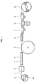
- a member for guiding the light waves which will be called hereinafter "fiber-optics", designated by 1, is carried on a supply coil 2 and delivered under a voltage Ff maintained at a value guaranteeing that the fiber remains taut until to the main withdrawer 5.
- This tension Ff is maintained by means of a magnetic brake 2a, acting on the supply coil 2.
- the value of this tension can vary between 20 and 100 gr.
- the optical fiber 1 enters the extrusion head 3 which is fed by a conventional extruder, so that a plastic envelope forms around the fiber 1, this envelope being designated by 11 Leaving the head 3, the fiber 1 is therefore coated with the envelope 11, this operation being carried out so that the fiber 1 remains free inside the envelope 11.
- the latter then enters a first container cooling 4, for example supplied with water and adjusted so that the coated fiber is maintained at a predetermined temperature T 1 .
- the length of this tank is calculated as a function of the speed of passage of the envelope 11 so as to stabilize the temperature of the envelope 11, even for the maximum speed that the line can deliver.
- the envelope 11 therefore has a temperature equal to T 1 . It passes over the main withdrawer 5, constituted for example by a large diameter pulley on which the casing 11 makes several turns.
- the main withdrawer is rotated at a constant speed so as to ensure the passage of the fiber 1 through the extrusion head 3.
- the withdrawer 5 is maintained at the temperature T 1 .
- it can be housed inside the container 4 .
- the envelope 11 enters a second cooling tank 6 designed so as to bring the envelope 11 to a temperature T, lower than the temperature T 1 .
- This temperature T will even be lower than the ambient temperature, at which the wiring elements completed and received on the receiving coils 10 will be stored.
- an auxiliary withdrawer 8 is provided, capable of storing a certain length of wiring element and two jacks 7 and 9, arranged, run between the tank 6 and the withdrawer auxiliary 8, and the other between the latter and the winder 10 carrying the take-up reel.
- These jacks 7 and 9 are designed so as to ensure the displacement of the wiring element under a voltage Ft as low as possible.
- the temperature T corresponds to a partial cooling of the casing 11 and of the guide element 1.
- the value of this temperature will be determined according to the dimensions and the materials used. It will preferably be higher than room temperature.
- the determining effect for obtaining the desired result is the fact that after the contraction undergone by the casing 11 during the second cooling step, under as low a tension as possible, the length of the casing 11 is fixed on the auxiliary withdrawer and on the take-up reel, so that the extra length of the light wave guide element (s) is preserved. This extra length is therefore determined by the difference in cooling temperatures (T 2 - T 1 ).
- the cooling of the wiring element is carried out in two stages, that is to say a first stage of cooling carried out under a predetermined voltage, ensuring the drawing of the optical fiber through the extrusion head then a second stage carried out by ensuring a state of zero tension on the wiring element so that the envelope can contract freely This free contraction gives the optical fiber a slight excess length in its envelope which makes it possible to then handle the wiring element without risking the deterioration of the fiber.
Landscapes
- Physics & Mathematics (AREA)
- Engineering & Computer Science (AREA)
- Manufacturing & Machinery (AREA)
- General Physics & Mathematics (AREA)
- Optics & Photonics (AREA)
- Mechanical Engineering (AREA)
- Extrusion Moulding Of Plastics Or The Like (AREA)
- Surface Treatment Of Glass Fibres Or Filaments (AREA)
- Manufacturing Of Electric Cables (AREA)
- Golf Clubs (AREA)
- Ultra Sonic Daignosis Equipment (AREA)
- Investigating Or Analysing Biological Materials (AREA)
- Light Guides In General And Applications Therefor (AREA)
Priority Applications (1)
| Application Number | Priority Date | Filing Date | Title |
|---|---|---|---|
| AT85810574T ATE68166T1 (de) | 1984-12-14 | 1985-12-04 | Verfahren zur herstellung eines optischen faserkabels, das nach diesem verfahren hergestellte kabel und vorrichtung zum durchfuehren des verfahrens. |
Applications Claiming Priority (2)
| Application Number | Priority Date | Filing Date | Title |
|---|---|---|---|
| CH5966/84 | 1984-12-14 | ||
| CH5966/84A CH660801A5 (fr) | 1984-12-14 | 1984-12-14 | Procede de fabrication d'un element de cablage a fibre optique, installation pour la mise en oeuvre du procede et element de cablage obtenu par ce procede. |
Publications (3)
| Publication Number | Publication Date |
|---|---|
| EP0185615A2 true EP0185615A2 (de) | 1986-06-25 |
| EP0185615A3 EP0185615A3 (en) | 1987-09-09 |
| EP0185615B1 EP0185615B1 (de) | 1991-10-09 |
Family
ID=4302245
Family Applications (1)
| Application Number | Title | Priority Date | Filing Date |
|---|---|---|---|
| EP85810574A Expired - Lifetime EP0185615B1 (de) | 1984-12-14 | 1985-12-04 | Verfahren zur Herstellung eines optischen Faserkabels, das nach diesem Verfahren hergestellte Kabel und Vorrichtung zum Durchführen des Verfahrens |
Country Status (7)
| Country | Link |
|---|---|
| US (2) | US4772435A (de) |
| EP (1) | EP0185615B1 (de) |
| JP (1) | JPS61141412A (de) |
| AT (1) | ATE68166T1 (de) |
| CH (1) | CH660801A5 (de) |
| DE (1) | DE3584360D1 (de) |
| FI (1) | FI854907A7 (de) |
Cited By (3)
| Publication number | Priority date | Publication date | Assignee | Title |
|---|---|---|---|---|
| FR2704070A1 (fr) * | 1993-04-14 | 1994-10-21 | Kertscher Sa E | Installation et procédé de fabrication d'un câble à fibre optique. |
| EP0785451A1 (de) * | 1996-01-19 | 1997-07-23 | Alcatel | Optisches Kabel mit peripheren extrudierten Verstärkungselementen |
| US6003340A (en) * | 1994-03-15 | 1999-12-21 | Telefonaktiebolaget Lm Ericsson | Method of putting a bend into a fiber to make a strain sensor |
Families Citing this family (18)
| Publication number | Priority date | Publication date | Assignee | Title |
|---|---|---|---|---|
| EP0275994B1 (de) * | 1987-01-23 | 1993-04-07 | Siemens Aktiengesellschaft | Verfahren und Vorrichtung zur Herstellung von definierten Lichtwellenleiterlängen in Lichtleitadern |
| FI83914C (fi) * | 1989-10-20 | 1991-09-10 | Maillefer Nokia Holding | Foerfarande och utrustning foer tillverkning av ett flerfibrigt optiskt ledarelement. |
| US5080838A (en) * | 1990-08-10 | 1992-01-14 | U.S. Philips Corp. | Method of producing an optical cable |
| US5372757A (en) * | 1993-09-03 | 1994-12-13 | Tensor Machinery Ltd. | Apparatus and method for sheathing optical fibers |
| FI105599B (fi) * | 1995-07-06 | 2000-09-15 | Nokia Kaapeli Oy | Menetelmä ja sovitelma monielementtisen optisen kaapelin perusosan valmistamiseksi |
| JP3070560B2 (ja) * | 1997-01-30 | 2000-07-31 | 住友電気工業株式会社 | 自己支持型光ケーブルの製造方法 |
| FI104589B (fi) | 1997-11-10 | 2000-02-29 | Nextrom Holding Sa | Menetelmä ja sovitelma toisiopäällystyslinjan yhteydessä |
| US6066275A (en) * | 1998-07-07 | 2000-05-23 | Alcatel | Method and apparatus for determining and controlling excess length of a communications element in a conduit |
| US6827884B2 (en) * | 1998-12-29 | 2004-12-07 | Pirelli Cavi E Sistemi S.P.A. | Method and apparatus for manufacturing an optical fibre cable and cable so manufactured |
| US7373055B1 (en) | 2007-01-09 | 2008-05-13 | Draka Comteq B.V. | System and method for providing a buffer tube including a jet |
| US7970247B2 (en) * | 2008-09-12 | 2011-06-28 | Draka Comteq B.V. | Buffer tubes for mid-span storage |
| US8489219B1 (en) | 2009-01-30 | 2013-07-16 | Draka Comteq B.V. | Process for making loose buffer tubes having controlled excess fiber length and reduced post-extrusion shrinkage |
| US8625944B1 (en) | 2009-05-13 | 2014-01-07 | Draka Comteq, B.V. | Low-shrink reduced-diameter buffer tubes |
| US8625945B1 (en) | 2009-05-13 | 2014-01-07 | Draka Comteq, B.V. | Low-shrink reduced-diameter dry buffer tubes |
| EP3314322B1 (de) * | 2015-06-26 | 2020-08-05 | Prysmian S.p.A. | Verfahren zur herstellung eines optischen mikromodul-luftkabels |
| CN105150497A (zh) * | 2015-09-11 | 2015-12-16 | 长飞光纤光缆股份有限公司 | 一种冷却长度机动可调的多路径高效塑料管冷却装置及方法 |
| FR3093039B1 (fr) * | 2019-02-22 | 2021-10-01 | Sealynx Int | Elément fonctionnel lumineux pour véhicule automobile |
| CA3231872A1 (en) | 2021-09-14 | 2023-03-23 | Technical Development Corporation | Quad wheel buffering tube clencher capstan |
Family Cites Families (27)
| Publication number | Priority date | Publication date | Assignee | Title |
|---|---|---|---|---|
| US3055778A (en) * | 1960-03-23 | 1962-09-25 | Swift & Co | Method for applying a mixture of a vinyl halide polymer and an epoxidized triglyceride on a wire and the resulting article |
| US3604392A (en) * | 1968-01-09 | 1971-09-14 | Sumitomo Electric Industries | Apparatus for manufacturing a plastic insulated wire |
| US3544665A (en) * | 1969-01-24 | 1970-12-01 | Schlumberger Technology Corp | Method and apparatus for manufacturing electrical conductors |
| DE1942784B1 (de) * | 1969-08-22 | 1971-02-04 | Ibm Deutschland | Verfahren zum Ummanteln von Bandkabeln |
| US3729539A (en) * | 1970-06-30 | 1973-04-24 | Gen Engineering Co | Cooling of plastic extrusions of small cross-sectional area |
| US3849192A (en) * | 1972-05-12 | 1974-11-19 | Gen Cable Corp Inc | Method of applying and cooling low density polyethylene cable insulation |
| CH585458A5 (de) * | 1975-01-28 | 1977-02-28 | Daetwyler Ag | |
| US4154783A (en) * | 1975-05-14 | 1979-05-15 | The Post Office | Process for producing dielectric optical waveguides |
| JPS5284482A (en) * | 1976-01-06 | 1977-07-14 | Ube Industries | Method of covering insulator for core used for marine coaxial cable |
| CA1075331A (en) * | 1976-02-05 | 1980-04-08 | Western Electric Company, Incorporated | Dual jacketed cable and methods of making |
| JPS6055802B2 (ja) * | 1976-02-16 | 1985-12-06 | 古河電気工業株式会社 | 光通信ケ−ブルの製造方法 |
| US4089923A (en) * | 1977-02-17 | 1978-05-16 | International Telephone & Telegraph Corporation | Manufacture of submarine cable |
| FR2388930A1 (fr) * | 1977-04-27 | 1978-11-24 | Lignes Telegraph Telephon | Procede de fabrication en ligne d'elements de cablage a fibres optiques |
| JPS5928009B2 (ja) * | 1977-05-23 | 1984-07-10 | 古河電気工業株式会社 | 通信用絶縁被覆線の製造方法 |
| US4369688A (en) * | 1977-10-17 | 1983-01-25 | E. I. Du Pont De Nemours And Company | Method and apparatus for producing a detonating cord |
| GB2013927A (en) * | 1978-01-30 | 1979-08-15 | Telephone Cables Ltd | Manufacture of elongate optical fibre waveguide structures |
| GB2017335B (en) * | 1978-03-15 | 1982-06-23 | Bicc Ltd | Manufacture of optical fibre cable |
| DE2845887A1 (de) * | 1978-10-21 | 1980-04-30 | Aeg Telefunken Kabelwerke | Verfahren zur herstellung einer lichtleiteranordnung |
| DE2907704B2 (de) * | 1979-02-28 | 1981-03-12 | Siemens AG, 1000 Berlin und 8000 München | Verseilelement für optische Kabel |
| GB2079970B (en) * | 1980-07-09 | 1984-04-18 | Bicc Ltd | Improvements in or relating to optical cable elements |
| DE3111963C2 (de) * | 1981-03-26 | 1986-07-17 | Siemens AG, 1000 Berlin und 8000 München | Verfahren und Einrichtung zur Herstellung einer Lichtwellenleiter-Ader |
| DE3121222A1 (de) * | 1981-05-27 | 1982-12-23 | Siemens AG, 1000 Berlin und 8000 München | Verfahren und einrichtung zur herstellung eines optischen uebertragungselementes. |
| JPS5823004A (ja) * | 1981-08-03 | 1983-02-10 | Sumitomo Electric Ind Ltd | 光フアイバ心線のたるみ付け撚合せ装置 |
| CA1200062A (en) * | 1981-12-22 | 1986-02-04 | Bicc Public Limited Company | Optical cable elements |
| DE3239024A1 (de) * | 1982-10-21 | 1984-04-26 | Siemens AG, 1000 Berlin und 8000 München | Einrichtung zur umhuellung einer aus lichtwellenleitern aufgebauten strangfoermigen einheit |
| US4583929A (en) * | 1983-02-25 | 1986-04-22 | U.S. Philips Corporation | Apparatus for manufacturing an optical cable element |
| FI75939C (fi) * | 1983-05-30 | 1988-08-08 | Nokia Oy Ab | Foerfarande och anordning foer att aostadkomma en oeverlopps fiberlaengd vid sekundaermantling av en optisk fiber. |
-
1984
- 1984-12-14 CH CH5966/84A patent/CH660801A5/fr not_active IP Right Cessation
-
1985
- 1985-12-03 US US06/804,119 patent/US4772435A/en not_active Expired - Lifetime
- 1985-12-04 AT AT85810574T patent/ATE68166T1/de not_active IP Right Cessation
- 1985-12-04 DE DE8585810574T patent/DE3584360D1/de not_active Expired - Lifetime
- 1985-12-04 EP EP85810574A patent/EP0185615B1/de not_active Expired - Lifetime
- 1985-12-11 FI FI854907A patent/FI854907A7/fi not_active IP Right Cessation
- 1985-12-13 JP JP60280863A patent/JPS61141412A/ja active Granted
-
1988
- 1988-05-23 US US07/197,314 patent/US4893998A/en not_active Expired - Fee Related
Cited By (5)
| Publication number | Priority date | Publication date | Assignee | Title |
|---|---|---|---|---|
| FR2704070A1 (fr) * | 1993-04-14 | 1994-10-21 | Kertscher Sa E | Installation et procédé de fabrication d'un câble à fibre optique. |
| WO1994024595A1 (fr) * | 1993-04-14 | 1994-10-27 | E. Kertscher S.A. | Installation et procede de fabrication d'un cable a fibre optique |
| US5676892A (en) * | 1993-04-14 | 1997-10-14 | E. Kertscher S.A. | Installation and method for manufacture of an optical fiber cable |
| US6003340A (en) * | 1994-03-15 | 1999-12-21 | Telefonaktiebolaget Lm Ericsson | Method of putting a bend into a fiber to make a strain sensor |
| EP0785451A1 (de) * | 1996-01-19 | 1997-07-23 | Alcatel | Optisches Kabel mit peripheren extrudierten Verstärkungselementen |
Also Published As
| Publication number | Publication date |
|---|---|
| FI854907L (fi) | 1986-06-15 |
| FI854907A0 (fi) | 1985-12-11 |
| EP0185615B1 (de) | 1991-10-09 |
| DE3584360D1 (de) | 1991-11-14 |
| ATE68166T1 (de) | 1991-10-15 |
| FI854907A7 (fi) | 1986-06-15 |
| US4893998A (en) | 1990-01-16 |
| US4772435A (en) | 1988-09-20 |
| CH660801A5 (fr) | 1987-06-15 |
| EP0185615A3 (en) | 1987-09-09 |
| JPS61141412A (ja) | 1986-06-28 |
| JPH055325B2 (de) | 1993-01-22 |
Similar Documents
| Publication | Publication Date | Title |
|---|---|---|
| EP0185615A2 (de) | Verfahren zur Herstellung eines optischen Faserkabels, das nach diesem Verfahren hergestellte Kabel und Vorrichtung zum Durchführen des Verfahrens | |
| FR2655765A1 (fr) | Cable pour ligne electrique aerienne de transport d'energie, et procedes et dispositifs de fabrication d'un tel cable. | |
| EP0696750B1 (de) | Herstellungsverfahren für ein verstärktes faseroptisches Kabel, zugehörige Vorrichtung und Kabel mittels diesem Verfahren gefertigt | |
| FI115003B (fi) | Menetelmä valokaapelin valmistamiseksi metalliputkesta | |
| EP0420721B1 (de) | Verfahren zur Doppelaufwicklung eines Kabels oder dergleichen auf der Aussenfläche einer Trommel | |
| CA1189584A (fr) | Cable de telecommande a element central textile positionne | |
| EP0235753B1 (de) | Herstellungsvorrichtung und Verfahren für die Erzeugung einer extrudierten Hülse versehen mit mindestens einer optischen Faser | |
| FR2677919A1 (fr) | Procede de fabrication d'un ruban de polytetrafluoroethylene de grande porosite, ruban poreux obtenu et utilisation dudit ruban. | |
| EP0364317A1 (de) | Optisches Kabel | |
| EP0518738B1 (de) | Herstellungsverfahren für ein optisches Kabel aus Hohladern und daraus resultierendes Kabel | |
| US6327767B1 (en) | Method and apparatus for the continuous manufacture of fiber-optic cable | |
| EP0311941B1 (de) | Fabrikationsverfahren für ein optisches Kabel und danach hergestelltes Kabel | |
| EP0171299B1 (de) | Zugrad für die Herstellung von optischen Kabeln | |
| EP1514147B1 (de) | Verfahren zur herstellung eines optischen kabels und diesbezügliche maschine | |
| EP0728117B1 (de) | Verfahren zur versetzten anordnung der lagen einer wicklung | |
| EP0252012B1 (de) | Einrichtung für die Einführung einer Vielzahl optischer Fasern in die Nuten eines Profilkörpers und die Einstellmethode ihrer Überlängen in den Nuten | |
| EP0886902A1 (de) | Geschütztes wellrohrmit schallisolierung | |
| FR2616530A1 (fr) | Bobine de fil de guidage pour missiles | |
| EP0208587A1 (de) | Verfahren zum Einbringen optischer Fasern in röhrenförmige Hüllen und Vorrichtung hierfür | |
| FR2653946A1 (fr) | Procede de deroulage et de mise en place d'un cable a fibres optiques et installation pour la mise en óoeuvre de ce procede. | |
| JPH09197209A (ja) | 光ファイバテープ心線 | |
| JP3502240B2 (ja) | 光ファイバケーブル用合成樹脂ユニットの製造方法および光ファイバケーブルの製造方法 | |
| EP2548710B1 (de) | Herstellungsverfahren eines mikrorohrs | |
| FR2532440A1 (fr) | Cable optique a caracteristiques mecaniques ameliorees | |
| FR2553902A1 (fr) | Procede de fabrication d'un cable a fibres optiques ne comportant aucun materiau conducteur de l'electricite |
Legal Events
| Date | Code | Title | Description |
|---|---|---|---|
| PUAI | Public reference made under article 153(3) epc to a published international application that has entered the european phase |
Free format text: ORIGINAL CODE: 0009012 |
|
| AK | Designated contracting states |
Kind code of ref document: A2 Designated state(s): AT BE CH DE FR GB IT LI NL SE |
|
| PUAL | Search report despatched |
Free format text: ORIGINAL CODE: 0009013 |
|
| AK | Designated contracting states |
Kind code of ref document: A3 Designated state(s): AT BE CH DE FR GB IT LI NL SE |
|
| 17P | Request for examination filed |
Effective date: 19871121 |
|
| 17Q | First examination report despatched |
Effective date: 19880916 |
|
| RAP1 | Party data changed (applicant data changed or rights of an application transferred) |
Owner name: NOKIA-MAILLEFER S.A. |
|
| GRAA | (expected) grant |
Free format text: ORIGINAL CODE: 0009210 |
|
| AK | Designated contracting states |
Kind code of ref document: B1 Designated state(s): AT BE CH DE FR GB IT LI NL SE |
|
| REF | Corresponds to: |
Ref document number: 68166 Country of ref document: AT Date of ref document: 19911015 Kind code of ref document: T |
|
| REF | Corresponds to: |
Ref document number: 3584360 Country of ref document: DE Date of ref document: 19911114 |
|
| ITF | It: translation for a ep patent filed | ||
| GBT | Gb: translation of ep patent filed (gb section 77(6)(a)/1977) | ||
| PLBI | Opposition filed |
Free format text: ORIGINAL CODE: 0009260 |
|
| 26 | Opposition filed |
Opponent name: SIEMENS AG GR PA 7 Effective date: 19920612 |
|
| NLR1 | Nl: opposition has been filed with the epo |
Opponent name: SIEMENS AG |
|
| PGFP | Annual fee paid to national office [announced via postgrant information from national office to epo] |
Ref country code: CH Payment date: 19931207 Year of fee payment: 9 |
|
| PGFP | Annual fee paid to national office [announced via postgrant information from national office to epo] |
Ref country code: FR Payment date: 19941108 Year of fee payment: 10 |
|
| PGFP | Annual fee paid to national office [announced via postgrant information from national office to epo] |
Ref country code: GB Payment date: 19941116 Year of fee payment: 10 |
|
| PGFP | Annual fee paid to national office [announced via postgrant information from national office to epo] |
Ref country code: DE Payment date: 19941122 Year of fee payment: 10 |
|
| PGFP | Annual fee paid to national office [announced via postgrant information from national office to epo] |
Ref country code: BE Payment date: 19941125 Year of fee payment: 10 |
|
| PGFP | Annual fee paid to national office [announced via postgrant information from national office to epo] |
Ref country code: SE Payment date: 19941128 Year of fee payment: 10 |
|
| RDAG | Patent revoked |
Free format text: ORIGINAL CODE: 0009271 |
|
| STAA | Information on the status of an ep patent application or granted ep patent |
Free format text: STATUS: PATENT REVOKED |
|
| PGFP | Annual fee paid to national office [announced via postgrant information from national office to epo] |
Ref country code: AT Payment date: 19941230 Year of fee payment: 10 |
|
| PGFP | Annual fee paid to national office [announced via postgrant information from national office to epo] |
Ref country code: NL Payment date: 19941231 Year of fee payment: 10 |
|
| EUG | Se: european patent has lapsed |
Ref document number: 85810574.5 Effective date: 19950215 |
|
| 27W | Patent revoked |
Effective date: 19941129 |
|
| GBPR | Gb: patent revoked under art. 102 of the ep convention designating the uk as contracting state |
Free format text: 941129 |
|
| REG | Reference to a national code |
Ref country code: CH Ref legal event code: PL |
|
| NLR2 | Nl: decision of opposition | ||
| APAH | Appeal reference modified |
Free format text: ORIGINAL CODE: EPIDOSCREFNO |