EP0185840A2 - Steckbare Kontaktanordnung - Google Patents
Steckbare Kontaktanordnung Download PDFInfo
- Publication number
- EP0185840A2 EP0185840A2 EP85109339A EP85109339A EP0185840A2 EP 0185840 A2 EP0185840 A2 EP 0185840A2 EP 85109339 A EP85109339 A EP 85109339A EP 85109339 A EP85109339 A EP 85109339A EP 0185840 A2 EP0185840 A2 EP 0185840A2
- Authority
- EP
- European Patent Office
- Prior art keywords
- contact
- contact piece
- fingers
- piece
- section
- Prior art date
- Legal status (The legal status is an assumption and is not a legal conclusion. Google has not performed a legal analysis and makes no representation as to the accuracy of the status listed.)
- Withdrawn
Links
- 239000004020 conductor Substances 0.000 abstract description 5
- 238000006073 displacement reaction Methods 0.000 abstract description 3
- 238000004519 manufacturing process Methods 0.000 abstract description 3
- 238000005516 engineering process Methods 0.000 abstract description 2
- 238000005452 bending Methods 0.000 description 3
- 229910000881 Cu alloy Inorganic materials 0.000 description 1
- 229910000831 Steel Inorganic materials 0.000 description 1
- 230000002411 adverse Effects 0.000 description 1
- 230000005540 biological transmission Effects 0.000 description 1
- 238000005352 clarification Methods 0.000 description 1
- 230000001419 dependent effect Effects 0.000 description 1
- 230000002349 favourable effect Effects 0.000 description 1
- 238000009434 installation Methods 0.000 description 1
- 238000000926 separation method Methods 0.000 description 1
- 239000010959 steel Substances 0.000 description 1
Images

Classifications
-
- H—ELECTRICITY
- H01—ELECTRIC ELEMENTS
- H01R—ELECTRICALLY-CONDUCTIVE CONNECTIONS; STRUCTURAL ASSOCIATIONS OF A PLURALITY OF MUTUALLY-INSULATED ELECTRICAL CONNECTING ELEMENTS; COUPLING DEVICES; CURRENT COLLECTORS
- H01R13/00—Details of coupling devices of the kinds covered by groups H01R12/70 or H01R24/00 - H01R33/00
- H01R13/02—Contact members
- H01R13/10—Sockets for co-operation with pins or blades
- H01R13/11—Resilient sockets
- H01R13/111—Resilient sockets co-operating with pins having a circular transverse section
-
- H—ELECTRICITY
- H01—ELECTRIC ELEMENTS
- H01H—ELECTRIC SWITCHES; RELAYS; SELECTORS; EMERGENCY PROTECTIVE DEVICES
- H01H1/00—Contacts
- H01H1/12—Contacts characterised by the manner in which co-operating contacts engage
- H01H1/36—Contacts characterised by the manner in which co-operating contacts engage by sliding
- H01H1/38—Plug-and-socket contacts
-
- H—ELECTRICITY
- H01—ELECTRIC ELEMENTS
- H01R—ELECTRICALLY-CONDUCTIVE CONNECTIONS; STRUCTURAL ASSOCIATIONS OF A PLURALITY OF MUTUALLY-INSULATED ELECTRICAL CONNECTING ELEMENTS; COUPLING DEVICES; CURRENT COLLECTORS
- H01R13/00—Details of coupling devices of the kinds covered by groups H01R12/70 or H01R24/00 - H01R33/00
- H01R13/02—Contact members
- H01R13/33—Contact members made of resilient wire
-
- H—ELECTRICITY
- H01—ELECTRIC ELEMENTS
- H01R—ELECTRICALLY-CONDUCTIVE CONNECTIONS; STRUCTURAL ASSOCIATIONS OF A PLURALITY OF MUTUALLY-INSULATED ELECTRICAL CONNECTING ELEMENTS; COUPLING DEVICES; CURRENT COLLECTORS
- H01R13/00—Details of coupling devices of the kinds covered by groups H01R12/70 or H01R24/00 - H01R33/00
- H01R13/46—Bases; Cases
- H01R13/53—Bases or cases for heavy duty; Bases or cases for high voltage with means for preventing corona or arcing
Definitions
- the invention relates to a plug-in contact arrangement for connecting devices to one another or devices and switchgear parts for high-voltage technology according to the preamble of claim 1.
- Roller contacts have the advantage over sliding contacts that they reduce the forces required for the relative movement of the contact pieces.
- Roller contacts are rotationally symmetrical and rotatably mounted conductive bodies; they are known in various geometric shapes, e.g. as a truncated cone (DE-B 21 167 940), as a ball (DE-B 21 205 172), as a spherical cap (DE-C 31 003 323), as disks arranged in pairs on an axis
- the contact force with which one contact piece presses on the other is usually generated by means of steel springs which are designed as coil springs or leaf springs (DE-B 21 167 946; DE-C 31 142 940). If considerable contact forces are to be transmitted and a larger number of roller contacts are required, these arrangements usually have unfavorable radial dimensions which adversely affect the conductor spacing and thus the size of the devices and switchgear.
- plug connections have also become known in which the parts carrying the electrical current are also used to generate the contact force (DE-B 21 145 254).
- These parts are designed finger-like and as contact springs made of electrically good conductive material, e.g. Copper alloys. At their end they carry rollers provided in grooves which engage in corresponding grooves in the movable contact piece
- the contact springs that are subjected to bending can only exert an undefined contact force because this depends to a large extent on the length of the bending beam. Also occurs due to manufacturing and / or assembly tolerances due to an offset of the axes of the movable contact piece and the fixed contact piece, this means that not all contact fingers are involved in making contact. This arrangement is also unsuitable for the above-mentioned purposes as a plug-in connection because it only leads to reliable contacting at a defined distance between the movable and the fixed contact piece.
- the invention is therefore based on the object to provide a connector according to the preamble of claim 1, which is suitable for the transmission of large currents, which generates large and evenly distributed contact forces, regardless of whether there is a radial offset of the contact pieces to be connected .
- the plug connection should also be able to compensate for tolerances in the axial direction between the contact pieces.
- the contact arrangement according to the invention essentially consists of a cross-sectionally round, elliptical or angular, rod-like first contact piece and a second contact piece having contact fingers.
- the contact fingers are arranged according to the contour of the first contact piece; at one end the contact fingers are fastened in a contact piece part, while at the other end they carry sliding contacts or roller contacts.
- Both contact pieces are axially displaceable relative to one another. By means of such a displacement, the two contact pieces can be brought into engagement with one another or separated from one another.
- the plug-in contact arrangement according to the invention can preferably be used where currents of more than 630 A are transmitted and an interruption in the conductor path, e.g. for the revision of the system or the electrical device.
- the contact arrangement according to the invention can also be used advantageously where a visible separation of a circuit for displaying the operating state is desired, e.g. as part of an electrical isolator or as a contact path between the electrical circuit breaker and switchgear, for example where the electrical circuit breaker can be at least partially moved out of the system.
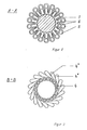
- the contact arrangement shown in FIG. 1 comprises a first contact piece 1 designed and movable with a circular cross section and a second, fixed contact piece 2.
- This contact piece 2 receives in its flange 3 contact fingers 4 which are circular and circular in cross section and which lie above the plane B - B are cranked in the tangential direction to the circle on which they are arranged, as can also be seen in FIG. 3.
- roller guides 5 are attached, which receive the contact rollers 6.
- the contact rollers 6 are pressed radially outwards. Because of the cranking of the contact fingers 4, they are subjected to torsion in the area between the cross-sectional plane BB and the clamping in the flange 3. The spring action is therefore not generated by a bending force, but by a torsional force.
- An annular clamping ring 7 is also provided in the area near the cranking point. This clamping ring ensures that all contact fingers 4 or the rollers 6 assigned to them come into contact with the contact piece 1 even when the two contact pieces 1 and 2 are axially offset.
- the contact fingers 4 with a circular cross-section in the area of the cranking point are designated by 4 'in FIG. 3. In this area, these contact fingers act as levers and convert the force exerted by the contact piece 1 on the contact rollers 6 into a torsional stress in the contact fingers 4 below the cranking point.
- the contact fingers 4 can also have a different one, e.g. square, cross-section. Even in the area of torsional stress, it is possible to use other cross-sections that deviate from the circular ring shape, e.g. elliptical cross sections.
- the contact arrangement according to the invention is characterized by small dimensions transversely to the conductor track and also has the great advantage, which is important in practice, that axial displacements of the two contact pieces 1 and 2, caused by manufacturing or assembly tolerances, are compensated for without loss of current carrying capacity.
Landscapes
- Contacts (AREA)
- Arc-Extinguishing Devices That Are Switches (AREA)
- Coupling Device And Connection With Printed Circuit (AREA)
Abstract
Description
- Die Erfindung betrifft eine steckbare Kontaktanordnung für die Verbindung von Geräten untereinander bzw. von Geräten und Schaltanlagenteilen für die Starkstromtechnik nach dem Oberbegriff des Anspruchs 1.
- Kontaktanordnungen für steckbare elektrische Verbindungen von elektrischen Geräten, Apparaten und/oder Schaltanordnungen, die aus zwei Kontaktstücken bestehen, die axial zueinander verschiebbar sind und mittels Gleitkontakten oder Rollenkontakten miteinander in Eingriff kommen, sind bereits bekannt (DE-A 12 525 082 bzw. DE-B-21 129 213).
- Rollenkontakte haben gegenüber Gleitkontakten den Vorteil, daß sie die zur Relativbewegung der Kontaktstücke notwendigen Kräfte reduzieren. Rollenkontakte sind rotationssymmetrisch gestaltete und drehbar gelagerte leitende Körper; sie sind in verschiedenen geometrischen Formen bekannt, z.B. als Kegelstumpf (DE-B 21 167 940), als Kugel (DE-B 21 205 172), als Kugelkalotte (DE-C 31 003 323), als paarweise auf einer Achse angeordnete Scheiben
- (DE-C 31 040 653) sowie als zylinderförmige Rollen (DE-B 21 216 968).
- Die Kontaktkraft, mit der das eine Kontaktstück auf das andere drückt, wird dabei meist mittels Stahlfedern, die als Spiralfedern oder Blattfedern ausgebildet sind, erzeugt (DE-B 21 167 946; DE-C 31 142 940). Wenn beträchtliche Kontaktkräfte zu übertragen sind, und eine größere Zahl von Rollenkontakten benötigt wird, weisen diese Anordnungen meist ungünstige radiale Abmessungen auf, die den Leiterabstand und damit die Größe der Geräte und Schaltanlagen nachteilig beeinflussen.
- Zur Überwindung dieser Nachteile sind auch schon Steckverbindungen bekannt geworden, bei denen die den elektrischen Strom führenden Teile zugleich auch zur Erzeugung der Kontaktkraft ausgenutzt werden (DE-B 21 145 254). Diese Teile sind fingerartig ausgebildet und als Kontaktfedern aus elektrisch gut leitendem Material, z.B. Kupferlegierungen, hergestellt. Sie tragen an ihrem Ende in Nuten vorgesehene Rollen, die in entsprechenden Nuten im beweglichen Kontakτstück in Eingriff
- kommen. Die auf Biegung beanspruchten Kontaktfedern vermögen aber nur eine undefinierte Kontaktkraft aufzubringen, weil diese in hohem Maße von der Länge des Biegebalkens abhängig ist. Tritt ferner durch Fertigungs- und/oder Montagetoleranzen bedingt ein Versatz der Achsen des beweglichen Konstaktstücks und des feststehenden Kontaktstücks auf, so führt dies dazu, daß nicht mehr alle Kontaktfinger an der Kontaktgabe beteiligt sind. Diese Anordnung ist für die genannten Zwecke als Steckverbindung auch deshalb ungeeignet, weil sie nur in einem definierten Abstand des beweglichen und des feststehenden Kontaktstücks zueinander zu einer sicheren Kontaktgabe führt.
- Es besteht daher das Bedürfnis nach Steckverbindungen, die günstige radiale Abmessungen aufweisen, große Ströme zu übertragen vermögen und zugleich den Montage- und Betriebsbedingungen gut entsprechen.
- Der Erfindung liegt mithin die Aufgabe zugrunde, eine Steckverbindung gemäß dem Oberbegriff des Anspruchs 1, die für die Übertragung großer Ströme geeignet ist, anzugeben, die große und gleichmäßig verteilte Kontaktkräfte erzeugt, und zwar unabhängig davon, ob ein radialer Versatz der zu verbindenden Kontaktstücke vorliegt. Die Steckverbindung soll darüber hinaus möglichst auch in der Lage sein, Toleranzen auch in axialer Richtung zwischen den Kontaktstücken auszugleichen.
- Diese Aufgabe wird durch die kennzeichnenden Merkmale des Anspruchs 1 gelöst. Vorteilhafte Ausführungsformen der erfindungsgemäßen Kontaktanordnung sind Gegenstand der Unteransprüche.
- Die erfindungsgemäße Kontaktanordnung besteht im wesentlichen aus einem im Querschnitt runden, elliptischen oder eckigen, stabartigen ersten Kontaktstück sowie einem zweiten, Kontaktfinger aufweisenden Kontaktstück. Bei diesem zweiten Kontaktstück sind die Kontaktfinger entsprechend der Kontur des ersten Kontaktstücks angeordnet; an dem einen Ende sind die Kontaktfinger in einem Kontaktstückteil befestigt, während sie an ihrem anderen Ende Gleitkontakte oder Rollenkontakte tragen. Beide Kontaktstücke sind relativ zueinander und axial verschiebbar. Durch eine solche Verschiebung können die beiden Kontaktstücke miteinander in Eingriff gebracht bzw. voneinander getrennt werden.
- Die erfindungsgemäße steckbare Kontaktanordnung ist vorzugsweise dort einsetzbar, wo Ströme von mehr als 630 A übertragen werden, und eine Unterbrechung des Leiterzuges, z.B. zur Revision der Anlage oder des elektrischen Geräts, gefordert wird. Die Kontaktanordnung gemäß der Erfindung ist ferner auch vorteilhaft einsetzbar, wo eine sichtbare Trennung eines Stromkreises zur Anzeige des Betriebszustandes gewünscht ist, z.B. als Teil eines elektrischen Trenners oder als Kontaktstrecke zwischen elektrischem Leistungsschalter und Schaltanlage, beispielsweise dort, wo der elektrische Leistungsschalter wenigstens teilweise aus der Anlage herausfahrbar ist.
- Anhand der Zeichnungen wird nachstehend ein Ausführungsbeispiel des Patentgegenstandes beschrieben. In der Zeichnung zeigen:
- Fig. 1 eine steckbare Kontaktanordnung mit einem Kontaktstück von kreisrundem Querschnitt und mit Rollenkontakten an den Kontaktfingern;
- Fig. 2 eine Draufsicht auf das Kontaktstück mit Kontaktfingern gemäß Fig. 1 in der Ebene A - A und
- Fig. 3 eine Schnittdarstellung des Kontaktstücks von Fig. 1 im Querschnitt in der Ebene B - B.
- Die in Fig. 1 dargestellte Kontaktanordnung umfaßt ein mit kreisrundem Querschnitt ausgeführtes und bewegliches erstes Kontaktstück 1 und ein zweites, feststehendes Kontaktstück 2. Dieses Kontaktstück 2 nimmt in seinem Flansch 3 im Querschnitt kreisrunde und kreisförmig angeordnete Kontaktfinger 4 auf, die oberhalb der Ebene B - B in Tangentialrichtung zu dem Kreis, auf dem sie angeordnet sind, gekröpft sind, wie sich auch aus Fig. 3 ergibt.
- Am Ende der Kontaktfinger 4 sind Rollenführungen 5 befestigt, welche die Kontaktrollen 6 aufnehmen. Wenn das erste, bewegliche Kontaktstück 1 mit dem zweiten, feststehenden Kontaktstück 2 in Eingriff kommt, werden die Kontaktrollen 6 radial nach außen gedrückt. Aufgrund der Kröpfung der Kontaktfinger 4 werden diese im Bereich zwischen der Querschnittsebene B - B und der Einspannung im Flansch 3 auf Torsion beansprucht. Die Federwirkung wird also nicht durch eine Biegekraft, sondern durch eine Torsionskraft erzeugt.
- Im Bereich nahe der Kröpfstelle ist ferner ein kreisringförmiger Spannring 7 vorgesehen. Dieser Spannring gewährleistet, daß auch bei axialem Versatz der beiden Kontaktstücke 1 und 2 alle Kontaktfinger 4 bzw. die ihnen zugeordneten Rollen 6 mit dem Kontaktstück 1 in Kontakt kommen.
- In den Fig. 2 und 3 sind gleiche Teile wie in Fig. 1 mit gleichen Bezugszahlen versehen.
- Zur Verdeutlichung sind die Kontaktfinger 4 mit kreisrundem Querschnitt im Bereich der Kröpfstelle in Fig. 3 mit 4' bezeichnet. In diesem Bereich wirken diese Kontaktfinger als Hebel und wandeln die vom Kontaktstück 1 auf die Kontaktrollen 6 ausgeübte Kraft in eine Torsionsbeanspruchung in den Kontaktfingern 4 unterhalb der Kröpfstelle um.
- Die Kontaktfinger 4 können erfindungsgemäß im Bereich der Rollenführungen 5 bzw. oberhalb der Kröpfstelle auch einen anderen, z.B. quadratischen,Querschnitt aufweisen. .Auch im Bereich der Torsionsbeanspruchung ist es möglich, andere, von der Kreisringform abweichende Querschnitte, z.B. elliptische Querschnitte, anzuwenden.
- Die erfindungsgemäße Kontaktanordnung zeichnet sich durch kleine Abmessungen quer zum Leiterzug aus und besitzt ferner den großen, für die Praxis wichtigen Vorteil, daß durch Fertigungs- oder Montagetoleranzen bedingte axiale Versetzungen der beiden Kontaktstücke 1 und 2 gegeneinander ohne Verluste an Stromtragfähigkeit kompensiert werden.
Claims (4)
dadurch gekennzeichnet ,
daß die Kontaktfinger (4)
Applications Claiming Priority (2)
| Application Number | Priority Date | Filing Date | Title |
|---|---|---|---|
| DD84271259A DD230107A1 (de) | 1984-12-20 | 1984-12-20 | Steckbare kontaktanordnung |
| DD271259 | 1984-12-20 |
Publications (2)
| Publication Number | Publication Date |
|---|---|
| EP0185840A2 true EP0185840A2 (de) | 1986-07-02 |
| EP0185840A3 EP0185840A3 (de) | 1988-04-06 |
Family
ID=5563704
Family Applications (1)
| Application Number | Title | Priority Date | Filing Date |
|---|---|---|---|
| EP85109339A Withdrawn EP0185840A3 (de) | 1984-12-20 | 1985-07-25 | Steckbare Kontaktanordnung |
Country Status (4)
| Country | Link |
|---|---|
| US (1) | US4696531A (de) |
| EP (1) | EP0185840A3 (de) |
| JP (1) | JPS61156608A (de) |
| DD (1) | DD230107A1 (de) |
Families Citing this family (3)
| Publication number | Priority date | Publication date | Assignee | Title |
|---|---|---|---|---|
| CN103854883B (zh) * | 2012-11-30 | 2015-12-30 | 施耐德电器工业公司 | 开关装置 |
| DE102016217673B4 (de) * | 2016-09-15 | 2020-06-04 | Te Connectivity Germany Gmbh | Elektrischer Kontakt für einen Steckverbinder, mit drehbaren Wälzkontaktkörpern und elektrische Steckverbindung mit einem solchen Kontakt |
| DE102016217667B4 (de) * | 2016-09-15 | 2020-04-02 | Te Connectivity Germany Gmbh | Elektrischer Kontakt mit Wälzkontaktkörpern an sich gegenüberliegenden Seiten sowie Steckverbindung mit einem solchen Kontakt |
Family Cites Families (3)
| Publication number | Priority date | Publication date | Assignee | Title |
|---|---|---|---|---|
| US1740640A (en) * | 1925-05-25 | 1929-12-24 | Ohio Brass Co | Electric switch |
| FR2415889A1 (fr) * | 1978-01-25 | 1979-08-24 | Bonhomme F R | Perfectionnements apportes aux douilles, pour dispositifs de contact electrique a fiche et douille, et a leurs procedes de fabrication |
| GB2065993A (en) * | 1979-12-04 | 1981-07-01 | Pa Management Consult | Electrical connector |
-
1984
- 1984-12-20 DD DD84271259A patent/DD230107A1/de not_active IP Right Cessation
-
1985
- 1985-07-25 EP EP85109339A patent/EP0185840A3/de not_active Withdrawn
- 1985-11-08 US US06/796,371 patent/US4696531A/en not_active Expired - Fee Related
- 1985-12-19 JP JP60284498A patent/JPS61156608A/ja active Pending
Also Published As
| Publication number | Publication date |
|---|---|
| US4696531A (en) | 1987-09-29 |
| EP0185840A3 (de) | 1988-04-06 |
| DD230107A1 (de) | 1985-11-20 |
| JPS61156608A (ja) | 1986-07-16 |
Similar Documents
| Publication | Publication Date | Title |
|---|---|---|
| EP2599165B1 (de) | Hochstromsteckverbinder | |
| EP3579348B1 (de) | Kontakthülse für einen elektrischen steckverbinder | |
| DE2923399C2 (de) | Verfahren zur elektrischen Verbindung eines Koaxialkabels und Anschlußarmatur für Koaxialkabel | |
| DE69105673T2 (de) | Transformator. | |
| EP2903103B1 (de) | Bürsteneinheit mit einer elastischen Bürste | |
| DE202007008847U1 (de) | Koaxialsteckverbinder | |
| EP3242359A1 (de) | Kabel | |
| DE69328662T2 (de) | Filterverbinder hoher Dichte | |
| EP2273623B1 (de) | Leistungsteil für einen Motor eines Flurförderzeugs | |
| DD269496A5 (de) | Schneidklemm-huelsenkontakt | |
| DE3734667C1 (en) | Cable end plug | |
| DE10261521B3 (de) | Hochstromführende Kontaktelemente mit Versatzausgleich | |
| WO2018153405A1 (de) | Steckverbindermodul mit federbrücken | |
| EP0185840A2 (de) | Steckbare Kontaktanordnung | |
| EP4053869A1 (de) | Schalter, insbesondere schnappschalter | |
| WO1998043321A1 (de) | Steckerbuchse mit in der form eines hyperboloids angeordneten kontaktbereichen | |
| BE1014553A3 (de) | Kontaktanordnung fur gleit-und steckkontakte elektrischer gerate und anlagen, insbesondere der elektrischen energietechnick, sowie steuer-und regelungstechnik. | |
| CH660814A5 (de) | Elektrischer leistungsschalter. | |
| DE3815555A1 (de) | Anschlussklemmenteil eines stoerung unterdrueckenden hochspannungs-widerstandsleiters | |
| DE202019105429U1 (de) | Kontaktvorrichtung zum Herstellen einer elektrisch leitenden Steckverbindung mit einem Kontaktelement | |
| EP4231466A1 (de) | Steckverbinder und steckverbindersystem | |
| DE2933042C2 (de) | Koaxial-Steckverbindung | |
| DE1003311B (de) | Steckverbindung | |
| DE3045206A1 (de) | Schubtrennschalter fuer mittelspannungs- und hochspannungs-schalt- und -verteileranlagen | |
| DE2601429B2 (de) | Koaxialkabel-Anschlußklemme |
Legal Events
| Date | Code | Title | Description |
|---|---|---|---|
| PUAI | Public reference made under article 153(3) epc to a published international application that has entered the european phase |
Free format text: ORIGINAL CODE: 0009012 |
|
| AK | Designated contracting states |
Kind code of ref document: A2 Designated state(s): AT CH DE FR LI NL SE |
|
| PUAL | Search report despatched |
Free format text: ORIGINAL CODE: 0009013 |
|
| AK | Designated contracting states |
Kind code of ref document: A3 Designated state(s): AT CH DE FR LI NL SE |
|
| RHK1 | Main classification (correction) |
Ipc: H01R 13/115 |
|
| 17P | Request for examination filed |
Effective date: 19880509 |
|
| STAA | Information on the status of an ep patent application or granted ep patent |
Free format text: STATUS: THE APPLICATION IS DEEMED TO BE WITHDRAWN |
|
| 18D | Application deemed to be withdrawn |
Effective date: 19900201 |
|
| RIN1 | Information on inventor provided before grant (corrected) |
Inventor name: GROSSMANN, STEFFEN, DIPL.-ING. Inventor name: LOEBL, HELMUT, DR.-ING. Inventor name: BOEHME, HELMUT, PROF. DR. SC. TECHN. |