EP0186210A2 - Senseur d'ions - Google Patents
Senseur d'ions Download PDFInfo
- Publication number
- EP0186210A2 EP0186210A2 EP85116605A EP85116605A EP0186210A2 EP 0186210 A2 EP0186210 A2 EP 0186210A2 EP 85116605 A EP85116605 A EP 85116605A EP 85116605 A EP85116605 A EP 85116605A EP 0186210 A2 EP0186210 A2 EP 0186210A2
- Authority
- EP
- European Patent Office
- Prior art keywords
- ion
- sensor according
- film
- group
- carrier substance
- Prior art date
- Legal status (The legal status is an assumption and is not a legal conclusion. Google has not performed a legal analysis and makes no representation as to the accuracy of the status listed.)
- Granted
Links
Images


Classifications
-
- G—PHYSICS
- G01—MEASURING; TESTING
- G01N—INVESTIGATING OR ANALYSING MATERIALS BY DETERMINING THEIR CHEMICAL OR PHYSICAL PROPERTIES
- G01N27/00—Investigating or analysing materials by the use of electric, electrochemical, or magnetic means
- G01N27/26—Investigating or analysing materials by the use of electric, electrochemical, or magnetic means by investigating electrochemical variables; by using electrolysis or electrophoresis
- G01N27/28—Electrolytic cell components
- G01N27/30—Electrodes, e.g. test electrodes; Half-cells
- G01N27/333—Ion-selective electrodes or membranes
- G01N27/3335—Ion-selective electrodes or membranes the membrane containing at least one organic component
Definitions
- the present invention relates to an ion sensor and, more particularly, to an ion sensor of the type wherein an ion concentration in a solution is measured by an electrode potential response.
- Conventional ion sensors of the type wherein an ion concentration in a solution is measured by electrode potential response include various ion sensors such as a hydrogen ion sensor, a potassium ion sensor, a calcium ion sensor, a sodium ion sensor, or a chloride ion sensor.
- glass electrodes are widely used, wherein a standard solution having a stable pH and a stable chloride activity is held with an internal reference electrode (Ag/AgCl electrode) in a standard liquid chamber formed by a glass membrane.
- the sensor is dipped in a sample_solution, and the pH value in the sample solution can be measured by the potential difference of both reference electrode between in the internal standard and the outer sample solutions.
- the glass membrane can be easily damaged or contaminated and their use in alkaline solutions is limited.
- a highly viscous solution containing an adsorbing substance e.g., blood
- the measurement precision is degraded within a short period of time. In order to prevent this degradation, substances attached to the glass membrane must be removed every 30 minutes during measurement.
- the glass type electrode has a standard internal solution chamber, it cannot be reduced in size beyond a certain limit.
- a pH sensor of the type using a hydrogen ion carrier film in place of a glass membrane is disclosed in, e.g., U.S. Patent No. 3,743,558, Japanese Patent Disclosure No. 47-7549, and J. Appl. Physiology 40, 14.
- the hydrogen ion carrier film is obtained by adding a hydrogen ion carrier substance in a polymer film and hydrogen ions from the inner solution permeate the film to reach a reference electrode so as to measure the hydrogen ion concentration.
- the carrier film components tend to elute, presenting a problem of poor measurement reproducibility.
- an object of the present invention to provide an ion sensor of a solid film type which does not require a standard liquid chamber, wherein a concentration of a specific type of ions is measured by the potential response.
- an ion sensor of the type wherein a specific type of ions in a solution is measured by a potential response comprising:
- the reversible redox polymer is derived by electrooxidation polymerization of an amino aromatic compound and/or a hydroxy aromatic compound.
- reversible redox polymer is intended to indicate polymers having a reversible oxidation/reduction function and include those which undergo an oxidation/reduction reaction of a quinone-hydroquinone type and those which undergo an oxidation/reduction reaction of an amine-quinoid type.
- the "polymer” includes both a homopolymer and an interpolymer such as a copolymer.
- an ion sensor 10 has an electrically conductive base 11.
- the base 11 can consist of a noble metal such as platinum, gold, silver or palladium. or conductive carbon such as basal plane pyrolytic graphite, or glassy carbon. Basal plane pyrolytic graphite (BPG) is particularly preferable as the material of the base 11.
- BPG Basal plane pyrolytic graphite
- a surface portion of the base 11 on which a film having an oxidation/reduction function to be described later is formed can be covered with a semiconductor material such as indium oxide or tin oxide.
- a solid film 13 of a reversible redox polymer is directly formed on an end face lla of the base 11.
- the solid film 13 undergoes the reversible oxidation/reduction reaction and generates a specific potential in the conductive base 11.
- The-specific potential generated in the base 11 in this manner corresponds to the ion concentration.
- the oxidation/reduction reactions of the redox polymer films are the reversible oxidation/reduction reaction of quinone-hydroquinone.type represented by the general formula: (wherein R and R' are polymer structures). and the reversible oxidation/reduction reaction of an amine-quinoid type represented by the general formula: (wherein R and R' are polymer structures).
- Compounds capable of forming redox polymers which undergo the oxidation/reduction reaction of a quinone-hydroquinone type include hydroxy aromatic compounds and nonhydroxy quinone compounds.
- the hydroxy aromatic compounds can be represented by general formula (I): (wherein Ar is an aromatic nucleus, each R U is a substituting group, m is 1 to an effective valency of Ar, and n is 0 to (effective valency of Ar - 1).
- the aromatic nucleus Ar can be a monocyclic ring such as a benzene nucleus. a polycyclic ring (condensed ring) such as an anthracene nucleus, a pyrene nucleus, a chrysene nucleus, a perylene nucleus, or a corpnene nucleus. or a heterocyclic ring.
- the substituting group R 0 can be an alkyl group such as methyl group.
- hydroxy aromatic compounds may include phenol, 3,5-, 2,6- and 3,4-xylenols, 2-hydroxypyridine, o- and m-benzylalcohols, o-, m- and p-hydroxybenzaldehydes, o-, m- and p-hydroxyacetophenones, o-, m- and p-hydroxypropiophenones, o-, m- and p-benzophenols, o-, m- and p-hydroxybenzophenones, o-, m- and p-carboxyphenols, diphenylphenol, 2-methyl-8-hydroxyquinoline, 5-hydroxy-1,4-naphthoquinone, 4-(p-hydroxyphenyl)-2-butanone, 1,5-dihydroxy-1,2,3,4-tetrahydronaphthalene, bisphenol A, sal
- Examples of the quinone compound containing no hydroxyl group may include 1,6-pyrenequinone, phenanthrenequinone, 1-aminoanthraquinone, purpurin, and anthrarufin.
- the compounds for forming redox polymer films capable of the oxidation/reduction reaction of amine-quinoid type are aromatic primary amines represented by the following general formula (II): (wherein Ar, R 0 , m and n have the same meanings as in formula (I) above).
- aromatic primary amines may include aniline, 1-aminopyrene, 1,2-, 1,6-and 1,8-diaminopyrenes, 1-aminochrysene, 1,4-diaminochrysene, 1- and 9-aminophenanthrenes, 9,10-diaminophenanthrenes, 1-aminoanthraquinone, p-phenoxyaniline, o-phenylenediamine, p-chloroaniline, 3,5-dichloroaniline, 2,4,6-trichloroaniline, and N-phenyl-p-phenylenediamine.
- aromatic secondary amines such as N-methylaniline may also be used.
- hydroxy aromatic compounds, amino-containing compounds and quinone compounds as described above may be referred to as monomers herein.
- monomers 2,6-xylenol and 1-aminopyrene are particularly preferable.
- Redox polymer films of at least one monomer selected from those enumerated above can be formed on the end faces lla of the base 11 by various methods.
- a selected monomer is directly polymerized on the surface of the base 11 by electrooxidation polymerization or electrolytic precipitation.
- a selected monomer is polymerized by irradiation with an electron beam or. light or by application of heat.
- the base 11 is dipped in a solution obtained by dissolving the resultant polymer in a solvent, and drying coated polymer.
- a polymer is prepared and is directly fixed on the surface of the base 11 by chemical, physical or radiation treatment.
- the method of directly coating a redox polymer by electrooxidation polymerization is preferable.
- At least one type of monomer is dissolved in a solvent containing a supporting electrolyte.
- the base 11 and a reference electrode e.g., a sodium chloride saturated calomel electrode (SSCE) are dipped in the resultant solution.
- SSCE sodium chloride saturated calomel electrode
- electrooxidation polymerization of the monomer takes place to precipitate a film.
- the solvent which may be used in such electrooxidation polymerization may include acetonitrile, water, dimethylformamide, dimethylsulfoxide, and propylene carbonate.
- Examples of the supporting electrolyte may include sodium perchlorate, sulfuric acid, sodium sulfate, boric acid, tetrafluoro potassium phosphate, and quaternary ammonium salts.
- Electrooxidation polymerization is preferably performed by adding a catalytic amount (e.g., 1 mM to 100 mM. preferably 10 to 30 mM) of pyridine.
- a redox polymer derived by electrooxidation polymerization is dense and does not allow permeation of oxygen molecules even if the polymer film is thin.
- the redox polymer film 13 does not preferably change its potential depending upon the partial oxygen gas content in an aqueous solution.
- a redox polymer derived from any of the monomers enumerated above has this property.
- the redox polymer film 13 preferably has a thickness of 0.1 ⁇ m to 0.2 mm. When the film thickness is smaller than 0.1 ⁇ m, desired redox properties are not obtained. If the film thickness exceeds 0.2 mm, the film resistance is undesirably increased..
- the redox polymer film according to the present invention can be impregnated with an electrolyte.
- the charge transfer rate of the film is increased, the film resistance is reduced and conductivity of the film is increased.
- a suitable electrolyte for impregnation is selected, the charge transfer resistance at the interface between-the redox-polymer film and the carrier film can be decreased. Dissolution diffusion of the redox polymer in the carrier film can also be prevented.
- Examples of the electrolyte for impregnation of the redox polymer may include phosphoric acid, dipotassiumhydrogenphosphate, sodium perchlorate, sulfuric acid, tetrafluoroborate, and tetraphenylborate.
- the base 11 is dipped in a solution of the selected electrolyte.
- the electrolyte is impregnated in an amount by weight of about 10 -6 to 10 -1 based on the weight of the redox polymer film.
- the impregnation amount is preferably 10 -3 to 10 - 1 .
- the redox polymer film is formed on the surface of the redox polymer film 13.
- the ion carrier film 14 consists of a film forming polymeric material and an ion carrier substance.
- the ion sensor of the present invention constitutes a sensor of ions of a type in accordance with the type of ion carrier substaoce contained in the film 14.
- a hydrogen ion carrier substance when used, a hydrogen ion sensor is obtained.
- a potassium ion sensor is obtained with a potassium ion carrier substance, a sodium ion sensor with a sodium ion carrier substance, a calcium ion sensor with a calcium ion carrier substance, a chloride ion sensor with a chloride ion carrier substance, and a hydrogencarbonate ion sensor with a hydrogencarbonate ion carrier substance.
- Examples of the hydrogen ion carrier substance may include alkylamines represented by: (wherein each of R 1 , R 2 and R 3 is an alkyl group, at least two of which are alkyl groups having 8 to 18 carbon atoms and preferably 10 to 16 carbon atoms), and pyridine derivatives represented by: (wherein R 4 is an alkyl group having 8 to 18 carbon atoms and preferably 10 to 16 carbon atoms).
- Examples of the amine represented by the general formula (A) may include tri-n-dodecylamine, tri-n-decylamine, tri-n-octylamine, di-n-dodecyl-n-decylamine, and di-n-todecyl-n-octylamine.
- Examples of the amine represented by the general formula (B) may include 3-hydroxy-N-dodecylpicolineamide, 3-hydroxy-N-decylpicolineamide, and 3-hydroxy-N-octyl- picolineamide.
- Tridodecylamine and 3-hydroxy-N-dodecylpicolineamide is preferable as a hydrogen ion carrier substance.
- potassium ion carrier substance may include valinomycin, bis(crown ether) (eg. bis[(benzo-15-crown-5)-4'-methyl]pimelate, bis[(benzo-15-crown-5)-4'-methyl]oxide), nonactin, monactin, and crown ethers (e.g., dibenzo-18-crown-6, dibenzo-15-crown-5, dibenzo-30-crown-10, and dicyclohexyl-18-crown-6).
- valinomycin and bis[(benzo-15-crown-5)-4'-methyl]pimelate are particularly preferable.
- sodium ion carrier substance may include bis[(12-crown-4)methyl]dodecylmalonate, N,N,-N,N-tetrapropyl-3,6-dioxanate-diamide, 3-methoxy-N,N,N,N-tetrapropyl-1,2-phenylenedioxydiacetoamide, (-)-(R,R)-4,5-dimethyl-N,N,N,N-tetrapropyl-3,6-dioxaoctanediamide, 4-methyl-N,N,N,N-tetrapropyl-3,6-dioxaoctanediamide, N,N,N,N-tetrapropyl-1,2-phenylenedioxydiacetoamide, N,N,N,N-tetrapropyl-2,3-naphtharenedioxydiacetoamide, 4-t-butyl-N,N,N,N-N-
- Examples of the calcium ion carrier substance may include calcium-bis- di-(n-octylphenyl) phosphate, (-)-(R,R)-N, N'-bis[(11-ethoxycarbonyl)undecyl]-N,N'-4,5-tetramethyl-3,6-dioxaoctanediamide, and calcium[bis di(n-decyl)phosphate]. Calcium-bis[di(n-octylphenyl) phosphate] is particularly preferable.
- chloride ion carrier substance may include quaternary ammonium salts represented by the general formula: (wherein each of R 5 , R 6 , R and R 8 is independently an alkyl group having 6 to 18 carbon atoms, and one of R to R 8 can contain a hydrogen atom or a methyl group), and triphenyl tin chloride represented by:
- Examples of the quaternary ammonium salts represented by general formula (C) above may include tetraoctylammonium perchlorate, methyltri-n-decylammonium perchlorate, methyltri-n-dodecylammonium perchlorate, methyltri-octylammonium perchloride, methyltri-n-ammonium perchlorate, and n-tetrahexylammonium perchlorate.
- Particularly preferable chlorine ion carrier substances are tetraoctylammonium perchlorate, methyltri-n-decylammonium perchlorate, and methyltri- dodecylammonium perchlorate.
- Examples of the hydrogencarbonate ion carrier substance may include a quaternary ammonium salt of the formula: where R 9 to R 11 are independently alkyl groups having 8 to 18 carbon atoms and X - is Cl - , Br - or OH - ; a tertiary amine of the formula where R 12 is phenyl group, methyl group or hydrogen atom, R 13 is hydrogen atom or methyl group, and R 14 is hydrogen atom, methyl group or octadecyl group; and the compounds of formulas: and
- Each ion carrier substance is preferably used in an amount of 0.1 to 15.0 parts by weight based on 100 parts by weight of the ion carrier film.
- the ion carrier film conveniently contains an electrolyte salt in addition to an ion carrier substance.
- An electrolyte salt serves to enhance the ion transfer in a plasticizer solution.
- a second effect of the electrolyte salt increases the conductivity of the carrier and decreases the film resistance, and prevents permeation of charges of opposite polarity in the solution to the film.
- Examples of the electrolyte salt contained in the ion carrier film may include sodium tetrakis(p-chlorophenyl)borate, potassiumtetrakis(p-chlorophenyl)borate; and compounds represented by general formulas: and (wherein each R is independently an alkyl group and preferably an alkyl group having 2 to 6 carbon atoms).
- Examples of the compound represented by general formula (F) may include compounds wherein R 15 is an alkyl group having 1 and 10 carbon atoms. At least one of tetraalkyls can be a methyl group.
- Examples of the compound represented by general formula (G) may be compounds wherein R 15 is an alkyl group having 1 and 10 carbon atoms. At least one of tetraalkyls can be a methyl group.
- An electrolyte salt is preferably contained in an amount of 0.05 to 3.0 parts by weight in the ion carrier film.
- the polymeric material of the film 14 carries an ion carrier substance and an electrolyte salt and fixes them to the redox polymer film 13.
- the polymeric material must be able to form a film.
- examples of such a polymeric material may include polyvinyl chloride, a vinyl chloride-ethylene copolymer, polyester, polyacrylamide, polyurethane, and silicone resin.
- polyvinyl chloride may be mixed with a plasticizer such as dioctyl sebacate, dioctyl maleate, dioctyl adipate, and bis(2-ethylnexyl) sebacate.
- polyvinyl chloride is preferable due to high film formability.
- Polyvinyl chloride is preferably in a paste form.
- Paste polyvinyl chloride stably carries an ion carrier substance and firmly adheres to the surface of the base without separation.
- Paste polyvinyl chloride has a short solidification time of 5 minutes or less and allows easy film formation.
- Paste polyvinyl chloride is obtained by adding 50 to 500 parts by weight of a plasticizer to 100 parts by weight of polyvinyl chloride.
- a polymeric substance, ion carrier substance, an electrolyte, and a plasticizer, if required, are dissolved in a solvent, e.g., tetrahydrofuran.
- a solvent e.g., tetrahydrofuran.
- an ion sensor has an electromotive force (E) generated in the conductive base 11 which linearly changes in accordance with the concentration of a specific type of ions in an aqueous solution.
- E electromotive force
- the linear relationship between the E value and the ion concentration (e.g., pH value in the case of hydrogen ions), more specifically, the slope (e.g., mV/pH) of the line is more approximate to the theoretical value (59.16 mV at 25°C) when the film 14 has a larger thickness.
- the film 14 has a thickness of 200 ⁇ m to 10 mm. Changes in electromotive force with a thickness falling within this range are small.
- the response time (time required for the electromotive force to reach a predetermined value) is slightly prolonged as the thickness of the ion carrier film is increased. However, no actual problem is encountered if the thickness of the film 14 remains within the above range. When the thickness of the film 14 remains within this range, the response time is very short.
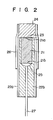
- Fig. 2 shows the detailed construction of the ion sensor according to the present invention.
- a redox polymer film 23 is formed on one end face 21a of a base 21 of a conductive material.
- the base 21 is inserted into an insulating tube 22a such that one end 21a of the base 21 coincides with that of the tube 22a.
- the base 21 is a wire having a diameter of, e.g.,'0.25 to 5.0 mm.
- a leading wire 27 is connected to the other end 21b of the base 21 by a conductive adhesive 25.
- An insulating resin 22b is filled in the tube 22a including the gap between the base 21 and the tube 22a.
- An insulating tube 26 covers the tube 22a so as to project from the base 21.
- An ion carrier film 24 is formed on the projecting portion of the tube 26 so as to be in direct contact with the redox polymer film.
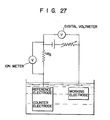
- an ion sensor 10 of the present invention is dipped together with a reference electrode 33 such as a saturated calomel electrode in an aqueous solution 32 to be measured held in a container 31.
- the ion sensor 10 and the reference electrode 33 are connected to a potentiometer 34.
- the specific type of ions in the solution are immediately permeated to a redox polymer film 13 through an ion carrier film 14.
- the film 13 undergoes the oxidation/reduction reaction and generates an electromotive force corresponding to the concentration of the specific type of ions.
- the electromotive force generated is measured by the potentiometer 34 as a difference with respect to the reference electrode 33.
- the electromotive force of the ion sensor of the present invention has a linear relation (Nernst equation) with the ion concentration. Thus, the concentration of the specific type of ions in the solution can be measured.
- a surface of a disk (diameter: 5 mm; length: 5 mm) consisting of basal plane pylolytic graphite (BPG) was cleaved by a sharp cutter to expose a new surface.
- the outer circumferential surface of the disk base was covered with a heat shrinkable tube for insulation, and mercury was charged into the tube to connect the base and a leading wire.
- This BPG disk was used as a working electrode
- SSCE saturated sodium chloride calomel electrode
- a platinum net was used as a counter electrode.
- Electrooxidation polymerization was performed in a three electrode electrolysis cell under the conditions presented below so as to form an electrooxidation polymer film on the exposed surface of the base.
- An electrolytic solution was obtained by adding 10 mM/I of 1-aminopyrene (AP) and 10 mM/I of pyridine to an acetonitrile solvent containing 0.1 M/l of sodium perchlorate as a supporting electrolyte. After sweeping the potential of the working electrode at a speed of 50 mV/sec within a range of 0 V to +1.0 V (with reference to the SSCE) three times, constant potential electrolysis was performed at + 1 .0 V (with reference to the SSCE) for 10 minutes. Thus, an electrooxidation polymer film (oxidation/reduction film) of 1-aminopyrene was formed on the surface of the base.
- the polymer film was rinsed with water and was stored in a phosphate buffer solution, having a pH of 6.86, for one day so as to stabilize the oxidation/reduction potential of the oxidation/reduction film.
- a hydrogen ion carrier film was formed by the following method.
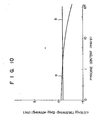
- the equilibrium potentials obtained by the sensor in each different solution and the pH were measured .using the pH sensor prepared in Example 1 and an SSCE as a reference electrode.
- the solutions measured were cow's blood (Test Example 1), standard serum (Versatol A, General Giagotics der Werner-Lambert Inc.) (Test Example 2), a lactic acid Ringer solution (composition: 0.6% (w/v) of sodium chloride, 0.03% (w/v) of potassium chloride, and 0.31% (w/v) of lactic acid; electrolyte components: 131 mg/l of Na + , 4 mg/l of K + , 3 mg/l of Ca 2+ , 110 mg/l of Cl, and 28 mg/l of lactate) (Test Example 3), a solution obtained by adding 5% (w/v) of dextran to 0.1 M/l physiological saline solution (Test Example 4), a bioelectrolyte solution ("HICALIQ" available from TERUMO; composition: dex
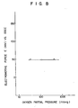
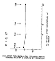
- the influence of the oxygen partial pressure on the equilibrium potential was measured using the pH sensor prepared in Example 1 and changing the oxygen partial pressure within a range of 47 mmHg to 630 mmHg with a standard phosphate buffer solution having a pH of 6.86.
- the measurement temperature was 37°C+0.1°C.
- the obtained results are shown in Fig. 8. It is seen from these results that the pH sensor is not affected by the oxygen partial pressure.
- a pH sensor was prepared following the same procedures as in Example 1 except that tetrabutylammonium tetrafluoroborate was used in place of sodium perchlorate as a supporting electrolyte.
- a pH sensor was prepared following the same procedures as in Example 1 except that carbon fiber ("HTA-7W-100" available from Toho Rayon; resistibility: about 1.5 x 10 -3 ⁇ cm; cross-sectional area: 3.8 x 10 -4 cm 2 ) was used in place of basal plane pyrolytic graphite (Example 3).
- Another pH sensor was similarly prepared by using BPG having a diameter of 0.5 mm (Example 4).
- a pH sensor was prepared following the same procedures as in Example 1 except that 1-aminoanthracene was used in place of 1-aminopyrene.
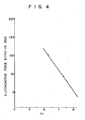
- the line had a slope of 56 mV/pH within a pH range of 5.15 to 8.20.
- pH ion sensors were prepared following the same procedures except that trioctylamine (Example 6) and tridecylamine (Example 7) were used in place of tri-n-dodecylamine when a hydrogen ion carrier film was coated.
- Test Example 13
- pH sensors were prepared following the same procedures as in Example 1 except that platinum (Example 8), palladium (Example 9), indium oxide (Example 10), and silver (Example 11) were used in place of BPG for bases and electrooxidation polymerization was performed under the conditions indicated in Table 2 below.
- a pH sensor was prepared following the same procedures as in Example 1 except that sodium sulfate or sulfuric acid of 0.5M concentration containing 10 mM p-phenoxyaniline as an electrolyte was used for electrooxidation polymerization.
- pH electrodes were prepared following the same procedures as in Example 1 except that AP electrooxidation polymerization was performed under the conditions shown in Table 4 below:
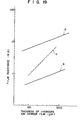
- Figs. 9 and 10 show the relationship between the pyridine content in AP electrooxidation polymerization and the value AE (the E value at the saturated oxygen partial pressure minus the E value at the dissolved oxygen partial pressure under air (25°C)).
- AE the E value at the saturated oxygen partial pressure minus the E value at the dissolved oxygen partial pressure under air (25°C)
- hollow dots correspond to Test Examples 16 to 20, while solid dots correspond to Test Examples 21 to 25.
- curve a corresponds to Test Examples 26 to 30, while curve b corresponds to Test Examples 31 to 35.
- the value AE is small and the equilibrium potential is stable in the order of TBABF 4 -THF system, TBABF 4 -CH 3 CN system, NaClO 4 -THF system, NaCf0 4 -CH 3 CN system.
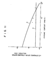
- Figs. 11 and 12 show the relationship between the pyridine content and the difference between the E value in standard serum and the E value in the standard solution (phosphate buffer solution).
- curve a corresponds to Test Examples 16 to 20
- curve b corresponds to Test Examples 21 to 25.
- curve a corresponds to Test Examples 26 to 30, and curve b corresponds to Test Examples 31 to 35. From the above results, it_is seen that the above-mentioned difference is small in the order of NaClO 4 -CH 3 CN system, TBABF 4 -CH 3 CN system, TBABF 4- THF system, NaClO 4 -THF system.
- the supporting electrolyte is TBABF 4
- the difference is not dependent on the pyridine content and is substantially constant.
- the response time is short in the order of NAClO 4 -THF system, NaClO 4 -CH 3 CN system, TBABF 4 -CH 3 CN system, TBABF 4 -THF system.
- AP electrooxidation polymerization was performed in a three electrode cell using the partially insulated BPG disk as a working electrode, an SSCE as a reference electrode and a platinum net as a counter electrode.
- the electrolytic solution used was an acetonitrile solution containing 0.1M sodium perchlorate, 10mM of AP and 10 mM of pyridine.
- Electrolysis was performed by constant potential electrolysis for 10 minutes at +1.0 V (with reference to the SSCE; this will be the same in the following description) after the potential of the working electrode was swept three times from 0 V to +1.0 V with reference to the SSCE. After the electrolysis, the working electrode was washed with water and dried. The film formed under these electrolysis conditions had a thickness of about 50 ⁇ m.
- Each electrode obtained in this manner was immersed in an electrolytic solution shown in Table 6 for 48 hours, washed with water, dried and coated with a hydrogen ion carrier film as in Example 1.
- the film thickness was about 600 ⁇ m.
- An electrode was prepared by forming a hydrogen ion carrier film of about 400 ⁇ m thickness following the same procedures as in Example 33 except that the solution used for forming the hydrogen ion carrier film had the following composition.
- the sensor characteristics of the resultant electrode were examined.
- the step response in solutions having different pHs and the difference of electrode potential between a standard phosphate buffer solution and a standard serum having the same pH were examined.
- the obtained results are shown in Table 7. (Solution Composition)
- the Nernst's plot had a slope of about -59 mV and the sensor characteristics were good within a KTpC f PB concentration range of 0 to 0.064% by weight.
- step response is slow.
- the KTpClPB concentration exceeds 0.18% by weight, the Nernst's plot has a slope of almost_O and the carrier substance does not exhibit its function, providing an impractical sensor.
- the difference (Es - Ep) slightly changed in accordance with change in the KTpClPB concentration.
- An electrode was prepared by forming a hydrogen ion carrier film having a thickness of about 300 to 400 ⁇ m following the same procedures as in Example 38 except that the solution for forming the hydrogen ion carrier film had a composition as shown below. The sensor characteristics and so on of the resultant electrode were examined. The obtained results are shown in Table 8.
- a copper wire as a leading wire was adhered to one end face (surface area: 7.85 x 1 0 -3 cm 2 ) of a small piece (diameter: 1.1 mm; length: 5.0 mm) of basal plane pyrolytic graphite (BPG) as a conductive base using a conductive adhesive ("C-850-6" available from Amicon K.K.)
- BPG basal plane pyrolytic graphite
- C-850-6 available from Amicon K.K.
- Electrooxidation polymerization was performed in a three electrode cell under the following conditions using the base prepared in this manner as a working electrode, a saturated sodium chloride calomel electrode (SSCE) as a reference electrode, and a platinum mesh as a counter electrode. An electrooxidation polymer film was formed on an exposed surface of the base.
- SSCE saturated sodium chloride calomel electrode
- An electrolytic solution used was obtained by adding 10 mM/l of 1-aminopyrene and 10 mM/I of pyridine to an acetonitrile solvent containing 0.1 M/1 of sodium perchlorate as a supporting electrolyte. After the working electrode potential was swept three times at a sweeping speed of 50 mV/sec within a potential range of 0 to +1.0 V (with reference to the SSCE), constant potential electrolysis was performed at +1.0 V for 10 minutes. In this manner, an electrooxidation polymerization film of 1-aminopyrene (oxidation/reduction film) was formed on the exposed surface of the base.
- the solution was filled in the gap after deaeration at a reduced pressure of 10 -1 to 10 -2 mmHg for about 10 hours.
- the pH sensor of the present invention was prepared in this manner. Total thickness of oxidation/reduction film and hydrogen ion carrier film was 1 mm.
- E 0 was 482.0 mV and the value corresponding to (RT/F) was 61.4 mV (38.5°C).
- the pH can be calculated by the following equation (2) in accordance with the equilibrium potential E of the pH sensor:
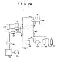
- the blood pH of the dog (mixed breed; weight: 25 kg) was continuously measured in an extracorporeal blood circuit outside the body of the dog for 17 hours.
- blood sampled from the carotid (artery) of a dog 41 was circulated through a polyvinyl chloride tube 42 (inner diameter: 8.0 mm) via a flow meter 43, a roller pump 44, a heat exchanger 45 and hollow fiber-type oxygenator 46 (four units each having a total membraoe area of 0.5 m 2 ; corresponding to an oxygen gas flow rate of 0.5 l/min), and oxygenized blood was returned to the artery of the dog.
- the blood flow rate (flow direction is indicated by arrows) was 1.2 l/min, and the extracorporeal blood temperature was kept at 38.5°C by the heat-excnanger 45.
- a pH sensor'10 (one prepared in Example 40) of the present invention, a reference electrode (SSCE) 53 and a temperature sensor 47 were inserted into the tube 42 at the carotid artery side such that each extended at its distal end into the tube 42 by about 1 mm.
- the pH sensor 10 and the reference electrode 53 were connected to a potentiometer 54.
- the potentiometer 54 and the temperature sensor 47 were connected to a computer 49 ("FM-li" available from FUJITSU) through a GP-IB interface adapter 48.
- the computer 49 was used to calculate the pH in accordance with equation (2) above. The calculated result was displayed on a display device 50.
- the pH of blood was measured together with the blood carbon dioxide gas partial pressure and the oxygen gas partial pressure by a blood gas meter "BMS-MK-2" available from Radiometer Inc. (capable of measuring the blood gases and pH). Since the blood gas meter could only measure the pH at 37°C, the measured pH was corrected by the following equation (3): (wherein pHm is the pH (37°C) measured by the blood gas meter described above, and t is the temperature of the dog blood (38.5°C),to obtain a pH at 38.5°C.
- a pH sensor of the shape as shown in Fig. 2 was prepared by the following method.
- a column having a diameter of 1.3 mm was cut off from a plate of basal plane pyrolytic graphite (BPG) (available from Union Carbide Corp.)
- BPG basal plane pyrolytic graphite
- a leading wire 27 was connected to a bottom surface 21b of the column with a conductive adhesive 25 ("C-850-6" available from Amicon K.K.)
- C-850-6 available from Amicon K.K.
- the structure was inserted into a teflon tube 22a having a diameter of 1.7 mm, and an insulating material 22b ("TB2067" available from Three Bond Inc.) was filled for electrical insulation.
- a distal end 21a of an electrode of the thus obtained BPG base 21 was cleaved by a knife blade to expose a new surface.
- a saturated sodium chloride calomel electrode (SSCE) as a reference electrode and a platinum mesh as a counter electrode electrooxidation polymerization was performed under the following conditions to form an oxidation/reduction polymer film 23 on the surface of the base distal end face 21a.
- SSCE saturated sodium chloride calomel electrode
- the electrolytic solution was an acetonitrile solution which contained 0.2 M/l of sodium perchlorate as a supporting electrolyte and 0.5 M/l of 2,6-dimethylphenol (2,6-xylenol) as a monomer.
- Electrooxidation polymerization was performed by sweeping the electrolysis voltage within a range of 0 V_to 1.5 V (with reference to the 'SSCE) at a sweeping speed of 50 mV/sec three times, and then performing constant potential electrolysis at 1.5 V for 10 minutes.
- a film formed in this manner (dark blue in a dry state) was washed with methanol (the film color changed to orange), and was thereafter dipped in a phosphate buffer solution having a pH of 7.4 so as to stabilize the potential of the oxidation/reduction film.
- the oxidation/reduction film electrode was rinsed with water, it was dried and a hydrogen ion carrier film was formed thereover in the following manner.
- a coating solution A was prepared by dissolving in 10 ml of tetrahydrofuran (THF) 25.6 mg of tri-n-dodecylamine (TDDA) as a hydrogen ion carrier, 5.7 mg of potassiumtetrakis(p-chlorophenyl) borate (KTpCfPB) as an electrolyte salt, 367 mg of polyvinyl chloride ("PSL-10" (PVC) available from Kanegafuchi Chemical Industry Inc.; average polymerization degree: 1,000) as a polymer, and 732 mg of dioctyl sebacate (DOS).
- THF tetrahydrofuran
- TDDA tri-n-dodecylamine
- KTpCfPB potassiumtetrakis(p-chlorophenyl) borate
- DOS dioctyl sebacate
- the coating solution A was coated on the surface of the oxidation/reduction film in an amount of 2 ⁇ l so as to reinforce the oxidation/reduction film.
- the electrode was inserted into a PVC tube 26. After filling a paste resin solution of the following composition, the structure was heated at 140°C for 1 minute to gelate the resin and to form a hydrogen ion carrier film 24 of about 1 mm thickness. In order to close a gap due to a volume reduction upon gelation, the coating solution A was coated and dried several times and the electrode was subjected to the following Test Example.
- Fig. 14 also shows the measured pH of standard serum ("Versatol A" available from Warner Lambert Inc.) in place of the standard phosphate acid buffer solution.
- the electromotive force E and the pH have an excellent linear relationship and the line has a slope of -60 mV/pH. This value of the slope roughly coincides with the value (-61.2 mV/pH) calculated in accordance with the Nernt equation.
- the electromotive force of the same sensor was similarly measured 9 days after, 15 days after and 27 days after the manufacture of the sensor so as to examine stability of the Nernst's plot over time. The obtained results are shown in Figs. 15 and 16.
- the slope of the Nernst's plot becomes an ideal value of -60 mV/pH and the value E O also converges to 500 mV with reference to the SSCE. Therefore, a Nernt's plot obtained 10 days or longer after manufacture of the sensor can be used as a calibration curve.
- the pH response time of the pH sensor prepared in Example 41 was within 5 seconds (95% response time), a much shorter period than usual.
- the electromotive force E 1 in a standard serum Versatol (available from Warner Lambert Inc.) solution was measured by the pH sensor prepared in Example 41.
- the pH of the solution was measured by a commercially available glass electrode ("91-02" available from Orion Inc.)
- the electromotive force E to be indicated by the electrode of the present invention at this pH value was calculated from the calibration curve (Fig. 14) and was compared with E 1 .
- the calibration curve obtained with Test Example 1 was used in pH measurement by the pH sensors.
- the outer circumferential surface of a disc base (diameter: 5 mm; thickness: 5 mm) of basal plane pyrolytic graphite (BPG) was covered and insulated with a heat shrinkable tube, mercury was filled in the tube, and a leading wire was connected to the base.
- Electrooxidation polymerization was performed under the following conditions in a three electrode electrolysis cell using the above structure as a working electrode, a saturated sodium chloride calomel electrode (SSCE) as a reference electrode, and a platinum mesh as a counter electrode. An electrooxidation polymer film was thus formed on the exposed surface of the base.
- SSCE saturated sodium chloride calomel electrode
- the electrolytic solution was obtained by adding 10 mM/l of 1-aminopyrene (AP) and 10 mM/I of pyridine to an acetone solvent containing 0.1 M/ f of sodium perchlorate as a supporting electrolyte. After sweeping the potential of the working electrode at a sweeping speed of 50 mV/sec within a voltage range of 0 V to +1.0 V (with reference to the SSCE) three times, constant potential electrolysis was performed at + 1 . 0 V (with reference to the SSCE) for 10 minutes. Thus, an electrooxidation polymer film (oxidation/reduction film) of 1-aminopyrene was formed on the surface of the base. The film was rinsed with water and immersed in a phosphate buffer solution having a pH of 6.86 for 30 minutes or more so as to stabilize the film. After the film was dried, a hydrogen ion carrier film was formed by the following method.
- a solution was prepared by dissolving in 10 ml of tetrahydrofuran, prescribed amounts (Table 10) of tri-n-dodecylamine (TDDA), potassiumtetrakis(p-chlorophenyl) borate (KTpCITB), dioctyl sebacate (DOS), and polyvinyl chloride (PVC; average molecular weight (Pn): 1,050 and 2,500).
- TDDA tri-n-dodecylamine
- KTpCITB potassiumtetrakis(p-chlorophenyl) borate
- DOS dioctyl sebacate
- PVC polyvinyl chloride
- the pH sensor thus obtained was tested for its electrode resistance (to be referred to as film resistance hereinafter) mainly attributable to conductivity of the hydrogen ion carrier film and for its change in equilibrium potential (mV/pH) per pH at 25°C.
- the sample solution used was a 50 mM/l phosphate buffer solution. The obtained results are shown in Table 10.
- the film resistance of the pH sensor changes in accordance with the content of KTpC1PB. Also, a change in equilibrium potential (mV/pH) per pH decreases with an increase in the content of KTpC1PB. When a hydrogen ion carrier film is not formed, the film resistance is 3.0 M ⁇ (0.196 cm 2 (base surface area)).
- pH sensors having hydrogen ion carrier films of thicknesses as shown in Table 11 were prepared following the same procedures as in Example 41.
- the film resistances, response times, and changes in equilibrium potentials per pH of these pH sensors were measured following the same procedures as in Examples 42 to 45.
- the influence of the surface area of the BPG base was also considered. The obtained results are also shown in Table 11.
- the response time is less than 1 minute and, particularly, less than 6 seconds, which is very fast.
- the pH sensor can have optimum characteristics (change in equilibrium potential, response time and film resistance) when the hydrogen ion carrier film has a thickness of about 600 ⁇ m to 1 m.
- a disk having a diameter of 5 mm was cut from a basal plane pyrolytic graphite (BPG) plate (available from Union Carbide Corp.) A leading wire was connected to the bottom of the disk with a conductive adhesive (available from Amicon K.K.).
- BPG basal plane pyrolytic graphite
- the disk was covered with a heat shrinkable tube such that the top of the BPG slightly projected from the insulating tube.
- the projecting distal end face of the BPG base was cleaved with a knife blade to expose a new surface.
- Electrooxidation polymerization was performed using this structure as a working electrode, a saturated sodium chloride calomel electrode (SSCE) as a reference electrode and a platinum mesh as a counter electrode under the following conditions:
- SSCE saturated sodium chloride calomel electrode
- an electrooxidation polymer film (30 ⁇ m thickness) of 2,6-xylenol was formed on the exposed distal end face of the BPG base.
- the polymer film was dark blue in color.
- the film was rinsed with water, it was dipped in a 0.01 M/l potassium chloride aqueous solution for 1 hour to stabilize the electrode potential.
- the film was dipped in an immersion solution having the following composition and dried so as to form a potassium ion carrier film on the oxidation/reduction film:
- the dipping/drying process was performed 20 times, and a potassium ion carrier film having a thickness of about 0.2 mm was formed.
- the sensor prepared in this manner was sufficiently dried, immersed in a 1 mM/I potassium chloride aqueous solution for 2 hours, and tested.
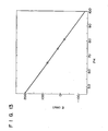
- Example 62 After an oxidation/reduction film was formed on a BPG base in a similar manner to that in Example 62, it was dipped in an dipping solution (solvent: 5 ml of tetrahydrofuran) having the composition shown in Table 12 so as to form a potassium ion carrier film. Immersion was performed 20 times, and the film was dried upon each immersion with hot air at 100°C or lower.
- Fig. 20 shows the relationship between the electromotive force (with reference to the SSCE) and the logarithmic value of the potassium ion concentration. Referring to Fig. 20, line a corresponds to the sensor of Example 62, line b corresponds to the sensor of Example 63, and line c corresponds to the sensor of Example 64.
- a sodium ion sensor having the structure as shown in Fig. 2 was prepared by the following method:
- Electrolytic Solution Acetonitrile containing 0.2 M of sodium perchlorate as a supporting electrolyte and 0.5 M of 2,6-xylenol as a reactive substance Electrolysis Conditions After the electrolysis potential was swept three times from 0 V to 1.5 V vs. SSEC (sweep rate: 50 mV/sec), constant potential electrolysis was performed at 1.5 V for 10 minutes.
- an electrooxidation polymer film of 2,6-xylenol (having a thickness of about 30 ⁇ m) was formed on the exposed surface of the BPG base.
- the polymer film was dark blue in color.
- the sensor obtained in this manner was dried well, dipped in a 1 mM sodium chloride aqueous solution for 2 hours, and tested.
- the response of the sodium ion sensor prepared in Example 65 to sodium ions was examined by dipping it in a 8 x 10 -4 to 3 x 10 -1 M sodium chloride aqueous solution together with an SSCE and measuring the electromotive force of the sensor. Measurement was performed at 37°C. The obtained results are shown in Fig. 21.
- the electromotive force had a good linear relation with the sodium ion concentration within a concentration range of 10 -4 to 10 0 M .
- time required for the sensor to reach a potential 95%-of the equilibrium potential (95% response time) was within 1 minute.
- Example 65 In order to examine the influence of dissolved oxygen on the electromotive force of the sodium ion sensor prepared in Example 65, the working electrode of Example 65 and a reference electrode (SSCE) were dipped in the same solution so as to saturate the film with the dissolved gas. A difference between the electromotive force when pure nitrogen gas (flow rate: 100 ml/min) was blown into the solution for 3 hours and that when oxygen gas (flow rate: 100 ml/min) was blown into the solution for 5 hours was measured. As a result, the difference in electromotive force was within + 2 mV. It is seen from this fact that the sensor of the present invention can measure the sodium ion concentration without being influenced by the dissolved oxygen in the measuring solution.
- SSCE reference electrode
- a disk (thickness: 5 mm; diameter: 5.0 mm) was cut from a plate of basal plane pyrolytic graphite (BPG).
- a lead wire (teflon coated copper wire) was connected to one end face of the disk with a conductive adhesive ("C-850-6" available from Amicon K.K.)
- the base was inserted into a heat shrinkable tube such that the end face of the base, not having the lead wire connected, slightly projected from the tube end face.
- the tube was allowed to shrink by heating so as to insulate the base.
- the projecting end face of the base was peeled by a thin layer so as to expose a new surface.
- Electrooxidation polymerization was performed in a three electrode electrolysis cell under the following conditions using the base structure as a working electrode, a saturated sodium chloride calomel electrode (SSCE) as a reference electrode and a platinum net as a counter electrode. An electrooxidation polymer film was thus formed on the exposed surface of the base.
- SSCE saturated sodium chloride calomel electrode
- the electrolytic solution used was obtained by adding 10 mM/l of 1-aminopyrene and 10 mM/l of pyridine to an acetonitrile solvent containing 0.2 m/l of sodium perchlorate as a supporting electrolyte. Constant potential electrolysis was performed at +1.0 V (with reference to the SSCE) after the potential of the working electrode was swept at + 1 . 0 V (with reference to the SSCE) from 0 V to + 1 . 0 V at a sweeping speed of 50 mV/sec three times.
- an electrooxidation polymer film of 1-aminopyrene (redox polymer) was formed on the exposed surface of the base.
- the resultant redox polymer film had a thickness of about 30 ⁇ m.
- a calcium ion carrier film was formed by the following method.
- a solution was prepared by dissolving in 5 ml of tetrahydrofuran, 22.5 mg of calcium bis[(n-octylphenyl) phosphate], 8.6 mg of potassium tetrakis-p-chlorophenyl borate, 493.8 mg of dioctyl sebacate, and 251.1 mg of vinyl chloride (average polymerization degree: 1,050).
- the oxidation/reduction film was dipped in the resultant solution and dried, and the process was repeated to form a calcium ion carrier film having a thickness of about 0.3 mm.
- Example 66 In order to examine the response of the calcium ion sensor prepared in Example 66 to calcium ion concentration, the sensor was dipped together with an SSCE in an aqueous solution containing 10 -3 to 10 -1 M/l of calcium chloride.
- the electromotive force of the sensor (with reference to the SSCE) was measured with an electrometer ("TR8652" available from Takeda Riken K.K.) (measurement temperature: 25°C+0.1 °C).
- TR8652 available from Takeda Riken K.K.
- the line had a slope of about 19 mV/log ⁇ [Ca 2+ ](M) ⁇ .
- a calcium ion carrier film having a thickness of about 0.4 mm similar to that in Example 66 was deposited on the resultant redox polymer film.
- the objective calcium ion sensor was thus prepared.
- Example 67 When the characteristics of the calcium ion sensor prepared in Example 67 were examined following the same procedures as in Example 45, the electromotive force of the ion sensor and the calcium ion concentration had a linear relation as shown in Fig. 23. The 95% response time was 1 to 2 minutes.
- the magnesium ion selection coefficient was measured in the presence of magnesium ions (25°C+0.1°C), and logK Pot Ca Mg was -3.33. This value is significantly smaller than the value, -1.9 to -2.0 of the conventional calcium ion sensor. It is thus demonstrated that the calcium ion sensor of the present invention is less prone to the influence of Mg ions (Fig. 24).
- the calcium ion selection coefficient in the presence of sodium ions was measured (25°C+0.1°C) using the calcium ion sensor of Example 67.
- the logK Pot Ca Na was 7. 5 x 10 -4 . This reveals that the calcium ion sensor of the present invention is less prone to the influence of sodium ions.
- the calcium ion concentration could be measured without the influence of the magnesium ions within the range of the [Mg 2+ ] between 1 0 -1 M and 10 -2 M .
- a column having a diameter of 5 mm was cut from a plate of basal plane pyrolytic graphite (BPG: available from Union Carbide Corp.) A leading wire was connected to the bottom of the column with a conductive adhesive ( " C-850-6 " available from Amicon K.K.) The structure was covered with a heat shrinkable tube such that a top surface 21a of the BPG projected slightly. The projecting end of the BPG base was peeled with a knife blade to expose a new surface. Electrooxidation polymerization was performed under the following conditions using the structure as a working electrode, a saturated sodium chloride calomel electrode (SSCE) as a reference electrode and a platinum net as a counter electrode.
- SSCE saturated sodium chloride calomel electrode
- Electrolytic Solution Acetonitrile containing 0.2 M of sodium perchlorate as a supporting electrolyte and 0.5 M of 2,6-xylenol as a reactive substance Electrolysis Conditions After sweeping the electrolysis potential three times from 0 V to 1.5 V (sweeping speed: 50 mV/sec), constant potential electrolysis at 1.5 V was performed for 10 minutes.
- the polymer film was rinsed with a methanol solution to remove nonreacted 2,6-xylenol, it was rinsed with water, dipped in 0.1 M sodium chloride solution for 1 hour, rinsed with water and dried.
- the senor was dried well, it was dipped in a 1 mM sodium chloride aqueous solution for 2 hours, and tested.
- the response of the chlorine ion sensor prepared in Example 67 was examined by measuring the electromotive force of the sensor by dipping the sensor in a 10 -4 to 10 0 M sodium chloride solution. Measurement was performed at 37°C. The obtained results are shown in Fig. 25.
- the electromotive force and the chlorine ion concentration had a linear relation within a concentration range of 10 -4 to 1 0 0 M .
- the time required for-the sensor to reach a potential 95% of the equilibrium potential (95% response time) was within 1 minute.
- the oxygen partial pressure pO 2 of the measuring solution of Test Example 48 was changed within the range of 0 to 700 mmHg and the electromotive force was measured as in Test Example 48.
- the difference in electromotive force was within + 2 mV. It was thus demonstrated that the chlorine ion sensor of the present invention can measure the chlorine ion concentration without being influenced by the dissolved oxygen in the measuring solution.
- BPG disks were prepared and an electrooxidation was performed under the conditions below to form an electrooxidation polymer film on each BPG disk.
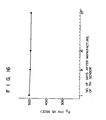
- Example 72 The sensor of Example 72 was dipped in a 10 -3 to 10 -1 M solution of sodium hydrogencarbonate together with SSCE, and the electromotive force of the sensor was determined against the concentration of the hydrogencarbonate ions. The results are shown in Fig. 28.
- the ion sensor of the present invention generates a potential corresponding to a concentration of a specific type of ions in an aqueous solution by using a carrier substance in the ion carrier film as a carrier of the specific type of ions whose concentration is to be measured.
- the sensor has a quick response and is substantially not prone to the influence of other substances which may be present in the solution (e.g., dissolved oxygen, and ions of types other than the specific type of ions). Therefore, the ion sensor of the present invention can measure the concentration of a specific type of ions in an aqueous solution quickly and with precision.
- the sensor of the present invention does not require a standard internal solution chamber and can be rendered compact in size. The sensor has excellent stability over time and allows stable ion concentration measurement over a long period of time with good reproducibility.
Landscapes
- Chemical & Material Sciences (AREA)
- Life Sciences & Earth Sciences (AREA)
- Health & Medical Sciences (AREA)
- Physics & Mathematics (AREA)
- Chemical Kinetics & Catalysis (AREA)
- Electrochemistry (AREA)
- Molecular Biology (AREA)
- Analytical Chemistry (AREA)
- Biochemistry (AREA)
- General Health & Medical Sciences (AREA)
- General Physics & Mathematics (AREA)
- Immunology (AREA)
- Pathology (AREA)
- Investigating Or Analyzing Materials By The Use Of Fluid Adsorption Or Reactions (AREA)
- Measurement Of The Respiration, Hearing Ability, Form, And Blood Characteristics Of Living Organisms (AREA)
Applications Claiming Priority (10)
| Application Number | Priority Date | Filing Date | Title |
|---|---|---|---|
| JP59281076A JPS61155949A (ja) | 1984-12-28 | 1984-12-28 | pHセンサ− |
| JP281076/84 | 1984-12-28 | ||
| JP60035691A JPS61194343A (ja) | 1985-02-25 | 1985-02-25 | Phセンサ− |
| JP35691/85 | 1985-02-25 | ||
| JP53308/85 | 1985-03-19 | ||
| JP60055177A JPS61213662A (ja) | 1985-03-19 | 1985-03-19 | pHセンサ− |
| JP60053308A JPS61213660A (ja) | 1985-03-19 | 1985-03-19 | pHセンサーの製造方法 |
| JP55177/85 | 1985-03-19 | ||
| JP60093176A JPS61251764A (ja) | 1985-04-30 | 1985-04-30 | ↓pHセンサ− |
| JP93176/85 | 1985-04-30 |
Publications (3)
| Publication Number | Publication Date |
|---|---|
| EP0186210A2 true EP0186210A2 (fr) | 1986-07-02 |
| EP0186210A3 EP0186210A3 (en) | 1987-10-07 |
| EP0186210B1 EP0186210B1 (fr) | 1992-04-22 |
Family
ID=27521720
Family Applications (1)
| Application Number | Title | Priority Date | Filing Date |
|---|---|---|---|
| EP85116605A Expired - Lifetime EP0186210B1 (fr) | 1984-12-28 | 1985-12-27 | Senseur d'ions |
Country Status (3)
| Country | Link |
|---|---|
| US (1) | US5133856A (fr) |
| EP (1) | EP0186210B1 (fr) |
| DE (1) | DE3585915T2 (fr) |
Cited By (17)
| Publication number | Priority date | Publication date | Assignee | Title |
|---|---|---|---|---|
| EP0203864A3 (en) * | 1985-05-27 | 1987-08-05 | Terumo Kabushiki Kaisha Trading As Terumo Corporation | Ion sensor and method of manufacturing same |
| EP0247941A3 (en) * | 1986-05-26 | 1989-02-22 | Terumo Kabushiki Kaisha Trading As Terumo Corporation | Gas sensor |
| EP0218530A3 (en) * | 1985-10-02 | 1989-03-15 | Terumo Kabushiki Kaisha Trading As Terumo Corporation | Ionic concentration measurement method |
| EP0245168A3 (en) * | 1986-05-01 | 1989-03-15 | Terumo Kabushiki Kaisha Trading As Terumo Corporation | Ion sensor |
| EP0228969A3 (en) * | 1985-12-25 | 1989-03-15 | Terumo Kabushiki Kaisha Trading As Terumo Corporation | Ion sensor |
| US4816118A (en) * | 1986-01-24 | 1989-03-28 | Terumo Corporation | Ion-sensitive FET sensor |
| EP0280230A3 (en) * | 1987-02-27 | 1989-05-17 | General Signal Corporation | Instrument for potentiometric electrochemical measurements in earth grounded solutions |
| WO1989004958A1 (fr) * | 1987-11-24 | 1989-06-01 | Public Health Laboratory Service Board | Electrodes electrochimiques |
| WO1990004777A1 (fr) * | 1988-10-25 | 1990-05-03 | Karl Harnoncourt | Detecteur electrochimique |
| US4968400A (en) * | 1986-11-20 | 1990-11-06 | Terumo Kabushiki Kaisha | Enzyme sensor |
| US5061976A (en) * | 1986-11-20 | 1991-10-29 | Terumo Kabushiki Kaisha | Fet electrode with carbon gate |
| NL9100184A (nl) * | 1991-02-01 | 1992-09-01 | Priva Agro Holding Bv | Werkwijze voor het maken van een membraan voor een elektrochemische of optische sensor. |
| US5156728A (en) * | 1987-02-12 | 1992-10-20 | Terumo Kabushiki Kaisha | Ion sensor |
| US5192417A (en) * | 1987-09-21 | 1993-03-09 | Terumo Kabushiki Kaisha | Lithium ion sensor |
| WO1994002629A1 (fr) * | 1992-07-28 | 1994-02-03 | The Victoria University Of Manchester | Procede et dispositif d'analyse |
| AT407199B (de) * | 1992-09-16 | 2001-01-25 | Gerald Dipl Ing Dr Urban | Ph-sensor |
| CN105738435B (zh) * | 2016-02-01 | 2018-10-23 | 中国科学院烟台海岸带研究所 | 一种氟离子的聚合物膜电位型传感器及其应用 |
Families Citing this family (94)
| Publication number | Priority date | Publication date | Assignee | Title |
|---|---|---|---|---|
| US5286364A (en) * | 1987-06-08 | 1994-02-15 | Rutgers University | Surface-modified electochemical biosensor |
| GB8927377D0 (en) * | 1989-12-04 | 1990-01-31 | Univ Edinburgh | Improvements in and relating to amperometric assays |
| US5593852A (en) | 1993-12-02 | 1997-01-14 | Heller; Adam | Subcutaneous glucose electrode |
| CA2050057A1 (fr) | 1991-03-04 | 1992-09-05 | Adam Heller | Biocapteurs d'elimination d'impuretes |
| US5573649A (en) * | 1991-03-20 | 1996-11-12 | Fujitsu Limited | Miniaturized oxygen electrode and process of producing same |
| US5281323A (en) * | 1991-03-20 | 1994-01-25 | Fujitsu Limited | Electrolyte composition for screen printing and miniaturized oxygen electrode and production process thereof |
| US5492611A (en) * | 1991-03-20 | 1996-02-20 | Fujitsu Limited | Miniaturized oxygen electrode |
| EP0600607A3 (en) * | 1992-10-28 | 1996-07-03 | Nakano Vinegar Co Ltd | Coulometric analysis method and a device therefor. |
| AU5458094A (en) * | 1992-11-05 | 1994-05-24 | Porton Diagnostics, Inc. | Membrane manufacturing method |
| US5401377A (en) * | 1993-08-06 | 1995-03-28 | Biomedix, Inc. | Ion-selective sensor with polymeric membrane having phospholipid dispersed therein |
| EP0661535A1 (fr) * | 1993-12-15 | 1995-07-05 | Hitachi, Ltd. | Capteur d'ions |
| US5685319A (en) * | 1995-12-18 | 1997-11-11 | Marett; Douglas Michael | Method and apparatus for determining the fertility status of women |
| DE69809391T2 (de) | 1997-02-06 | 2003-07-10 | Therasense, Inc. | Kleinvolumiger sensor zur in-vitro bestimmung |
| US6134461A (en) | 1998-03-04 | 2000-10-17 | E. Heller & Company | Electrochemical analyte |
| US6103033A (en) | 1998-03-04 | 2000-08-15 | Therasense, Inc. | Process for producing an electrochemical biosensor |
| US8465425B2 (en) | 1998-04-30 | 2013-06-18 | Abbott Diabetes Care Inc. | Analyte monitoring device and methods of use |
| US8346337B2 (en) | 1998-04-30 | 2013-01-01 | Abbott Diabetes Care Inc. | Analyte monitoring device and methods of use |
| US9066695B2 (en) | 1998-04-30 | 2015-06-30 | Abbott Diabetes Care Inc. | Analyte monitoring device and methods of use |
| US8974386B2 (en) | 1998-04-30 | 2015-03-10 | Abbott Diabetes Care Inc. | Analyte monitoring device and methods of use |
| US6949816B2 (en) | 2003-04-21 | 2005-09-27 | Motorola, Inc. | Semiconductor component having first surface area for electrically coupling to a semiconductor chip and second surface area for electrically coupling to a substrate, and method of manufacturing same |
| US8480580B2 (en) | 1998-04-30 | 2013-07-09 | Abbott Diabetes Care Inc. | Analyte monitoring device and methods of use |
| US8688188B2 (en) | 1998-04-30 | 2014-04-01 | Abbott Diabetes Care Inc. | Analyte monitoring device and methods of use |
| US6175752B1 (en) | 1998-04-30 | 2001-01-16 | Therasense, Inc. | Analyte monitoring device and methods of use |
| US6251260B1 (en) | 1998-08-24 | 2001-06-26 | Therasense, Inc. | Potentiometric sensors for analytic determination |
| US6591125B1 (en) | 2000-06-27 | 2003-07-08 | Therasense, Inc. | Small volume in vitro analyte sensor with diffusible or non-leachable redox mediator |
| US6338790B1 (en) | 1998-10-08 | 2002-01-15 | Therasense, Inc. | Small volume in vitro analyte sensor with diffusible or non-leachable redox mediator |
| EP2322645A1 (fr) | 1999-06-18 | 2011-05-18 | Abbott Diabetes Care Inc. | Capteur d'analyte in vivo limité en transfert de masse |
| US6616819B1 (en) | 1999-11-04 | 2003-09-09 | Therasense, Inc. | Small volume in vitro analyte sensor and methods |
| US6560471B1 (en) | 2001-01-02 | 2003-05-06 | Therasense, Inc. | Analyte monitoring device and methods of use |
| AU2002309528A1 (en) | 2001-04-02 | 2002-10-15 | Therasense, Inc. | Blood glucose tracking apparatus and methods |
| JP3721328B2 (ja) * | 2001-12-28 | 2005-11-30 | 日本電子株式会社 | イオンセンサー用感応膜の製造方法 |
| US7381184B2 (en) | 2002-11-05 | 2008-06-03 | Abbott Diabetes Care Inc. | Sensor inserter assembly |
| US8771183B2 (en) | 2004-02-17 | 2014-07-08 | Abbott Diabetes Care Inc. | Method and system for providing data communication in continuous glucose monitoring and management system |
| AU2003303597A1 (en) | 2002-12-31 | 2004-07-29 | Therasense, Inc. | Continuous glucose monitoring system and methods of use |
| US8066639B2 (en) | 2003-06-10 | 2011-11-29 | Abbott Diabetes Care Inc. | Glucose measuring device for use in personal area network |
| USD914881S1 (en) | 2003-11-05 | 2021-03-30 | Abbott Diabetes Care Inc. | Analyte sensor electronic mount |
| US8758593B2 (en) * | 2004-01-08 | 2014-06-24 | Schlumberger Technology Corporation | Electrochemical sensor |
| US9788771B2 (en) | 2006-10-23 | 2017-10-17 | Abbott Diabetes Care Inc. | Variable speed sensor insertion devices and methods of use |
| US9743862B2 (en) | 2011-03-31 | 2017-08-29 | Abbott Diabetes Care Inc. | Systems and methods for transcutaneously implanting medical devices |
| US9351669B2 (en) | 2009-09-30 | 2016-05-31 | Abbott Diabetes Care Inc. | Interconnect for on-body analyte monitoring device |
| US9572534B2 (en) | 2010-06-29 | 2017-02-21 | Abbott Diabetes Care Inc. | Devices, systems and methods for on-skin or on-body mounting of medical devices |
| US8613703B2 (en) | 2007-05-31 | 2013-12-24 | Abbott Diabetes Care Inc. | Insertion devices and methods |
| US8512243B2 (en) | 2005-09-30 | 2013-08-20 | Abbott Diabetes Care Inc. | Integrated introducer and transmitter assembly and methods of use |
| US20090105569A1 (en) | 2006-04-28 | 2009-04-23 | Abbott Diabetes Care, Inc. | Introducer Assembly and Methods of Use |
| US9259175B2 (en) | 2006-10-23 | 2016-02-16 | Abbott Diabetes Care, Inc. | Flexible patch for fluid delivery and monitoring body analytes |
| US7697967B2 (en) | 2005-12-28 | 2010-04-13 | Abbott Diabetes Care Inc. | Method and apparatus for providing analyte sensor insertion |
| US9398882B2 (en) | 2005-09-30 | 2016-07-26 | Abbott Diabetes Care Inc. | Method and apparatus for providing analyte sensor and data processing device |
| US10226207B2 (en) | 2004-12-29 | 2019-03-12 | Abbott Diabetes Care Inc. | Sensor inserter having introducer |
| US8571624B2 (en) | 2004-12-29 | 2013-10-29 | Abbott Diabetes Care Inc. | Method and apparatus for mounting a data transmission device in a communication system |
| US7731657B2 (en) | 2005-08-30 | 2010-06-08 | Abbott Diabetes Care Inc. | Analyte sensor introducer and methods of use |
| US8333714B2 (en) | 2006-09-10 | 2012-12-18 | Abbott Diabetes Care Inc. | Method and system for providing an integrated analyte sensor insertion device and data processing unit |
| US7883464B2 (en) | 2005-09-30 | 2011-02-08 | Abbott Diabetes Care Inc. | Integrated transmitter unit and sensor introducer mechanism and methods of use |
| US8112240B2 (en) | 2005-04-29 | 2012-02-07 | Abbott Diabetes Care Inc. | Method and apparatus for providing leak detection in data monitoring and management systems |
| US9521968B2 (en) | 2005-09-30 | 2016-12-20 | Abbott Diabetes Care Inc. | Analyte sensor retention mechanism and methods of use |
| US7766829B2 (en) | 2005-11-04 | 2010-08-03 | Abbott Diabetes Care Inc. | Method and system for providing basal profile modification in analyte monitoring and management systems |
| US11298058B2 (en) | 2005-12-28 | 2022-04-12 | Abbott Diabetes Care Inc. | Method and apparatus for providing analyte sensor insertion |
| EP1968432A4 (fr) | 2005-12-28 | 2009-10-21 | Abbott Diabetes Care Inc | Insertion d'un dispositif medical |
| US7885698B2 (en) | 2006-02-28 | 2011-02-08 | Abbott Diabetes Care Inc. | Method and system for providing continuous calibration of implantable analyte sensors |
| US7620438B2 (en) | 2006-03-31 | 2009-11-17 | Abbott Diabetes Care Inc. | Method and system for powering an electronic device |
| US8226891B2 (en) | 2006-03-31 | 2012-07-24 | Abbott Diabetes Care Inc. | Analyte monitoring devices and methods therefor |
| WO2007143225A2 (fr) | 2006-06-07 | 2007-12-13 | Abbott Diabetes Care, Inc. | Système et procédé de surveillance d'un analyte |
| US8732188B2 (en) | 2007-02-18 | 2014-05-20 | Abbott Diabetes Care Inc. | Method and system for providing contextual based medication dosage determination |
| US8930203B2 (en) | 2007-02-18 | 2015-01-06 | Abbott Diabetes Care Inc. | Multi-function analyte test device and methods therefor |
| US8123686B2 (en) | 2007-03-01 | 2012-02-28 | Abbott Diabetes Care Inc. | Method and apparatus for providing rolling data in communication systems |
| US7928850B2 (en) | 2007-05-08 | 2011-04-19 | Abbott Diabetes Care Inc. | Analyte monitoring system and methods |
| US8456301B2 (en) | 2007-05-08 | 2013-06-04 | Abbott Diabetes Care Inc. | Analyte monitoring system and methods |
| US8665091B2 (en) | 2007-05-08 | 2014-03-04 | Abbott Diabetes Care Inc. | Method and device for determining elapsed sensor life |
| US8461985B2 (en) | 2007-05-08 | 2013-06-11 | Abbott Diabetes Care Inc. | Analyte monitoring system and methods |
| US8103456B2 (en) | 2009-01-29 | 2012-01-24 | Abbott Diabetes Care Inc. | Method and device for early signal attenuation detection using blood glucose measurements |
| US9402544B2 (en) | 2009-02-03 | 2016-08-02 | Abbott Diabetes Care Inc. | Analyte sensor and apparatus for insertion of the sensor |
| US20100213057A1 (en) | 2009-02-26 | 2010-08-26 | Benjamin Feldman | Self-Powered Analyte Sensor |
| FR2943421B1 (fr) * | 2009-03-18 | 2012-11-30 | Commissariat Energie Atomique | Detection et quantification electrique de derives mercuriques |
| WO2010127050A1 (fr) | 2009-04-28 | 2010-11-04 | Abbott Diabetes Care Inc. | Détection d'erreur dans des données de répétition critiques dans un système de capteur sans fil |
| WO2010138856A1 (fr) | 2009-05-29 | 2010-12-02 | Abbott Diabetes Care Inc. | Systèmes d'antenne de dispositif médical comportant des configurations d'antenne externe |
| EP2473099A4 (fr) | 2009-08-31 | 2015-01-14 | Abbott Diabetes Care Inc | Système de surveillance de substance à analyser et procédés de gestion de l'énergie et du bruit |
| WO2011026147A1 (fr) | 2009-08-31 | 2011-03-03 | Abbott Diabetes Care Inc. | Dispositif et procédés de traitement de signal d'analyte |
| US9320461B2 (en) | 2009-09-29 | 2016-04-26 | Abbott Diabetes Care Inc. | Method and apparatus for providing notification function in analyte monitoring systems |
| USD924406S1 (en) | 2010-02-01 | 2021-07-06 | Abbott Diabetes Care Inc. | Analyte sensor inserter |
| ES2881798T3 (es) | 2010-03-24 | 2021-11-30 | Abbott Diabetes Care Inc | Insertadores de dispositivos médicos y procedimientos de inserción y uso de dispositivos médicos |
| US11064921B2 (en) | 2010-06-29 | 2021-07-20 | Abbott Diabetes Care Inc. | Devices, systems and methods for on-skin or on-body mounting of medical devices |
| GB2490117B (en) | 2011-04-18 | 2014-04-09 | Schlumberger Holdings | Electrochemical pH sensor |
| WO2012083258A2 (fr) * | 2010-12-16 | 2012-06-21 | Sensor Innovations, Inc. | Capteurs électrochimiques |
| DE102012105283A1 (de) * | 2011-06-24 | 2012-12-27 | Endress + Hauser Conducta Gesellschaft für Mess- und Regeltechnik mbH + Co. KG | Messaufnehmer zur Bestimmung einer einen Gehalt von H+- und/oder OH--Ionen in einem Messmedium repräsentierenden Messgröße |
| CA2840640C (fr) | 2011-11-07 | 2020-03-24 | Abbott Diabetes Care Inc. | Dispositif et procedes de controle de substance a analyser |
| AU2012352560B2 (en) | 2011-12-11 | 2017-01-19 | Abbott Diabetes Care Inc. | Analyte sensor devices, connections, and methods |
| US9968306B2 (en) | 2012-09-17 | 2018-05-15 | Abbott Diabetes Care Inc. | Methods and apparatuses for providing adverse condition notification with enhanced wireless communication range in analyte monitoring systems |
| CA2984939A1 (fr) | 2015-05-14 | 2016-11-17 | Abbott Diabetes Care Inc. | Instruments d'introduction de dispositifs medicaux compacts et systemes et procedes associes |
| US10213139B2 (en) | 2015-05-14 | 2019-02-26 | Abbott Diabetes Care Inc. | Systems, devices, and methods for assembling an applicator and sensor control device |
| US11071478B2 (en) | 2017-01-23 | 2021-07-27 | Abbott Diabetes Care Inc. | Systems, devices and methods for analyte sensor insertion |
| MX2021007294A (es) | 2018-12-21 | 2021-07-15 | Abbott Diabetes Care Inc | Sistemas, dispositivos y metodos para la insercion de sensores de analito. |
| EP4203819B1 (fr) | 2020-08-31 | 2024-07-31 | Abbott Diabetes Care Inc. | Systèmes, dispositifs et procédés d'insertion de capteur d'analyte |
| ES3000715T3 (en) | 2020-09-15 | 2025-03-03 | Abbott Diabetes Care Inc | Device for analyte monitoring |
| JP2024527596A (ja) | 2021-07-16 | 2024-07-25 | アボット ダイアベティス ケア インコーポレイテッド | 検体監視のためのシステム、装置、及び方法 |
| CN115980149B (zh) * | 2022-11-30 | 2026-03-27 | 富泰华工业(深圳)有限公司 | 化学测试探头电解液、制备方法及自动补加电解液装置 |
Family Cites Families (14)
| Publication number | Priority date | Publication date | Assignee | Title |
|---|---|---|---|---|
| US3598713A (en) * | 1969-06-03 | 1971-08-10 | Corning Glass Works | Potassium ion sensitive electrode |
| GB1437091A (en) * | 1972-10-02 | 1976-05-26 | Radiometer As | Calcium electrode and membrane and composition for use therein |
| US3957612A (en) * | 1974-07-24 | 1976-05-18 | General Electric Company | In vivo specific ion sensor |
| US4115209A (en) * | 1974-10-30 | 1978-09-19 | Research Corporation | Method of determining ion activity using coated ion selective electrodes |
| US4214968A (en) * | 1978-04-05 | 1980-07-29 | Eastman Kodak Company | Ion-selective electrode |
| EP0056283B1 (fr) * | 1981-01-14 | 1985-07-31 | Terumo Corporation | Détecteur d'ions |
| US4563263A (en) * | 1982-01-15 | 1986-01-07 | Terumo Corporation | Selectively permeable film and ion sensor |
| IT1151365B (it) * | 1982-03-26 | 1986-12-17 | Oronzio De Nora Impianti | Anodo per procedimenti elettrilitici |
| US4510034A (en) * | 1982-08-31 | 1985-04-09 | Asahi Kasei Kogyo Kabushiki Kaisha | Coating type insoluble lead dioxide anode |
| US4454007A (en) * | 1983-01-27 | 1984-06-12 | E. I. Du Pont De Nemours And Company | Ion-selective layered sensor and methods of making and using the same |
| JPS6053842A (ja) * | 1983-09-05 | 1985-03-27 | Hitachi Ltd | 流通式電解セル |
| US4566949A (en) * | 1983-10-19 | 1986-01-28 | Hewlett-Packard Company | Method of operating a self cleaning electrochemical detector |
| US4541905A (en) * | 1983-12-13 | 1985-09-17 | The Ohio State University Research Foundation | Electrodes for use in electrocatalytic processes |
| US4549951A (en) * | 1984-09-11 | 1985-10-29 | Sentech Medical Corporation | Ion selective electrode |
-
1985
- 1985-12-27 DE DE8585116605T patent/DE3585915T2/de not_active Expired - Fee Related
- 1985-12-27 EP EP85116605A patent/EP0186210B1/fr not_active Expired - Lifetime
-
1990
- 1990-09-04 US US07/577,050 patent/US5133856A/en not_active Expired - Fee Related
Cited By (21)
| Publication number | Priority date | Publication date | Assignee | Title |
|---|---|---|---|---|
| EP0203864A3 (en) * | 1985-05-27 | 1987-08-05 | Terumo Kabushiki Kaisha Trading As Terumo Corporation | Ion sensor and method of manufacturing same |
| EP0218530A3 (en) * | 1985-10-02 | 1989-03-15 | Terumo Kabushiki Kaisha Trading As Terumo Corporation | Ionic concentration measurement method |
| EP0228969A3 (en) * | 1985-12-25 | 1989-03-15 | Terumo Kabushiki Kaisha Trading As Terumo Corporation | Ion sensor |
| US4816118A (en) * | 1986-01-24 | 1989-03-28 | Terumo Corporation | Ion-sensitive FET sensor |
| US4871442A (en) * | 1986-05-01 | 1989-10-03 | Terumo Corporation | Ion sensor |
| EP0245168A3 (en) * | 1986-05-01 | 1989-03-15 | Terumo Kabushiki Kaisha Trading As Terumo Corporation | Ion sensor |
| EP0247941A3 (en) * | 1986-05-26 | 1989-02-22 | Terumo Kabushiki Kaisha Trading As Terumo Corporation | Gas sensor |
| US4968400A (en) * | 1986-11-20 | 1990-11-06 | Terumo Kabushiki Kaisha | Enzyme sensor |
| US5061976A (en) * | 1986-11-20 | 1991-10-29 | Terumo Kabushiki Kaisha | Fet electrode with carbon gate |
| US5156728A (en) * | 1987-02-12 | 1992-10-20 | Terumo Kabushiki Kaisha | Ion sensor |
| EP0280230A3 (en) * | 1987-02-27 | 1989-05-17 | General Signal Corporation | Instrument for potentiometric electrochemical measurements in earth grounded solutions |
| US5192417A (en) * | 1987-09-21 | 1993-03-09 | Terumo Kabushiki Kaisha | Lithium ion sensor |
| AU613135B2 (en) * | 1987-11-24 | 1991-07-25 | Public Health Laboratory Service Board | Electrochemical electrodes |
| US4995960A (en) * | 1987-11-24 | 1991-02-26 | Public Health Laboratory Service Board | Electrochemical electrodes |
| WO1989004958A1 (fr) * | 1987-11-24 | 1989-06-01 | Public Health Laboratory Service Board | Electrodes electrochimiques |
| AT392848B (de) * | 1988-10-25 | 1991-06-25 | Karl Dr Harnoncourt | Elektrochemischer sensor |
| WO1990004777A1 (fr) * | 1988-10-25 | 1990-05-03 | Karl Harnoncourt | Detecteur electrochimique |
| NL9100184A (nl) * | 1991-02-01 | 1992-09-01 | Priva Agro Holding Bv | Werkwijze voor het maken van een membraan voor een elektrochemische of optische sensor. |
| WO1994002629A1 (fr) * | 1992-07-28 | 1994-02-03 | The Victoria University Of Manchester | Procede et dispositif d'analyse |
| AT407199B (de) * | 1992-09-16 | 2001-01-25 | Gerald Dipl Ing Dr Urban | Ph-sensor |
| CN105738435B (zh) * | 2016-02-01 | 2018-10-23 | 中国科学院烟台海岸带研究所 | 一种氟离子的聚合物膜电位型传感器及其应用 |
Also Published As
| Publication number | Publication date |
|---|---|
| EP0186210A3 (en) | 1987-10-07 |
| DE3585915D1 (de) | 1992-10-15 |
| DE3585915T2 (de) | 1993-04-15 |
| US5133856A (en) | 1992-07-28 |
| EP0186210B1 (fr) | 1992-04-22 |
Similar Documents
| Publication | Publication Date | Title |
|---|---|---|
| EP0186210B1 (fr) | Senseur d'ions | |
| EP0228969B1 (fr) | Détecteur d'ions | |
| EP0247941B1 (fr) | Capteur de gaz | |
| US4871442A (en) | Ion sensor | |
| US4925544A (en) | Electrochemical sensor with solid phase electrolyte | |
| LeBlanc et al. | Long-lived potassium ion selective polymer membrane electrode | |
| US5139626A (en) | Ion concentration measurement method | |
| EP0218530B1 (fr) | Méthode de mesure d'une concentration ionique | |
| JPS61251764A (ja) | ↓pHセンサ− | |
| EP0316380B1 (fr) | Detecteur electrochimique avec electrolyte a phase solide | |
| EP0411127A1 (fr) | Couche mince sensible aux ions, son procede de production, et capteur d'ions | |
| JPS61194343A (ja) | Phセンサ− | |
| JPH0376863B2 (fr) | ||
| JPS61213662A (ja) | pHセンサ− | |
| JPH049471B2 (fr) | ||
| JPH0375064B2 (fr) | ||
| JPH052188B2 (fr) | ||
| JPH0641929B2 (ja) | イオンセンサ− | |
| JPS61213661A (ja) | pHセンサ− | |
| JPH0422465B2 (fr) | ||
| JPH0376862B2 (fr) | ||
| JPS62150150A (ja) | Phセンサ− | |
| JPH0362225B2 (fr) | ||
| JPH0362226B2 (fr) | ||
| HU208742B (en) | Method for ion-selective amperometric measuring concentration |
Legal Events
| Date | Code | Title | Description |
|---|---|---|---|
| PUAI | Public reference made under article 153(3) epc to a published international application that has entered the european phase |
Free format text: ORIGINAL CODE: 0009012 |
|
| 17P | Request for examination filed |
Effective date: 19860124 |
|
| AK | Designated contracting states |
Kind code of ref document: A2 Designated state(s): CH DE FR GB LI NL SE |
|
| PUAL | Search report despatched |
Free format text: ORIGINAL CODE: 0009013 |
|
| AK | Designated contracting states |
Kind code of ref document: A3 Designated state(s): CH DE FR GB LI NL SE |
|
| 17Q | First examination report despatched |
Effective date: 19890602 |
|
| GRAA | (expected) grant |
Free format text: ORIGINAL CODE: 0009210 |
|
| PUAB | Information related to the publication of an a document modified or deleted |
Free format text: ORIGINAL CODE: 0009199EPPU |
|
| PUAC | Information related to the publication of a b1 document modified or deleted |
Free format text: ORIGINAL CODE: 0009299EPPU |
|
| AK | Designated contracting states |
Kind code of ref document: B1 Designated state(s): CH DE FR GB LI NL SE |
|
| DB1 | Publication of patent cancelled | ||
| RA1 | Application published (corrected) |
Date of ref document: 19860702 Kind code of ref document: A2 |
|
| NLXE | Nl: other communications concerning ep-patents (part 3 heading xe) |
Free format text: IN PAT.BUL.11/92,SHOULD BE DELETED |
|
| GRAA | (expected) grant |
Free format text: ORIGINAL CODE: 0009210 |
|
| AK | Designated contracting states |
Kind code of ref document: B1 Designated state(s): CH DE FR GB LI NL SE |
|
| PG25 | Lapsed in a contracting state [announced via postgrant information from national office to epo] |
Ref country code: LI Effective date: 19920909 Ref country code: CH Effective date: 19920909 |
|
| ET | Fr: translation filed | ||
| REF | Corresponds to: |
Ref document number: 3585915 Country of ref document: DE Date of ref document: 19921015 |
|
| REG | Reference to a national code |
Ref country code: CH Ref legal event code: PL |
|
| NLV1 | Nl: lapsed or annulled due to failure to fulfill the requirements of art. 29p and 29m of the patents act | ||
| PLBE | No opposition filed within time limit |
Free format text: ORIGINAL CODE: 0009261 |
|
| STAA | Information on the status of an ep patent application or granted ep patent |
Free format text: STATUS: NO OPPOSITION FILED WITHIN TIME LIMIT |
|
| 26N | No opposition filed | ||
| NLXE | Nl: other communications concerning ep-patents (part 3 heading xe) |
Free format text: PAT.BUL.04/93 SHOULD DE DELETED |
|
| EAL | Se: european patent in force in sweden |
Ref document number: 85116605.8 |
|
| PGFP | Annual fee paid to national office [announced via postgrant information from national office to epo] |
Ref country code: SE Payment date: 20011206 Year of fee payment: 17 |
|
| PGFP | Annual fee paid to national office [announced via postgrant information from national office to epo] |
Ref country code: FR Payment date: 20011212 Year of fee payment: 17 |
|
| PGFP | Annual fee paid to national office [announced via postgrant information from national office to epo] |
Ref country code: GB Payment date: 20011227 Year of fee payment: 17 |
|
| REG | Reference to a national code |
Ref country code: GB Ref legal event code: IF02 |
|
| PGFP | Annual fee paid to national office [announced via postgrant information from national office to epo] |
Ref country code: DE Payment date: 20020109 Year of fee payment: 17 |
|
| PG25 | Lapsed in a contracting state [announced via postgrant information from national office to epo] |
Ref country code: GB Free format text: LAPSE BECAUSE OF NON-PAYMENT OF DUE FEES Effective date: 20021227 |
|
| PG25 | Lapsed in a contracting state [announced via postgrant information from national office to epo] |
Ref country code: SE Free format text: LAPSE BECAUSE OF NON-PAYMENT OF DUE FEES Effective date: 20021228 |
|
| PGFP | Annual fee paid to national office [announced via postgrant information from national office to epo] |
Ref country code: NL Payment date: 20021231 Year of fee payment: 18 |
|
| PG25 | Lapsed in a contracting state [announced via postgrant information from national office to epo] |
Ref country code: DE Free format text: LAPSE BECAUSE OF NON-PAYMENT OF DUE FEES Effective date: 20030701 |
|
| EUG | Se: european patent has lapsed | ||
| GBPC | Gb: european patent ceased through non-payment of renewal fee |
Effective date: 20021227 |
|
| PG25 | Lapsed in a contracting state [announced via postgrant information from national office to epo] |
Ref country code: FR Free format text: LAPSE BECAUSE OF NON-PAYMENT OF DUE FEES Effective date: 20030901 |
|
| REG | Reference to a national code |
Ref country code: FR Ref legal event code: ST |
|
| PG25 | Lapsed in a contracting state [announced via postgrant information from national office to epo] |
Ref country code: NL Free format text: LAPSE BECAUSE OF NON-PAYMENT OF DUE FEES Effective date: 20040701 |
|
| NLV4 | Nl: lapsed or anulled due to non-payment of the annual fee |
Effective date: 20040701 |