EP0186488A2 - Ferngesteuerte bewegbare Vorrichtung zur Inspektion von Gebieten mit beschränkter Zugänglichkeit - Google Patents
Ferngesteuerte bewegbare Vorrichtung zur Inspektion von Gebieten mit beschränkter Zugänglichkeit Download PDFInfo
- Publication number
- EP0186488A2 EP0186488A2 EP85309405A EP85309405A EP0186488A2 EP 0186488 A2 EP0186488 A2 EP 0186488A2 EP 85309405 A EP85309405 A EP 85309405A EP 85309405 A EP85309405 A EP 85309405A EP 0186488 A2 EP0186488 A2 EP 0186488A2
- Authority
- EP
- European Patent Office
- Prior art keywords
- vehicle
- drive
- magnets
- drive frame
- legs
- Prior art date
- Legal status (The legal status is an assumption and is not a legal conclusion. Google has not performed a legal analysis and makes no representation as to the accuracy of the status listed.)
- Withdrawn
Links
Images


Classifications
-
- B—PERFORMING OPERATIONS; TRANSPORTING
- B62—LAND VEHICLES FOR TRAVELLING OTHERWISE THAN ON RAILS
- B62D—MOTOR VEHICLES; TRAILERS
- B62D57/00—Vehicles characterised by having other propulsion or other ground- engaging means than wheels or endless track, alone or in addition to wheels or endless track
- B62D57/02—Vehicles characterised by having other propulsion or other ground- engaging means than wheels or endless track, alone or in addition to wheels or endless track with ground-engaging propulsion means, e.g. walking members
-
- F—MECHANICAL ENGINEERING; LIGHTING; HEATING; WEAPONS; BLASTING
- F22—STEAM GENERATION
- F22B—METHODS OF STEAM GENERATION; STEAM BOILERS
- F22B37/00—Component parts or details of steam boilers
- F22B37/002—Component parts or details of steam boilers specially adapted for nuclear steam generators, e.g. maintenance, repairing or inspecting equipment not otherwise provided for
- F22B37/006—Walking equipment, e.g. walking platforms suspended at the tube sheet
Definitions
- This invention relates to remotely controllable vehicles in the form of carts adapted to service and/or inspect areas having limited access, such as the interior of a nuclear steam generator.
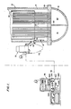
- a nuclear steam generator 12 of the type found in the prior art is shown in Figure 1 of..the attached drawings, as comprising a bundle of a large number of vertically orientated U-shaped tubes 28.
- the tubes 28 are disposed in a lower, cylindrically shaped shell 14 of the steam generator 12, the bottom end of which is associated with a radiation confining housing or channel head 16, typically of a hemi-spherical configuration as shown in Figure 1.
- the channel head 16 is divided by a partition 22 into a first half typically known as a hot leg 18, and a second half typically known as a cold leg 20.
- High-temperature primary water from a nuclear reactor is introduced into the steam generator 12, through a primary inlet (not shown) into the hot leg 18.
- the primary water passes from the hot leg into the exposed openings of the plurality of U-shaped tubes 28, flows through the tubes 28 to be introduced into the cold leg 20 and, finally, exits from the steam generator 12 through a primary outlet (not shown).
- Opposite ends of the U-shaped tubes 28 are mounted within a tube sheet 26 in communication with the hot leg 18 and the cold leg 20, respectively.
- a wrapper 24 surrounds the bundle of U-shaped tubes 28.
- Inlet or secondary water is introduced into the lower shell 14 to circulate about the U-shaped tubes 28, whereby pressurized steam is produced and supplied to a steam turbine (not shown).
- the primary water circulating through the hot let 18 and cold leg 20 of the channel head 16 is radioactive and has therein chemical contaminants.
- the high temperature water/steam environment within the steam generator 12 corrodes the U-shaped tubes 28 causing the rupture and the leakage of the radioactive primary water into the lower shell 14 of the nuclear steam generator 12.
- degradation and rupture of the U-shaped tubes 28 was attributed to either microscopic attack from chemical contaminants in the primary water or mechanical deformation.
- U.S. Patent No. 4,287,655 of Gerkey et al. discloses a machine for servicing the tube sheet 26 of the nuclear steam generator 12.
- the Gerkey et al. machine includes an arm pivoted to move in a plane parallel to and underneath the semicircular hole array in one-half of the tube sheet.
- a carriage mounted for reciprocal movement along the arm is provided with a platform which can be raised toward the tube sheet.
- various end effectors may be mounted on the platform. Due to the constraints imposed by the shape of the channel head, it is necessary that the end effectors be mounted on cantilevered arms and that the cantilevered arms be mounted at different angles on the platform in order to reach all of the holes in the array with the different end effectors. In some instances, cantilevered arms of more than one length are required for one type of end effectors in order that the desired operations can be performed at each of the holes in the array.
- the alignment of the end effectors causes sensor elements associated with the cantilevered arms to generate signals indicative of the position of the aligned tube holes in the channel head 16, whereby various servicing operations, e.g., drilling, may be carried out upon that tube within the aligned hole.
- U.S. Patent No. 3,811,320 of Cowell describes apparatus controllably moved through such limited access areas as a tank or the like.
- the Cowell apparatus includes a vertically disposed cross-member having a track to be reciprocally driven by a motor, and a horizontally disposed cross-member likewise having a track reciprocally driven by a second motor.
- Each of the first and second cross-members have a pair of electromagnets for releasably attaching its cross-members to the wall of the tank.
- Each cross-member rides on the track of the other cross-member, so that as one cross-member is attached by its pair of electromagnets to the wall, the other cross-member is driven by its motor to the next position.
- Movement is achieved by first energizing the magnets of the vertically disposed cross-member and, then, driving the horizontally disposed cross-member in a horizontal direction. Thereafter, the pair of magnets of the horizontally disposed cross-member is energized and those of the vertically disposed cross-member de-energized, whereby the vertically disposed member may be moved to a different position.
- the apparatus may be moved in a vertical direction by reciprocally energizing the first motor and selectively energizing and de-energizing the magnets on the first and second cross-members.
- both of these motors are energized while one cross beam member is locked in position by its pair of electromagnets, then the apparatus may be driven in a 45° direction with respect to its cross-members. Movement of this device is stated to be controlled by computer, but the details of such control are not disclosed. Further, no means are disclosed, whereby the exact position of the servicing or sensing apparatus is ascertained.
- the invention in its broad form comprises an unmanned remotely controllable inspection vehicle for controlled crawling movement along a surface, said vehicle comprising:' a) a drive frame comprised of first and second opposing legs, and third and fourth opposing legs pivotably connected to said first and second legs to form said drive frame; b) drive means for selectively spreading open and collapsively closing said drive frame; characterized by c) first and second attachment means mounted on said drive frame and being actuable to become attached to said surface and being deactuable to be released from said surface; and d) control means responsive to the opening and closing of said drive frame for alternately actuating and deactuating said first and second attachment means, whereby said vehicle can be driven across the surface without falling off the surface.
- a vehicle which is controllably moved along a surface as may, illustratively, be required for inspecting or servicing a remote, limited access location.
- the vehicle has a drive frame comprised of first and second opposing legs, and third and fourth opposing legs pivotably connected to the first and second legs to form a parallelogram.
- a drive mechanism is interconnected between the first and second legs of the parallelogram drive frame for opening and closing the drive frame.
- First and second attachment devices illustratively in the form of magnets, are also attached to the first and second legs.
- a vehicle control system taking the form of a programmable computer in an illustrative embodiment of this invention responds to the opening and closing of the drive frame for alternatively actuating and deactuating the first and second attachment devices, whereby the vehicle is driven along the surface.
- the vehicle control system actuates the first attachment device and deactuates the second attachment device upon the closing of the drive frame to move the vehicle in a first direction, while actuating the second attachment device and deactuating the first attachment device upon the opening of the drive frame to move the vehicle in a second, different direction.
- the drive mechanism comprises an electrically energizable motor mounted on the first leg for rotatably driving an eccentric.
- a drive arm is driven by the eccentric and its driven end is coupled to the second opposing leg, whereby the drive frame is opened and closed.
- An indicating disk with openings therein is attached to the eccentric and an optical switch means senses the openings to provide a train of signals.
- the vehicle control system senses the train of signals to determine the relative position of the drive arm and the drive frame and to selectively actuate the. attachment devices to 'dr'ive'.the vehicle across the surface.
- the drive frame includes a pair of magnets disposed on each of the opposing first and second legs
- the vehicle control system includes a tilt sensor that provides a first signal indicative of a counterclockwise tilt with respect to vertical and a second signal indicative of a clockwise tilt.
- the vehicle control system is responsive to the first and second tilt indicating signals to de-energize one of the pair of magnets disposed on the trailing leg, considering the direction of vehicle movement, dependent on the direction of the tilt, i.e., clockwise or counterclockwise.
- an electromagnetic crawler 10 in accordance with the teachings of this invention and the manner in which it is disposed upon the inner, peripheral surface of the shell 14 of the nuclear steam generator 12.
- the electromagnetic crawler 10 is designed to be controllably directed about the shell 14, whereby data concerning the condition of the U-shaped tubes 28 may be gathered and stored at a remotely disposed control and recording station 36.
- the control and recording station 36 is coupled by an interconnecting bus 38 with a hand hole station 32 that is disposed at the hand hole 30 of the nuclear steam generator 12.
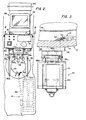
- the hand hole station 32 is coupled by a fiber conduit 34 and a power/logic cable 44, as shown in Figure 2, to the electromagnetic crawler 10.
- a computer implemented control system is employed within the control and recording station 36 to actuate the electromagnetic crawler 10 in a sequence of controlled incremental movements about the inner periphery of the shell 14.
- a command in terms of a count is entered into this computer, whereby the electromagnetic crawler 10 may be directed to a defined location with respect to the hand hole 30.
- each unit of the count corresponds to an incremental movement of the electromagnetic crawler 10.
- a tubular passageway leads from the hand hole 30 through an opening with the lower shell 14 to communicate with an opening 42 within the wrapper 24.
- Such a tubular passage if present, is removed before an operator opens the hand hole cover (not shown) and inserts manually the electromagnetic crawler 10, whereby it may be secured to the inner peripheral surface of the shell 14, as will be explained.
- the hand hole 30 has an annularly shaped raised, fixture 46, upon which is mounted a support bracket 48 as particularly illustrated in Figures 2 and 4.
- the support bracket 48 includes a pair of arms 50a and 50b spaced to be disposed about the hand hole 30, and a pair of quick release bolts 54a and 54b disposable through openings 51a and 51b of the support bracket 48, thereby retaining the bracket 48 upon the raised fixture 46.
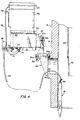
- the threaded ends of the bolts 54 are screwed into threaded inserts 56a and 56b, as disposed within the raised fixture 46, as best seen in Figure 4.
- a lamp assembly 52 is mounted upon the support bracket 48 to provide illumination of the hand hole 30 to permit insertion of the electromagnetic crawler 10 into the nuclear steam generator 12.
- the support bracket 48 is adapted to releasably receive a mounting assembly 60 comprised of a bracket 62.
- the bracket 62 is attached to the support bracket 48 by two quick release pins 58a and 58b. By removing one of the pins 58, the mounting assembly 60 may be pivoted away from the hand hole 30 to permit installation of the electromagnetic crawler 10.
- the mounting assembly 60 is fixably attached to an enclosure 64 in which is mounted an intercom 61 for communicating with the remote control and recording station 36, a DC power supply for a TV camera 68 and a DC power source for the lamp assembly 52.
- the TV camera 68 is optically coupled to the fiberscope 34, which has a manual focus control and four-way articulation of its distal tip as mounted upon the electromagnetic crawler 10. In this fashion, the distal tip may be orientated by the operator to view the selected U-shaped tubes 28 and the received image focused upon the TV camera 68.
- a CRT monitor 66 is mounted by a support frame 70 upon the enclosure 64.
- a fiberscope light supply 80 is mounted upon the CRT monitor 66.
- the fiberscope light supply 80 directs high intensity light via a fiberglass conduit 35 to the fiberscope 34. Approximately one-half of the fiberglass tubes of the fiberscope 34 transmits the high intensity light to its distal tip to thereby illuminate the interior of the nuclear steam generator 12.
- the other half of the fiberglass tubes transmits the image focused onto the distal tip of the fiberscope 34 to the TV camera 68.
- the CRT monitor 66 permits the operator to manually focus and position the distal tip of the fiberscope 34.
- the fiberscope 34 is attached to a saddle clamp 78, pivotably disposed about a pivotal shaft 76 and biased by a spring 74 to the position shown in Figure 4.
- the TV camera 68 is secured by a bolt assembly 72 to the saddle clamp 78.
- the saddle clamp 78 may rotate counterclockwise as seen in Figure 4 to permit the TV camera 68 to be repositioned away from the front of the enclosure 64 to facilitate installation of.the electromagnetic crawler 10 and to give access to the front of the enclosure 64.
- the electromagnetic crawler 10 is configured and dimensioned to fit through the hand hole 30 of the nuclear steam generator 12; the hand hole 3.0 illustratively has a 6 inch diameter.
- the electromagnetic crawler 10 is adapted to carry the distal tip of the fiberscope 34 so that it may be selectively positioned about the inner periphery of the shell 14 to view the U-shaped tubes 28.
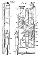
- the electromagnetic crawler 10 includes a cover 100, broken away in Figure 6 to show a parallelogram drive frame 102.
- the parallelogram drive frame 102 comprises a right channel 114 and a left channel 116, which are disposed parallel of each other and are interconnected by a pair of upper links 119a and 119b, and a pair of lower links 121a and 121b.
- the upper links 119a and 119b are connected by a screw 118a at their upper portions as shown in Figure 6 to an upper portion of the channel 114 to permit rotation of the upper links 119a and 119b with respect to the channel 114.
- the upper links 119a and 119b are connected at their lower ends by a screw 118b to the channel 116 in a manner to permit pivoting of the links 119a and 119b with respect to the channel 116.
- the lower links 121a and 121b are pivotably connected at their upper end by a screw 120a to the channel 114 and by a screw 120b to a lower portion of the channel 116.
- the eccentric drive assembly 108 functions to separate the channels 114 and 116 in cyclical fashion, whereby the electromagnetic crawler 10 may move about the inner periphery of the shell 14.
- Figure 6 illustrates the channel members 114 and 116 in their closed position;
- Figure 9 shows the channels 114 and 116 in their closed position in full line, and the channels 116 and 114 in their open position in dotted line.
- the eccentric drive assembly 108 effects the opening and closing of the channel members 114 and 116, while the upper and lower links 119 and 121 permit the desired pivoting.
- the eccentric drive assembly 108 includes a motor 150 for rotatably driving an eccentric member 160, for driving repetitively a drive arm 164 in a rectilinear fashion to open and close the channels 114 and 116 of the parallelogram drive frame 102.
- the eccentric drive motor 150 is mounted upon the channel 116 and rotatably drives the drive arm 164 whose distal tip is coupled by a coupling pin 192 to the channel 114.
- an upper left magnet 104a and a lower left magnet 106a are fixedly mounted upon the channel 114 of the electromagnetic crawler 10
- an upper right magnetic 104b and a lower right magnetic 106b are fixedly mounted upon the channel 116.
- Movement of the electromagnetic crawler 10 in a horizontal direction, as shown in Figure 6, is accomplished by energizing and de-energizing alternatively the pairs of electromagnets mounted on the channel 114 and 116 of the parallelogram drive frame 102.
- the channels 114 and 116 of the parallelogram drive frame 102 are opened and closed by the eccentric drive motor 150.
- Power and logic control for the energization and de-energization of the electromagnets 104 and 106, as well as the eccentric drive motor 150, is provided by the control and recording station 36 as applied through the power/logic cable 44 to the electromagnetic crawler 10.
- the electromagnetic crawler 10 includes an azimuth position sensor 110 comprised generally of a roller hub 250 biased by a spring 258 against the inner periphery of the shell 14 to rotate as the crawler 10 moves therealong, whereby a gauge wheel 252 is rotated past an optical switch 266, which outputs a series of electrical signals each indicative of a unit of crawler movement.
- a tilt sensor 112 is mounted by a bracket 224 upon the channel 114 to provide a signal from one of a pair of optical switches 218a and 218b depending upon whether the electromagnetic crawler 10 has tilted clockwise or counterclockwise, as seen in Figure 6.
- the parallelogram drive frame 102 includes a mechanism for adjusting the relative position of the channels 114 and 116 to bias the electromagnetic crawler 10 to move in a slightly upward or downward direction or to correct for the asymmetric structure of the parallelogram drive frame 102 for movement in a horizontal direction, as desired.
- the upper link 119a includes an arm 212 extending to the right and coupled at its end by a roll pin 124a to an upper rod 122a.
- the lower link 121a includes an arm 213 extending to the right and coupled at its end by a roll pin 124b to a lower rod 122a.
- a coupler 126 is threadably secured to the ends of each of the upper and lower rods 122a and b and may be adjustably rotated to move the arms 212 and 213 together or apart, whereby the relative positions of the channels 114 and 116 and, thus, the direction of the electromagnetic crawler 10 may be selectively adjusted.
- the eccentric drive motor 150 is fixedly attached to the channel 116.
- the eccentric drive motor 150 is secured to a mounting plate 152, which is in turn attached by screws 158 to an L-shaped bracket 156.
- the L-shaped bracket 156 is secured by screws 180 to the channel 116.
- the eccentric drive motor 150 rotates its drive shaft 154, which is affixed to the eccentric 160 by a roll pin.
- the eccentric 160 includes a coupling post offset from the axis of the drive shaft 154.
- the coupling post 162 is inserted with an opening 166 of a drive arm 164 and, further, is affixedly coupled to a hub 168.
- the coupling post 162 is free to rotate within the opening 166, whereby the drive arm 164 is driven rectilinearly, as the drive shaft 154 and the eccentric 160 are rotatably driven by the eccentric motor 150.
- the distal end of the drive arm 164 is attached to drive the channel 114.
- an opening 165 is disposed within the distal end of the drive arm 164 for receiving the coupling pin 192.
- the drive arm 164 is inserted through openings 812 and 184 of the channels 116 and 114, respectively, and into the opening 188 of a coupling block 186.
- the coupling block 186 is affixed by screws 916 to the channel 114.
- the coupling pin 192 is disposed within opening 190 of the coupling block 186 and through the opening 165 of the drive arm 164, and is secured to the coupling block 186 of a pair of cotter pins 194a and 194b.
- An indicator wheel 170 is affixedly attached by a crew 172 to the hub 168.
- the indicator wheel 170 has a pair of openings 171a and 171b disposed 180° apart.
- the eccentric drive motor 150 imparts a rotational motion to its drive shaft 154
- the indicator wheel 170 rotates the openings 170a and 170b past optical switch 174, which outputs a pair of signals per revolution of the indicator wheel 170.
- the optical switch 174 is affixedly mounted on a bracket 176, which'is attached, in turn, by screws 178 to the L-shaped bracket 156.
- the diameter passing through the openings 171a and 171b is oriented with respect to the offset axis of the eccentric 160, whereby the occurrence of the output signals of the optical switch 174 positively identify the position of the drive arm 164 and, thus, the relative position of the channels 114 and 116. As will be further explained, these output signals are used to control the timing of the energization/de-energization of the pairs of magnets 104a and 106a, and magnets 104b and 106b.
- the azimuth position sensor 110 includes the roller hub 250, which is rotatably mounted upon one end of a rotatable shaft 248.
- the other end of the rotatable shaft 248 is affixedly secured to the gauge wheel 252 by a set screw.
- the gauge wheel 252 has a plurality of equally spaced openings 254 therethrough. In an illustrative embodiment of this invention, the gauge wheel 252 has 32 openings 254 therethrough.
- An optical switch 266 is mounted by a bracket 256 to sense the rotation of the openings 254 therepast.
- the rotatable shaft 258 is rotatably mounted within a first bearing sleeve 240 of a bearing assembly 236.
- the bearing assembly includes a second bearing sleeve 238 that pivotably receives a pivot post 234 of a bracket 230.
- the bearing assembly 236 is secured upon the pivot post 23 by a retaining ring 246 clipped in a groove 240 machined in an end of the pivot post 234.
- the bracket 230 if affixed by screws 232 to the channel 114.
- One end of a spring 258 is confined within an opening 260 of the bracket 230, while the other end of the spring 258 slips over a tab 262 of the bracket 256.
- the bracket 256 is affixed by screws 264 to the bearing assembly 236.
- the spring 258, working in compression biases the bracket 256 and, therefore, the roller rub 250 into the page of Figure 6 and against the inner surface of the shell 14, as shown in Figures 5 and 8.
- the electromagnetic crawler 10 is mounted vertically with respect to the shell 14 such that the axis of its roller hub 250 is likewise disposed vertically.
- the roller hub 250 rotatably drives the gauge wheel 252.
- the optical switch 2 66 responds to the rotation of the gauge wheel 252 and the passage of the openings 254 to generate a corresponding train of signals each indicative of 0.12 inches of azimuthal or horizontal movement of the electromagnetic crawler 10 about the inner peripheral surface of the shell 14.
- the tilt sensor 110 includes a sensor tube 220, which contains a ball 222 made of an opaque material such as steel and configured and dimensioned to freely roll within the sensor tube 220.
- a sensor tube 220 which contains a ball 222 made of an opaque material such as steel and configured and dimensioned to freely roll within the sensor tube 220.
- an optical switch 218a is disposed at one end of the sensor tube 220 to sense the presence of the ball 222 as it would roll to that position and, similarly, a second optical switch 218b is disposed at the other end.
- the optical switches 218a and 218b are mounted on a bracket 224, which is affixed by screws to the channel 114.
- the sensor tube 220 is mounted as shown in Figure 6 to lie in a horizontal or azimuthal plane with respect to the shell 14. If the electromagnetic crawler 10 and, thus, the sensor tube 220 is tilted clockwise or counterclockwise a minimum angle of 2° with respect to vertical as seen in Figures 5 and 6, the ball 222 will roll to one end of the sensor tube 220 interrupting the path of one of the optical switches 218a or 218b, which provides a corresponding signal to the programmable controller.
- Additional support is provided between the upper links 119a and 119b by a pair of posts 208a, as shown in Figure 7, and 208b (not shown), both disposed between the upper links 119a and 119b and secured thereto by two. sets. of screws 217a and 217b, respectively.
- two sets of screws 120a and 120b are inserted through openings within opposite ends of the lower links 121a and 121b to be threadably received by posts (not shown).
- a further set of posts 214a and 214b (not shown) is inserted between the lower links 121a and 121b and is secured thereto by two pairs of screws 123a and 123b, respectively.
- the upper and lower left magnets 104a and 106a are secured to the channel 114 by screws 206a and 207a.
- the upper right and lower right magnets 104b and 106b are affixed to the channel 116 by screws 206b and 207b.
- the surfaces 200a and 200b of the upper left and right magnets 104a and 104b, and the surfaces 201a and 201b of the lower left and right magnets 106a and 106b are curved in accordance with the cylindrical configuration of the shell 14, whereby the magnets may be effectively secured thereto.
- the electromagnetic crawler 10 is capable of moving in a horizontal or azimuthal direction along the inner surface of the shell 14 in either a clockwise or counterclockwise direction taking the hand hole 230 as a point of initial reference and viewing the nuclear steam generator 12 from the top as seen in Figure 1.
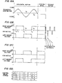
- Crawler movement is accomplished by the eccentric drive motor 150, which on command is energized to rotatably drive its drive shaft 154 and the eccentric 160 connected thereto, whereby the drive arm 164 is reciprocally driven in a rectilinearly fashion between that frame closed position shown in full line and that frame open position shown in dotted line in Figure 9.
- the eccentric drive motor 150 is affixed to one channel 116, whereas the other end of the drive arm 164 is coupled to the other channel 114.
- the drive arm 150 is moved from its position shown in full line to that position as shown in dotted line, traveling a distance of .125 inches.
- a programmable controller 280 alternatively energizes the left upper and lower magnets 104a and 106a, and the right upper and lower magnets 104b and 106b.
- a crawler direction switch 288 is thrown to its clockwise (CW) position 288b, the magnets 104 and 106 are energized as shown in Figure 12B.
- the right upper and lower magnets 104b and 106b are energized, whereas the left upper and lower magnets 104a and 106b are de-energized.
- the drive arm 164 is disposed in that position shown in dotted line in Figure 9 and from time tl to time t3 moves to the right to that position shown in full line in Figure 9, whereby the channel 114 is moved to the right as seen in Figure 9.
- the left upper lower magnets 104a and 106a are energized and the right upper and lower magnets 104a and 106a are de-energized.
- the de-energization and energization of the magnets is done at a time slightly in advance of that time that the drive arm 164 reaches a limit of its travel and reverses direction in order to permit the magnetic field to sufficiently decay in the de-energization magnets and, conversely, the magnetic field to build-up sufficiently to release and to attach the magnets to the inner surface of the shell 14.
- the drive arm 164 is driven by the eccentric drive motor 150 and its eccentric 160 to the right as seen in Figure 9, whereby the channel 116 and, thus, the electromagnetic crawler 10 is moved to the right as shown in Figure 9 and clockwise about the inner peripheral surface of the shell 14 as viewed from the top of the nuclear steam generator 12.
- the signals for controlling the energization and de-energization of the magnets 104 and 106 are provided by the optical switch 174 in response to the rotation of the indicator wheel 170 and its openings 171a and 171b therepast.
- the relative position of the indicator wheel 170 to the eccentric 160 is adjusted to provide the desired timing of energization/de-energization slightly in advance of the reversal of direction of the drive arm 164.
- the programmable controller 280 responds to the signals generated by the optical switch 174 to energize and de-energize the magnets 104 and 106 in a manner shown in Figure 12C, whereby the electromagnetic crawler 10 is directed in a counterclockwise direction about the inner peripheral surface of the shell 14.
- the logic for evaluating the signals derived from the optical switch 174 is generally illustrated in Figure 12D and will be explained below in terms of that program executed by the computer of the programmable controller 280.
- each of the magnets 104 and 106 is energized continuously to maintain the electromagnetic crawler 10 in a stationary position, while de-energizing the eccentric drive motor 150.
- the controlled descent of the electromagnetic crawler 10 is accomplished by reversing the polarity of the energizing voltage applied to the magnets 104 and 106 with a relatively long intermediate hold time at zero voltage.
- counts or set points are entered in a data register to provide a positive going energization between times tl and t2, a relatively long off period between times t2 and t3 and an energization of opposite polarity between the times determined by the set points t3 and t4.
- the reversal with long off time of the magnet energizing voltages reduces the adhesion between the magnets 104 and 106 and the wrapper 24, whereby the electromagnetic crawler 10 is permitted to controllably slide or descend.
- the distance travelled by the electromagnetic crawler 10 about the inner peripheral surface of the shell 14 is measured from the hand hole 30 is determined by manually entering a count in a thumb wheel switch 284 disposed upon the front plate of the programmable controller 280, as seen in Figure 1.
- the set count is loaded into an up/down counter 282 upon actuating a load counter switch 294 as shown in Figures 1 and 13B.
- the optical switch 266 of the azimuth position sensor 110 As the electromagnetic crawler 10 traverses the surface of the shell 14, the optical switch 266 of the azimuth position sensor 110 generates a train of pulses, which are applied to increment and/or decrement the count loaded into the up/down counter 282, depending upon which direction the crawler is moving and which side of the hand hole 30 the electromagnetic crawler 10 is placed.
- the programmable controller 280 brings the electromagnetic crawler 10 to a stop at the desired location.
- the azimuth position sensor 110 includes the roller hub 250 which rotates the gauge wheel 252 as the electromagnetic crawler 10 traverses the shell 14, whereby the openings 254 are rotated past the optical switch 266 to generate the train of signals. In an illustrative embodiment of this invention, each such signal is indicative of 0.125 inch of crawler movement.
- the electromagnetic crawler 10 becomes eschewed with respect to the azimuthal or horizontal direction as it moves about the inner peripheral surface of the shell 14, correction is accomplished by selectively turning off one of the magnets 104 and 106, depending upon the direction of travel and direction of tilt.
- the direction of tilt is indicated by which of the optical'switches 218a or 218b of the tilt sensor 112 is energized. For example, if the electromagnetic crawler 10 is eschewed or tilted at least 2° clockwise as seen in Figure 6, the steel ball 222 will actuate the optical switch 218b. Conversely, if the electromagnetic crawler 10 is tilted counterclockwise, the optical switch 218a will be energized.
- the electromagnetic crawler 10 is moving to the left as seen in Figure 6 or in a counterclockwise direction and the electromagnetic crawler 10 is tilted clockwise as seen in Figure 6, then the lower right magnetic 106b is the leading magnetic and is de-energized.
- the electromagnetic crawler 10 is moving in a counterclockwise direction and is tilted in a counterclockwise direction, then the upper right magnet 104b is the leading magnet and is de-energized for a predetermined interval.
- Figures 13A and B are a diagram of the input/output circuitry interfacing between a microprocessor (not shown) and the various elements of the electromagnetic crawler 10, as explained above.
- the microprocessor may illustratively take the form in a preferred embodiment of this invention of that microprocessor as manufactured by Eagle Signal under their designation of EPTAK-200, and is coupled by a plurality of inputs/outputs (I/O) arrays 310a, b, c, d, e and f to the elements of the electromagnetic crawler 10.
- the I/O array 310 functions as an interface between the microprocessor and a bus 300 coupled to the magnets 104a and b and 106a and b.
- the I/O 310a array comprises some 12 triac output circuits marked 17 to 30. Each such triac circuit is responsive to radiation emitted by a light emitting diode (LED) as directly energized by the microprocessor.
- LED light emitting diode
- Such an I/O array is manufactured by Eagle Signal Company under their designations NL-130 for inputs and NL-140 for outputs. Such an I/O array has been modified to the extent to provide a fast recovery diode coupled in parallel with each triac output circuit to provide a path to dissipate the inductive energy of the magnetic, thus protecting its triac output circuits.
- an I/O 310b interfaces the microprocessor with a bus 302 coupled to energize the eccentric drive motor 150.
- an energizing voltage illustratively plus 24 volts DC, is applied to the eccentric drive motor 150.
- the I/O array 310c is comprised of 8 light emitting diode (LED) circuits and serves to interconnect the left/right switch 286, the crawler direction switch 288, the crawler descent switch 290, the direction reset switch 292 and bus 304, as connected to the optical switches 218a and 218b of the tilt sensor 112, to the microprocessor.
- the I/O array 310d serves to couple the signals set into the thumb wheel switch 284 into the up/down counter 282 when the load counter switch 294 is closed.
- the I/O array 310e couples a signal from the microprocessor instructing the up/down counter 282 to count up (increment) or down (decrement) the count entered therein.
- the I/O array 310f is coupled to that output of the microprocessor indicative of whether the entered count has been decremented/incremented to a predetermined count and, thus, the electromagnetic crawler 10 has reached its selected destination.
- a DC power supply 318 converts the line AC voltage into a regulated DC voltage, illustratively of 24 volts.
- the positive voltage of supply 318 is applied to a conductor 316a, whereas a similar DC power supply 320 provides a negative voltage to the conductor 316b.
- a backup battery BT1 is inserted in circuit by a voltage sensing relay to automatically provide power to magnet 104A. It is understood that the various buses 300, 302, 304, 306 and 308 are included within the power/logic cable 44 coupled to.the electromagnetic crawler 10 as shown in Figures 5 and 6.
- the program to be executed by the microprocessors of the programmable controller 280 will be explained in detail. It is understood that the memory associated with the microprocessor has addressable areas for storing data necessary to effect the program, e.g., data registers, auxiliary registers and controlled relays, as follows:
- DATA data registers
- AUX auxiliary registers
- CR control relays
- the INITIALIZATION subroutine is executed to set the initial status of the control relays and set points in the data registers and auxiliary registers as follows:
- each step of the program begins with a number, e.g., 001 indicating the number of that step in the program, followed by a pneumonic indicating the function to be carried out and concluding with a designation of that data register, auxiliary register or controlled relay in which data is taken from or transferred to.
- step 3 sets the control relay 1.
- the program as executed by the microprocessor of the-programmable controller 280 is comprised of the following subroutines that are repetitively executed in sequence at a rate of 33 Hz.
- the STATIONARY MODE subroutine includes steps 8 to 28 set out as follows:
- the STATIONARY MODE subroutine serves, as indicated above, to apply a positive DC voltage to energize with a constant voltage the magnets 104 and 106, and to de-energize the eccentric drive motor 150, whereby the electromagnetic crawler 10 is attached to the shell 14 in a given position.
- steps 8, 9 and 10 respectively determine whether the counter direction switch 288 and the crawler descent switch 290 are set and, if not, executes in sequence steps 12 through 25 to render conductive triacs 17, 18, 21, 22, 27, 29 and 31, while turning off triacs 19, 20, 23, 24, 25, 28 and 30.
- the result of executing these steps is to apply a positive potential from the power supply 318 to each of the magnets 104a and b, and 106a and b.
- the eccentric drive motor 150 is de-energized.
- the CW MOTION subroutines responds when the CW switch 288b is closed, to alternately turn the left'magnets 104a and 106a and the right magnets 104b and 106b on and off in response to the train of signals from the optical switch 174 (see Fig. 10) associated with the indicator wheel 170 coupled to the eccentric drive motor 150.
- step 29 examines the LED 1 of the I/O array 310c to determine whether the CW switch 288b has been closed.
- step 30 looks at the LED 4 of the I/O array 310c to determine that the up/down counter 282 has not counted out and the control relay 6 is not set to determine that the value of the up/down counter 282 and the preset thumb wheel value, 284, are not equal and, if these conditions are met, the succeeding steps of this subroutine are executed. If not, the program moves to the next COUNTERCLOCKWISE MOTION subroutine.
- step 33 the triac 25 of the I/O array 310b is turned on, i.e., the eccentric drive motor 150 is turned on, before step 34 initializes the direction correction control relay 7 for a single scan.
- Step 35 turns off the triac 31 of the I/O array 310d, to load the count previously entered in the thumb wheel switch 284' into the up/down counter 282.
- step 36 determines whether the left/right switch 286 has been closed. If closed, there is an indication that the electromagnetic crawler 10 has been disposed within the nuclear steam generator 12 to the left of the hand hole 30, and, if open, the electromagnetic crawler 10 has been disposed to the right of the hand hole 30. If disposed to the left, step 38 turns on the triac 26 of the I/O array 310e, whereby the up/down counter 282 is counted up. If disposed to the right, step 41 turns off the triac 26 to count down the counter 282.
- the control relays 1 to 4 are set in the course of the ECCENTRIC WINDOW ORIENTATION subroutine to keep track of the motion of the parallelogram drive frame 102 and to selectively control the energization of the magnets 104 and 106.
- Step 42 examines the LED 003 of the I/O array 310c to determine the presence of an output from the optical switch 174 (see Fig. 10), indicating that one of the openings 171 of the indicator wheel 170 is aligned therewith.
- Step 43 examines whether the control relay 1 is set indicating that the parallelogram drive frame 102 is opening.
- steps 42 and 43 are positive, indicating that the eccentric 160 and its drive arm 164 is at a time tl in its cycle as shown in Figure 12B, steps 45 to 47 respectively turn on triacs 21, 22 and 29, thereby energizing the right upper and lower magnets 104b and 106b, while steps 48 to 50 de-energize triacs 17, 18 and 27, thereby de-energizing the upper and lower left magnets 104a and 106a. If the determinations of steps 42 and 43 are not positive, this subroutine moves to steps 51 and 52 to again determine whether there is an output from the optical switch 174 indicating the passage of an opening 171, and whether the control relay 3 is indicating that the parallelogram drive frame 102 is closing.
- steps 54 to 59 are executed to respectively energize triacs 17, 18 and 27 and to de-energize triacs 21, 22 and 29, whereby the left upper and lower magnets 104a and 106a are energized and the right upper and lower magnets 104b and 106b are de-energized. If these conditions are met, the eccentric 160 and drive arm 164 are disposed at time t2 as shown in Figure 12B.
- the program and, thus, the CW MOTION subroutine is executed some 33 times per second, whereby the position of the indicator wheel 170 is sensed to determine the presence of one of its openings 171a and 171b and the previous setting of the control relays 1 to 4 as set by the ECCENTRIC WINDOW ORIENTATION subroutine, to be explained.
- the outputs from the optical switch 174 and the condition of the control relays 1 to 4 positively indicates the position of the drive 164 and the movement of the parallelogram drive frame 102.
- COUNTERCLOCKWISE (CCW) MOTION subroutine is executed, set out as follows:
- the CCW MOTION subroutine examines the position of the indicator wheel 170 and the control registers 1 to 4 to energize the left and right magnets 104 and 106, in a similar manner to the CW MOTION subroutine, explained above. In summary, the CCW MOTION subroutine determines when the CCW switch 288a is closed (step 60) and the up/down counter 282 has not counted out (step 61) to alternatively energize the left and right magnets as shown in Figure 12C.
- the CCW MOTION subroutine energizes the eccentric drive motor 150 (step 64), transfers the count set from the thumb wheel switch 284 into the up/down counter 282 (step 66), commands the up/down counter 282 to count down if the electromagnetic crawler 10 is located on the left side of the hand hole 30 (steps 67 and 69) or up if on the right side (steps 70 and 72), and alternatively energizes the left magnets, while de-energizing the right magnets (steps 76 to 81), or energizes the right magnets, while de-energizing the left magnets (steps 85 to 90).
- the AFTER COUNT-OUT subroutine monitors the LED 04 of the I/O array 310f to sense when the up/down counter 282 has counted out, indicating that the electromagnetic crawler 10 has moved to its selected location.
- This subroutine includes the following steps:
- Step 91 monitors the LEp,04 of the I/O array 310f and if it is on, the following steps 93 to 100 are executed; if not, the program jumps to the following ECCENTRIC WINDOW ORIENTATION subroutine.
- Steps 93 to 98 renders conductive triacs 17, 18, 21, 22, 27 and 29 of the I/O array 310a, whereby each of the magnets 104a and b, and 106a and b is energized to secure the electromagnetic crawler 10 to the shell 14.
- step 99 sets on the control relay 6 indicating that the azimuth or up/down counter 282 has counted out, before step 100 turns off the triac 25 of the I/O array 310b, thus de-energizing the eccentric drive 150.
- the ECCENTRIC WINDOW ORIENTATION subroutine sets the control registers 1 to 4 in response to signals from the optical switch 174 as indicating the passage of one of the openings 171a and 171b of the indicator wheel 170.
- the status of the control relays 1 to 4 is illustrated in Figure 12D as a function of the relative position of the drive arm 164 in its cycle, as shown in Figure 12A.
- the digital signals set into the control relays 1 to 4 identify four distinct zones or phases of the movement of the drive arm 164 and, thus, position of the parallelogram drive frame 102.
- the control relays 1 to 4 are set under the control of the ECCENTRIC WINDOW ORIENTATION subroutine, which is set out as follows:
- step 104 sets on the control relay 2 and step 105 sets off the control relay 4 indicating that the parallelogram drive frame 102 is closing and that one of the openings 171a and 171b is not aligned with the optical switch 174. If the condition sensed by steps 101 and 102 are not both met, the ECCENTRIC WINDOW ORIENTATION subroutines jumps 2 steps to steps 106 and 107, which respectively determines the presence of the output from the optical switch 174 and whether the control relay is set on.
- control relay 3 is set on and the control relay 1 is set off, indicating that the parallelogram drive frame 102 is opening. If not, this subroutine jumps to steps 111 and 112, which respectively determine the absence of a signal from the optical switch 174, and whether the control relay 3 is set on. If both of these conditions are met, the control relay 4 is set on and the control relay 2 is set off, indicating that the parallelogram drive frame 102 is closing.
- this subroutine jumps to steps 117 and 118 to determine whether the control relay 4 is set on and the presence of an output signal from the optical switch 174, to respectively set on the control relay 1 and set the control relay 3 off, thus indicating that the parallelogram drive frame 102 is opening and that one of the openings 171a and 171b is aligned with 'its optical switch 174.
- steps 101 to 120 sequentially review the control relays 1 to 4 and determine the presence or absence of an output from the optical switch 174 to respectively set on and off the control relays 1 to 4.
- the control relays may be set in four distinct combinations to identify where the drive arm 164 is disposed at any instant of time in its cycle of movement.
- the DESCENT MOTION subroutine controls the descent of the electromagnetic crawler 10 by applying repetitive voltages of opposite polarity to the magnets 104 and 106 and providing a relatively long intermediate period therebetween of substantially zero voltage. As a result, the adhesion between the magnets 104 and 106 and the shell 14 is reduced, permitting the electromagnetic crawler 10 to slide controllably down the peripheral surface of the shell 14.
- the voltage waveform as applied to the magnets 104 and 106 is illustrated in Figure 12B under the heading of "Descent Motion". Briefly, the times of energization and de-energization are set by initializing set points in the magnets on/off data registers 1 to 4, as indicated in Figure 12B.
- An index data register 6 is incremented as a function of time and is compared with each of the magnets on/off data registers 1 to 4 and, upon detecting a match therebetween, a corresponding voltage is applied or removed from the magnets 104 and 106.
- the magnets 104 and 106 are cycled at a rate of 160 times per minute during a horizontal movement and approximately 300 times per minute during a vertical descent.
- the cyclical energization and de-energization of the magnets 104 and 106 during horizontal movement of the electromagnetic crawler 10 and, thus, the horizontal speed of the electromagnetic crawler 10 is determined by the RPM of the eccentric drive motor 150.
- the cyclical energization and de-energization of the magnets 104.and 106 during the DESCENT MOTION subroutine is controlled, as will be described below, by the points in the data registers 1 to 4 and the rate at which the entire program is executed.
- the set points and program execution rate are determined empirically to control the cycle time of energizing the magnets 104 and 106, as shown in Figure 12B, as a function of the friction coefficient between the magnets 104 and 106 and the surface of the shell 14, and the rate of flux field increase and decrease in the magnets 104 and 106.
- Step 121 examines the LED 05 of the I/O array 310c to determine whether the crawler descent switch 290 is closed to command a descent or downward motion of the electromagnetic crawler 10. If not, the program jumps in step 122 to the next DIRECTION CORRECTION subroutine. If closed, steps 123 and 124 compare the counts stored in an actual count data register 8 with the initialized count in data register 1. In the INITIALIZATION subroutine, the magnets on/off data registers 1, 2, 3 and 4 were loaded with set points or counts controlling the times for turning on and off the magnets 104 and 106 as shown in Figure 12B.
- the actual count data register 8 is used as a counter that is indexed each time the DESCENT MOTION subroutine is executed, realizing that the entire program requires 30 milliseconds to execute and is executed some 33 times per second. If the count in the actual count data register 8 is greater than that count stored in the magnets on date register 1, the DESCENT MOTION subroutine jumps to step 312. Otherwise, steps 126 to 131 are executed to turn on the triacs 17, 18, 21, 22, 27 and 29 of the I/O array 310a, whereby each of the magnets 104 and 106 is turned on at a point time determined by the count placed in the magnets/on data register 1.
- steps 132 and 133 the index count in the actual count data register 8 is compared with that stored data in the magnets/off register 2 and, if greater, the DESCENT MOTION subroutine moves to steps 141 and 142. Otherwise, in steps 135 to 140, the triacs 17, 18, 21, 22, 27 and 29 are rendered non-conductive and the magnets 104 and 106 are de-energized.
- steps 141 and 142 compares the index count in the actual count data register 8 with that count initialized in the magnets/on data register 3 and, if greater, the DESCENT MOTION subroutine jumps to steps 150 and 151; if not, steps 144 to 149 renders the triacs 19, 20, 23, 24, 28 and 30 conductive, whereby a negative voltage is applied to the magnets 104 and 106.
- steps 150 and 151 compare the index count of the actual count data register 8 with the initialized count of the magnets/off data register 4 and, if greater, the DESCENT MOTION subroutine jumps to step 159.
- steps 153 to 158 turn off the triacs 19, 20, 23, 24, 28 and 30, whereby the energizing voltage is removed from the magnets 104 and 106.
- steps 159 and 160 compare the initialized count, e.g., 21, stored in data register 7 with the current count in the actual count data register 8 and if equal, indicating a completion of a cycle, the index data register 8 is reset by transferring a zero thereto from data register 5. If a cycle is not complete, step 164 adds a one as stored in the data register 6 to the index data register 8.
- the DIRECTION CORRECTION subroutine sets or resets the movement of the electromagnetic crawler 10 to correspond with the setting of the CW or CCW switches 288b and 288a in response to the closing of the direction reset switch 292.
- the sense of direction maintained by the programmable controller 280 as to whether the electromagnetic crawler 10 is moving in a counterclockwise or clockwise direction about the peripheral of the shell 14, may become lost. This sense of direction is determined by the relative relationship between the openings 171a and 171b of the indicator wheel 170 and the position of the drive arm 164, i.e., whether the parallelogram drive frame 102 is opening or closing.
- the DIRECTION CORRECTION subroutine responds to the closing of the direction reset switch 292 to reset the control relay 7.
- the steps of the DIRECTION CORRECTION subroutine are set out as follows:
- step 167 examines the LED 09 of the I/O array 310c to determine whether the direction reset switch 292 has been closed and, if not, the program jumps 20 steps to continue the program with the execution of the TILT CORRECTION subroutine. If closed, the direction subroutine then proceeds to examine the control relays 1 to 4 and to reverse the setting of the direction correction control relay 7 based upon the current condition thereof. In particular, steps 169, 170 and 171 determine whether the control relays 1, 2 and 7 are set on and, if not, the subroutine jumps five instructions. If on, steps 173 and 174 set on control relays 3 and 4 and off control relays 1, 2 and 7.
- Steps 178 to 180 determine whether control relays 2, 3 and 7 are on and, if so, sets on control relays 1 and 4 and off control relays 2, 3 and 7.
- Steps 187 to 189 determine whether control relays 3, 4 and 7 are on and, if so, sets on control relays 1 and 2 and off control relays 3, 4 and 7.
- steps 196 to 198 determine whether control relays 1, 4 and 7 are on and, if so, sets on control relays 2 and 3 and off control relays 1, 4 and 7.
- the TILT CORRECTION subroutine responds to the tilt sensor 112 to selectively adjust the direction of movement of the electromagnetic crawler 10 depending upon its direction of travel, i.e., clockwise or counterclockwise, about the periphery of the shell 14 as viewed from the top of the nuclear steam generator 12, and the direction of tilt, i.e., a clockwise or counterclockwise tilt with respect to vertical as seen in Figure 6.
- the leading magnet on the trailing side of the electromagnetic crawler 10 is turned off when the tilt sensor 112 indicates that the electromagnetic crawler 10 is moving on a non-horizontal path or a predetermined time period has expired, whichever occurs first.
- the TILT CORRECTION subroutine responds to the interruption of one of the optical switches 218a or 218b to initiate indexing of the index auxiliary register 2, understanding that the count stored therein is incremented with each repetitive execution of the program.
- the count retained in the index auxiliary register 2 equals the initialized count in the start tilt correction auxiliary register 5
- a selected one of the four magnets 104a and b, and 106a and b is turned off to start the correction.
- the index auxiliary register 2 is reset to zero and the de-energized magnet is turned back on.
- the index auxiliary register 2 reaches a count as stored in the stop tilt correction auxiliary register 4 before the signal from the optical switch 218a or 218b is removed, the index auxiliary register 2 is reset and the de-energized magnet turned back on.
- the stop tilt correction auxiliary register 4 serves as a backup to prevent over correction if one of the optical switches 218a or 218b fails to operate correctly.
- the auxiliary registers 1 to 5 are used to time the functions of the TILT CORRECTION subroutine. After one of the optical switches 218a and 218b provides an output signal indicating a tilt in one direction or the other, the actual count auxiliary register 3 is incremented with each cycle of the program.
- the CCW tilt correction control relay 8 and the CW tilt correction control relay 9 are initially set-off. When the actual count auxiliary register 3 has been incremented to a predetermined count corresponding to an interval to permit the programmable controller 280 to ignore momentary jars to the electromagnetic crawler 10, the CCW tilt correction control relay 8 and the CW tilt correction control relay 9 are set on and a selected magnet is de-energized dependent upon the direction of travel of the electromagnetic crawler 10 and the direction of tilt.
- the program will repetitively cycle through the TILT CORRECTION subroutine without taking action until one of the optical switches 218a and 218b of the tilt sensor 112 provides an output signal indicative of a corresponding tilt of the electromagnetic crawler 10. If there is a clockwise tilt from the vertical as seen in Figure 6, the optical switch 218b provides an output signal via the bus 304 to energize the LED 108. If there is a counterclockwise tilt, the optical switch 218a provides a signal via the bus 304 to energize the LED 07 of the I/O array 310c.
- steps 229, 230 and 231 sense that either of the CCW direction switch 288a or CW direction switch 288b have been closed and that a signal is received from the optical switch 218a, to index by one the actual count auxiliary register 3.
- step 239 sets on the CCW tilt correction control relay 8.
- steps 240, 241 and 242 determine that one of the CCW direction switch 288a and CW direction switch 288b has been thrown and that a signal is output by the optical switch 218b to increment in step 246 the actual count of the auxiliary register 3.
- step 250 sets the CW tilt correction control relay 9.
- Steps 205, 206 and 207 examine the LED's 07 and 01, and the CCW tilt correction control relay 8 to determine that the clockwise direction switch 288b has been closed, that the output signal from the optical switch 218a is received and that the CCW tilt correction control relay 8 has been set to energize in step 209 a triac 32 (not shown) to indicate that a tilt correction in process and in step 210 to turn off the triac 27, thereby de-energizing the lower left magnet 106a.
- step 205, 206 and 207 If the conditions tested by steps 205, 206 and 207 are not met, the subroutine jumps to steps 211, 212 and 213, which determines that the optical switch 218a outputs a signal, the CCW direction switch 288a is closed and that the CCW tilt correction control relay 8 is set to thereby provide in step 215 an indication that a tilt correction is in process and to de-energize in step 216 the upper right magnet 104b.
- the TILT CORRECTION subroutine continues in steps 217, 218 and 219 to sense that the output from the optical switch 218b, that the CW direction switch 288b is closed and that the CW tilt correction control relay is set to provide an indication that a tilt correction is in process and to de-energize in step 222 the upper left magnet 104a.
- steps 223, 224 and 22S the presence of the output signal from the optical switch 218b is sensed, the closing of the CCW direction switch 288a is sensed and the setting of the CW tilt correction control relay 9 is sensed to provide in step 227 an indication that the tilt correction process is occurring and to turn off in step 228 the lower right magnet 106b.
- steps 233 to 239 increment by one the actual count auxiliary register for each execution of the TILT CORRECTION subrouting and compares that current count with that count initially stored in the start tilt correction auxiliary register 5. If greater, the CCW tilt correction control relay 8 is set.
- Steps 240 to 248 sense the presence of the output signal from the optical switch 218b to index the actual count auxiliary register 3 and to determine whether the delay period is over and, if so, to set the CW tilt correction control relay 9.
- Steps 251 and 252 determine whether tilt correction has occurred for a predetermined period, e.g., 600 cycles of program execution, and, if that period has expired, the actual count auxiliary register 3 is reset to zero and the CCW tilt correction relay 8 and the tilt correction relay 9 are set off, before step 259 effects a return to the initial program step, thus permitting continuous re-execution of the program.
- a predetermined period e.g. 600 cycles of program execution
Landscapes
- Engineering & Computer Science (AREA)
- Mechanical Engineering (AREA)
- Physics & Mathematics (AREA)
- Chemical & Material Sciences (AREA)
- Combustion & Propulsion (AREA)
- Transportation (AREA)
- High Energy & Nuclear Physics (AREA)
- Thermal Sciences (AREA)
- General Engineering & Computer Science (AREA)
- Monitoring And Testing Of Nuclear Reactors (AREA)
- Control Of Position Or Direction (AREA)
- Selective Calling Equipment (AREA)
Applications Claiming Priority (2)
| Application Number | Priority Date | Filing Date | Title |
|---|---|---|---|
| US687237 | 1984-12-28 | ||
| US06/687,237 US4703817A (en) | 1984-12-28 | 1984-12-28 | Controllable vehicle for inspecting limited access areas |
Publications (2)
| Publication Number | Publication Date |
|---|---|
| EP0186488A2 true EP0186488A2 (de) | 1986-07-02 |
| EP0186488A3 EP0186488A3 (de) | 1987-07-01 |
Family
ID=24759618
Family Applications (1)
| Application Number | Title | Priority Date | Filing Date |
|---|---|---|---|
| EP85309405A Withdrawn EP0186488A3 (de) | 1984-12-28 | 1985-12-23 | Ferngesteuerte bewegbare Vorrichtung zur Inspektion von Gebieten mit beschränkter Zugänglichkeit |
Country Status (3)
| Country | Link |
|---|---|
| US (1) | US4703817A (de) |
| EP (1) | EP0186488A3 (de) |
| JP (1) | JPS61160367A (de) |
Cited By (2)
| Publication number | Priority date | Publication date | Assignee | Title |
|---|---|---|---|---|
| FR2607421A1 (fr) * | 1986-12-01 | 1988-06-03 | Electricite De France | Dispositif d'exploration et/ou de traitement d'une surface lisse courbe |
| EP2401117A4 (de) * | 2009-02-27 | 2017-08-09 | R. Brooks Associates, Inc. | Prüfsystem und prüfverfahren mit einem magnetischen prüffahrzeug |
Families Citing this family (3)
| Publication number | Priority date | Publication date | Assignee | Title |
|---|---|---|---|---|
| US5852984A (en) * | 1996-01-31 | 1998-12-29 | Ishikawajimi-Harima Heavy Industries Co., Ltd. | Underwater vehicle and method of positioning same |
| US5884642A (en) * | 1997-08-07 | 1999-03-23 | Broadbent Spray Rentals | Remotely controlled pressurized liquid dispensing mobile unit |
| BRPI0410902A (pt) * | 2003-06-02 | 2006-06-27 | Brooks R Ass Inc | método e aparelho para inspeção de componentes de cabeçote de reator |
Family Cites Families (19)
| Publication number | Priority date | Publication date | Assignee | Title |
|---|---|---|---|---|
| US1715745A (en) * | 1927-07-22 | 1929-06-04 | Morton H Edmondson | Traction mechanism |
| SE309562B (de) * | 1965-05-14 | 1969-03-24 | S Swallert | |
| US3407749A (en) * | 1966-08-31 | 1968-10-29 | Gen Motors Corp | Motor for propulsion and load support |
| US3430277A (en) * | 1967-05-25 | 1969-03-04 | Robert Ortega | Automatic vacuum pool cleaner |
| AT336926B (de) * | 1972-12-22 | 1977-06-10 | Siemens Ag | Inspektions- und reparatureinrichtung fur dampferzeuger |
| US3811320A (en) * | 1973-03-12 | 1974-05-21 | Rockwell International Corp | Surface scaler apparatus |
| US3913452A (en) * | 1973-08-01 | 1975-10-21 | Combustion Eng | Remotely movable platform |
| US3911750A (en) * | 1974-02-04 | 1975-10-14 | Babcock & Wilcox Co | Apparatus for the internal inspection of tubular conduits |
| US4216893A (en) * | 1977-03-08 | 1980-08-12 | Westinghouse Electric Corp. | Apparatus for remotely repairing tubes in a steam generator |
| US4205939A (en) * | 1978-01-30 | 1980-06-03 | Westinghouse Electric Corp. | Apparatus for remotely repairing tubes in a steam generator |
| US4205940A (en) * | 1978-03-21 | 1980-06-03 | Westinghouse Electric Corp. | Apparatus for remotely repairing tubes in a steam generator |
| US4213732A (en) * | 1978-04-13 | 1980-07-22 | Westinghouse Electric Corp. | Apparatus for remotely repairing tubes in a steam generator |
| US4231419A (en) * | 1978-07-21 | 1980-11-04 | Kraftwerk Union Aktiengesellschaft | Manipulator for inspection and possible repair of the tubes of heat exchangers, especially of steam generators for nuclear reactors |
| FR2437341A1 (fr) * | 1978-09-29 | 1980-04-25 | Commissariat Energie Atomique | Vehicule apte a se deplacer avec adherence sur une surface quelconque |
| US4247974A (en) * | 1978-10-18 | 1981-02-03 | Westinghouse Electric Corp. | Set-up method for steam generator tube installation apparatus |
| SU844452A1 (ru) * | 1979-03-30 | 1981-07-07 | Государственный Научно-Исследовательскийинститут Машиноведения Им.A.A.Благо-Hpaboba | Транспортное средство повышеннойпРОХОдиМОСТи |
| US4287655A (en) * | 1979-04-30 | 1981-09-08 | Westinghouse Electric Corp. | End effector position and identification system for steam generator servicing machine |
| FR2466766A1 (fr) * | 1979-09-27 | 1981-04-10 | Commissariat Energie Atomique | Dispositif d'entrainement pour sonde de controle de tubes |
| US4368644A (en) * | 1981-05-26 | 1983-01-18 | Combustion Engineering, Inc. | Tool for inspecting defects in irregular weld bodies |
-
1984
- 1984-12-28 US US06/687,237 patent/US4703817A/en not_active Expired - Fee Related
-
1985
- 1985-12-23 EP EP85309405A patent/EP0186488A3/de not_active Withdrawn
- 1985-12-27 JP JP60293356A patent/JPS61160367A/ja active Pending
Cited By (4)
| Publication number | Priority date | Publication date | Assignee | Title |
|---|---|---|---|---|
| FR2607421A1 (fr) * | 1986-12-01 | 1988-06-03 | Electricite De France | Dispositif d'exploration et/ou de traitement d'une surface lisse courbe |
| EP0274925A1 (de) * | 1986-12-01 | 1988-07-20 | Electricite De France | Vorrichtung zur Exploration und/oder Behandlung einer ebenen runden Fläche |
| US4883576A (en) * | 1986-12-01 | 1989-11-28 | Electricite De France (Service National) | Apparatus for survey and/or treatment of a smooth, curved surface |
| EP2401117A4 (de) * | 2009-02-27 | 2017-08-09 | R. Brooks Associates, Inc. | Prüfsystem und prüfverfahren mit einem magnetischen prüffahrzeug |
Also Published As
| Publication number | Publication date |
|---|---|
| US4703817A (en) | 1987-11-03 |
| JPS61160367A (ja) | 1986-07-21 |
| EP0186488A3 (de) | 1987-07-01 |
Similar Documents
| Publication | Publication Date | Title |
|---|---|---|
| US3987666A (en) | Device for remote inspection and testing of a structure | |
| JPS5874283A (ja) | マニピユレ−タ溶接装置用イメ−ジ検出装置 | |
| EP0054798B1 (de) | Positionierungseinheit für Röntgen-Tomographie-Geräte | |
| US5204622A (en) | Improved probe for inspecting tubes having mechanism for maintaining alignment of probe axis of rotation | |
| US4249810A (en) | Pipeline inspection apparatus | |
| US4703817A (en) | Controllable vehicle for inspecting limited access areas | |
| DE69318600D1 (de) | On-line-Ersetzen eines Moduls in einer Datenverarbeitungsanlage mit mehreren Modulen | |
| KR102359154B1 (ko) | 전력설비 자율진단 로봇 | |
| EP0178930A1 (de) | Abbildungs- und Schweisseinrichtung für einen Schweissroboter | |
| US4661309A (en) | Equipment transporter for nuclear steam generator | |
| JPH0630855B2 (ja) | 人体に有害な環境で作業するツール保持ロボットの配置方法 | |
| US5164151A (en) | Manipulator system for an enclosure with a limited access point | |
| JP2651382B2 (ja) | 構造物の検査装置 | |
| EP3798622A1 (de) | Systeme und verfahren zur inspektion von rohrleitungen unter verwendung eines robotischen bildgebungssystems | |
| CN111683225A (zh) | 一种多视角摄像头及多路视频信号处理方法和模块 | |
| EP0047047B1 (de) | Dekontaminationseinrichtung für nukleare Dampferzeuger | |
| US5544206A (en) | Reactor head work station | |
| Kepplin et al. | A mechatronic concept for a sewer inspection robot | |
| CN209607424U (zh) | 核电厂钢制安全壳焊缝自动检查装置 | |
| RU2123683C1 (ru) | Способ неразрушающего контроля качества кольцевых сварных швов магистральных трубопроводов | |
| JP2525057B2 (ja) | 配管自動検査装置 | |
| SU1132136A1 (ru) | Установка дл контрол за состо нием футеровки канала индукционной плавильной печи | |
| JPS63191998A (ja) | 炉心確認用テレビカメラ装置 | |
| CA2084391A1 (en) | Process and device for the positioning of a tool in relation to the axis of a tube, especially for a steam generator of a nuclear reactor | |
| CN109494599A (zh) | 用于多种配电设备的智能巡检的微型导轨系统及巡检方法 |
Legal Events
| Date | Code | Title | Description |
|---|---|---|---|
| PUAI | Public reference made under article 153(3) epc to a published international application that has entered the european phase |
Free format text: ORIGINAL CODE: 0009012 |
|
| AK | Designated contracting states |
Kind code of ref document: A2 Designated state(s): BE CH FR GB IT LI SE |
|
| PUAL | Search report despatched |
Free format text: ORIGINAL CODE: 0009013 |
|
| AK | Designated contracting states |
Kind code of ref document: A3 Designated state(s): BE CH FR GB IT LI SE |
|
| 17P | Request for examination filed |
Effective date: 19871229 |
|
| 17Q | First examination report despatched |
Effective date: 19880908 |
|
| STAA | Information on the status of an ep patent application or granted ep patent |
Free format text: STATUS: THE APPLICATION IS DEEMED TO BE WITHDRAWN |
|
| 18D | Application deemed to be withdrawn |
Effective date: 19890119 |
|
| RIN1 | Information on inventor provided before grant (corrected) |
Inventor name: PLANCK, NORMAN ALBERT Inventor name: HALL, WILLIAM GARDNER Inventor name: STONER, RONALD RUSSELL Inventor name: SENGER, ROBERT DEAN |