EP0186513A2 - Procédé pour commander un cycloconvertisseur et dispositif approprié - Google Patents
Procédé pour commander un cycloconvertisseur et dispositif approprié Download PDFInfo
- Publication number
- EP0186513A2 EP0186513A2 EP85309478A EP85309478A EP0186513A2 EP 0186513 A2 EP0186513 A2 EP 0186513A2 EP 85309478 A EP85309478 A EP 85309478A EP 85309478 A EP85309478 A EP 85309478A EP 0186513 A2 EP0186513 A2 EP 0186513A2
- Authority
- EP
- European Patent Office
- Prior art keywords
- cycloconverter
- current
- load
- control
- output
- Prior art date
- Legal status (The legal status is an assumption and is not a legal conclusion. Google has not performed a legal analysis and makes no representation as to the accuracy of the status listed.)
- Granted
Links
Images


Classifications
-
- H—ELECTRICITY
- H02—GENERATION; CONVERSION OR DISTRIBUTION OF ELECTRIC POWER
- H02M—APPARATUS FOR CONVERSION BETWEEN AC AND AC, BETWEEN AC AND DC, OR BETWEEN DC AND DC, AND FOR USE WITH MAINS OR SIMILAR POWER SUPPLY SYSTEMS; CONVERSION OF DC OR AC INPUT POWER INTO SURGE OUTPUT POWER; CONTROL OR REGULATION THEREOF
- H02M7/00—Conversion of AC power input into DC power output; Conversion of DC power input into AC power output
- H02M7/66—Conversion of AC power input into DC power output; Conversion of DC power input into AC power output with possibility of reversal
- H02M7/68—Conversion of AC power input into DC power output; Conversion of DC power input into AC power output with possibility of reversal by static converters
- H02M7/72—Conversion of AC power input into DC power output; Conversion of DC power input into AC power output with possibility of reversal by static converters using discharge tubes with control electrode or semiconductor devices with control electrode
- H02M7/75—Conversion of AC power input into DC power output; Conversion of DC power input into AC power output with possibility of reversal by static converters using discharge tubes with control electrode or semiconductor devices with control electrode using devices of a thyratron or thyristor type requiring extinguishing means
- H02M7/757—Conversion of AC power input into DC power output; Conversion of DC power input into AC power output with possibility of reversal by static converters using discharge tubes with control electrode or semiconductor devices with control electrode using devices of a thyratron or thyristor type requiring extinguishing means using semiconductor devices only
- H02M7/7575—Conversion of AC power input into DC power output; Conversion of DC power input into AC power output with possibility of reversal by static converters using discharge tubes with control electrode or semiconductor devices with control electrode using devices of a thyratron or thyristor type requiring extinguishing means using semiconductor devices only for high voltage direct transmission link
-
- Y—GENERAL TAGGING OF NEW TECHNOLOGICAL DEVELOPMENTS; GENERAL TAGGING OF CROSS-SECTIONAL TECHNOLOGIES SPANNING OVER SEVERAL SECTIONS OF THE IPC; TECHNICAL SUBJECTS COVERED BY FORMER USPC CROSS-REFERENCE ART COLLECTIONS [XRACs] AND DIGESTS
- Y02—TECHNOLOGIES OR APPLICATIONS FOR MITIGATION OR ADAPTATION AGAINST CLIMATE CHANGE
- Y02E—REDUCTION OF GREENHOUSE GAS [GHG] EMISSIONS, RELATED TO ENERGY GENERATION, TRANSMISSION OR DISTRIBUTION
- Y02E60/00—Enabling technologies; Technologies with a potential or indirect contribution to GHG emissions mitigation
- Y02E60/60—Arrangements for transfer of electric power between AC networks or generators via a high voltage DC link [HVCD]
-
- Y—GENERAL TAGGING OF NEW TECHNOLOGICAL DEVELOPMENTS; GENERAL TAGGING OF CROSS-SECTIONAL TECHNOLOGIES SPANNING OVER SEVERAL SECTIONS OF THE IPC; TECHNICAL SUBJECTS COVERED BY FORMER USPC CROSS-REFERENCE ART COLLECTIONS [XRACs] AND DIGESTS
- Y02—TECHNOLOGIES OR APPLICATIONS FOR MITIGATION OR ADAPTATION AGAINST CLIMATE CHANGE
- Y02P—CLIMATE CHANGE MITIGATION TECHNOLOGIES IN THE PRODUCTION OR PROCESSING OF GOODS
- Y02P80/00—Climate change mitigation technologies for sector-wide applications
- Y02P80/10—Efficient use of energy, e.g. using compressed air or pressurized fluid as energy carrier
Definitions
- the present invention relates to a cycloconverter system of the circulating current type to deliver a variable frequency ac current to a single- or polyphase load.
- a cycloconverter is an apparatus to directly convert an ac power having a constant frequency into an ac power having a different frequency.
- the drawback with the cycloconverter is that it is necessary to communicate thyristors serving as elements constituting the cycloconverter by a power supply voltage, with the result that a large reactive power is produced from a power source. Further, the reactive power always varies in synchronism with a frequency on the side of a load. As a result, this not only allows the capacity of a power system equipment to be increased, but also gives various bad influences on electric equipment connected to the same system.
- a reactive power compensative cycloconverter as disclosed in the Japanese Publication Tokkaisho No. 56-44382 etc. is proposed to solve the above-mentioned problem. Namely, a cycloconverter of the circulating current type is used to connect a power factor compensating capacitor at a receiving-end of the cycloconverter, thus to control a circulating current of the cycloconverter so that a leading reactive power by the power factor compensating capacitor and a lagging reactive power by the cycloconverter are cancelled with each other.
- the role of a reactive power compensating device which has been needed in the prior art is rendered to the cycloconverter itself. As a result, the conventional reactive power compensating device is not need. According to this, the cycloconverter can be snail-sized and lightened, and its cost can be reduced.
- the capacity of a power factor compensating capacitor at the receiving-end is determined as a standard when the cycloconverter effects a rated operation.
- a power factor compensating capacitor having a capacity to cope therewith is necessary to provide for in advance a power factor compensating capacitor having a capacity to cope therewith.
- an output capacity of the cycloconverter is determined by the capacity of the power factor compensating capacitor, with the result that an overload running which requires a capaciti above the capacity of the lead capacitor is impossible.
- an object of the present invention is to provide a control method for a cycloconverter of the circulating current type and a control apparatus therefor which makes it possible to effect a stabilized overload operation without increasing the capacity of a power factor corpensating capacitor.
- an overload operation is carried cut wherein a reactive power control is effected so that an input power factor is equal to unity until a rated load. Accordingly, it is sufficient to provide for a power factor compensating capacitor having a capacity enough to cancel a lagging reactive power given by the cycloconverter at the tire of the rated operation.
- the reactive power control at a receiving-end is ceased to effect a control such that a minimum circulating current is continued to flow in the cycloconverter.
- FIG. 1 there-is shown, in a block form, a first preferred embodiment of a cycloconverter system according to the present invention.
- the cycloconverter system including a power supply line BUS of a three phase power supply, a power factor compensating capacitor assembly CAP comprising delta or star connected capacitors, a power transformer TR, a cycloconverter CC of the circulating current type, and a load LOAD.
- the cycloconverter CC comprises a positive group converter SSP, a negative group converter SSN, and dc reactors L 01 and L 02 with intermediate taps.
- a control circuit for the cycloconverter CC comprises a load current detector CTL, an output current detector CT P of the positive group converter, an output current detector CT N of the negative group of the converter, a transformer PT S for detecting a three phase ac voltage at a receiving-end, a current transformer CT S for detecting a three-phase ac current, a reactive power computing circuit VAR, comparators C 1 , C 2 and C 3 , adders A 1 , A 2 and A3, control compensating circuits H 2 (S), G O (S) and G L (S), a limiter circuit LIM, a circulating current setter VR O , an operational amplifier K 1 and phase control circuits PHP and PHN.
- the error ⁇ 3 is input to the load current control compensating circuit G L (S) to carry cut proportional amplification or integral amplification.
- an output voltage V N of the negative group converter SSN is expressed as where K V denotes a conversion constant, V S a power supply voltage, and ⁇ P and a N firing phase angles.
- the error ⁇ 3 varies according to this. Accordingly, the above-mentioned firing phase angles ⁇ P and ⁇ N are controlled in a manner that a sinewave current I L flows in the load. In such an ordinary operation, the voltages of the positive group converter SSP and the negative group converter V N are balanced with each other, with the result that little circulating current I O flows.
- the circulating current I O of the cycloconverter is detected as follows.
- the circulating current I O is determined by obtaining the sum of a value detected of the output current I of the positive group converter SSP to a value detected of the output current I L of the negative converter SSN, subtracting an absolute value of a value detected of the load current I L from the sum, and multiplying it by one-half.
- the relationship is expressed as follows:
- the circulating current I O thus obtained is compared with the command value I*.
- the error ⁇ 2 undergoes proportional amplification or integral amplification.
- an output signal of the circulating current control compensating circuit G O (S) is input to the adders A 2 and A 3 .
- the reactive power control is carried out as follows.
- the three phase current detector CT S and the three phase voltage detector PT S are provided.
- the reaction power Q is computed by the reactive power computating circuit VAR.
- the command value Q * for the reactive power control is ordinarily set at zero.
- the reactive power control compensating circuit H O (S) ordinarily employs integral element in order to allow the steady-state error ⁇ 1 to be zero. By passing an output from the control compensating circuit H O (S) through the adder A 1 , the above-mentioned circulating current command value I O * is obtained.
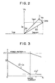
- Fig. 2 is a view showing the relationship between voltage and current vectors at the receiving-end wherein the vector relationship represents a single-phase of the three phase power supply.
- V S represents a power supply voltage
- I cap a leading current flowing in the power factor compensating capacitor
- I CC an input current of the cycloconverter
- I S an effective value of the input value
- I REACT a reactive value of the I S .
- I SS p and I SSN represent input currents of the positive and negative group converters, respectively. Where a current conversion factor of the converter is denoted by K 1 , the above-mentioned input currents I SS p and I SSN are expressed as follows: and
- This vector view indicates the condition where the load current I L is delivered from the positive group converter SSP.
- the input current I CC of the cycloconverter is obtained as the vector sum of the input currents I CC and I SSP .
- the effective value I S and the reactive value I REACT of the input current Ice can be expressed as follows: where the relationship of ⁇ N ⁇ 180- ⁇ P is introduced in the above deviation. Namely, the circulating current I O flowing in the cycloconverter does not affect the effective value I S on the input side, but affects the reactive value I REACT .
- the current I S delivered from the power supply always becomes effective component, thus maintaining the fundamental wave power factor at unity.
- Fig. 3 represents the relationship of the load current I O versus the circulating current I O and the power factor P.F.
- Another circulating command value ⁇ I O * is given by a circulating current setter VR O .
- the current command value ⁇ I O * is set at a value such that circulating current of the cycloconverter CC is not interrupted.
- An actual circulating current I O is controlled in accordance with the output of the adder.
- the power factor at the receiving-end is not equal to unity. Accordingly, according as the load current I L increases, there occurs a condition where the power factor lags. This is no problem in the system where the overload running is seldom carried out.
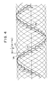
- Fig. 4 shows an output voltage waveform of a cycloconverter of the circulating current type having twelve control phases when the setting is nade such that an output frequency f 0 is 1.2 times larger than an input frequency f 1 .
- V 1 (this solid line) represents an input voltage
- V P (thick single dotted lines) an output voltage of the positive group converter
- V N (thick double dotted lines) an output voltage of the negative group converter
- V R thick dotted lines
- V 0 thin solid line
- the output voltage V O is obtained as an average of the output voltages V P and VN and represents a stair-stepped waveform.
- the output voltages V P and V N are created by connecting portions (segments) of the input voltage Vi to each other, respectively.
- the normal operating mode of the cycloconverter of the circulating current type is to operate both the positive group converter SSP and the negative converter SSN at the same time. Accordingly, if an operating mode is employed to activate only one of them, Viz., to allow the circulating current to be zero, there will be invited an inconvenience such that the cycloconverter has a sawtooth output waveform due to either of the positive and negative group converters, with the result that many hormonics are included.
- the cycloconverter of the circulating current type has employed an operating mode such that the circulating current simply flow therein.
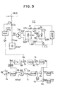
- F ig. 5 is a blcck diagram illustrating another embodiment of a cycloconverter system according to the present invention.
- the cycloconverter system in this embodiment includes a power supply line BUS of a three phase power supply, a power factor compensating capacitor assembly CAP comprising delta or star connected capacitors, a power transformer TR, a cycloconverter CC of the circulating current type, and a load LOAD.
- the cycloconverter CC comprises a positive group converter SSP, a negative group converter SSN, and dc reactors L 01 and L 02 with intermediate taps.
- a control circuit for the cycloconverter cc comprises a load current detector CT L , an output current detector CTp of the positive group converter, an output current detector CT N of the negative group converter, a transformer PT S for detecting a three phase ac voltage at a receiving-end, a current transformer CT S for detecting a three phase ac current, a reactive power computing circuit VAR, comparators C 1 , C 2 , C 3 and C 4 , adders A and A 2 , a multiplier ML, control compensating circuits G N (S), H Q (S), G O (S) and G L (S), an absolute value circuit ABS, a reactive power command value circuit FQ, an operational amplifier K 1 , and phase control circuits PHP and PHN.
- the output I m of the control compensating circuit G N (S) produced when a difference ⁇ 4 between the speed reference N * and the actual rotational speed N is input to the control compensating circuit G N (S) corresponds to an amplitude of the motor current.
- the output I m is fed to the amplifier ML and is then multiplied by a sinewave signal sin ⁇ t synchronous with a speed electromotive force of the motor thereat.
- the load current command I L * is created as an output of the multiplier ML.
- the error ⁇ 3 is input to the load current control compensating circuit G L (S) to carry out proportional amplification or integral amplification.
- a signal V ⁇ N -K L ⁇ 3 obtained by parsing an output signal K L ⁇ 3 from the control compensating circuit G L (S) through the inverting operational amplifier K 1 is input. Accordingly, an output voltage of the negative group converter SSN is expressed as where K V denotes a conversion constant, V S a power supply voltage, and ⁇ P and a N firing phase angles.
- the error ⁇ 3 varies according to this. Accordingly, the above-mentioned firing phase angles ap and a N are controlled in a manner that a sinewave current I L flows in the load. In such an ordinary operation, the voltages of the positive group converter SSP and the negative group converter V N are balanced with each other, with the result that little circulating current I O flows.
- the circulating current I of the cycloconverter is detected as follows.
- the circulating current I O is determined by obtaining the sum of a value detected of the output current I P of the positive group converter SSP to a value detected of the output current I L of the negative converter SSN, subtracting an absolute value of a value detected of the load current I L from the sum, and multiplying it by one-half.
- the relationship is expressed as follows:
- the circulating current I O thus obtained is compared with the command value I O *.
- the error ⁇ 2 undergoes proportional amplification or integral amplification.
- the reactive power control is carried out as follows.
- the three phase current detector CT S and the three phase voltage detector PT S are provided.
- the reactive power Q S is cimputed by the reactive power computation circuit VAR.
- the command value Q * of the reactive power is ordinarily set at zero.
- the reactive power control compensating circuit H Q (S) ordinarily employs integral element in order to allow the steady-state error E1 to be zero.
- the output of the reactive power compensating control circuit H Q (S) becomes the above-mentioned circulating current command value I O *.
- Fig. 6 is a view showing the relationship between voltage and current vectors at the receiving-end wherein the vector relationship represents a single phase of the three phase power supply.
- Icap represents a leading current flowing in the power factor compensating capacitor
- I CC an input current of the cycloconverter
- IS an effective value of the input . value
- I REACT a reactive value of the IREACT.
- I SS p and I SSN represent input currents of the positive and negatige group converters, respective- l y. Where a current conversion factor of the converter is denoted by K 1 , the above-mentioned input currents I SS p and I SSN are expressed as follows:
- This vector view indicates the condition where the load current I L is delivered from the positive group converter SSP.
- the input current I CC of the cycloconverter is obtained as the vector sum of the input currents I CC and I SSP .
- the effective value IS and the reactive value I REACT of the input current I CC can be expressed as follows: where the relationship of ⁇ N ⁇ 180- ⁇ P is introduced in the above derivation. Namely, the circulating current I O flowing in the cycloconverter does not affect the effective value I L on the input side, but affects the reactive value I REACT .
- the current I S delivered from the power supply always becomes effective component, thus maintaining the fundamental wave power factor at unity.
- the load LOAD in Fig. 1 corresponds to an armature winding of the dc motor.
- the load LOAD in Fig. 1 corresponds to one phase of an armature winding of the ac motor.
- an explanation will be made in connection with the ac motor (synchronous motor).
- a rotational speed N of the motor is detected by a tachogenerator or a rotatable pulse generator etc.
- the error ⁇ 4 is input to the speed control compensating circuit G N (S) to carry out proportional amplification or integral amplification.
- the amplitude command value I m of the load current I L to be supplied to the motor winding is determined.
- the multiplier ML is operative to multiply the amplitude command value I m by a unit sinewave (one phase) sinwt synchronous with a rotational position of the motor.
- the cycloconverter operates under condition of a load current below the rated value, it effects a control such that the reactive power at the receiving end becomes zero.
- the cycloconverter operates under an overload condition, it effects a control such that the command value Q 3 * for the reactive power control at the receiving-end is changed depending upon the ma g ni- tude (amplitude I ) of the load current.
- Fig. 6 is circuit diagram illustrating an example of the reactive power command value circuit FQ wherein OA 1 and OA 2 represent inverting operational amplifiers, R 1 to R 5 resistors, D a diode, and VR a level setter.
- an rated value I mo of the load current is set. Assuming that the resistance values of the resistors R 1 to R 3 provided in the inverting operational amplifier OA 1 are equal to each other, (I mo -
- -I mo , the reactive power command value Q 3 * is expressed as Q S * K Q (
- Fig. 7 shows the above-mentioned relationship wherein the load current amplitude
- a proportional constant K Q is determined as a substantially constant such that the circulating current I O of the cycloconverter is not interrupted.
- the circulating current I O of the cycloconverter decreases in inverse proportion to the absolute value I m of the amplitude of the load current I L so that the reactive power Q S becomes zero until the absolute value I m becomes equal to the rated value.
- the reactive power Q s at the receiving-end does not become zero, thus shifting to a control such that the circulating current I is not interrupted in accordance with the lagging reactive power.
- Such a control provides an good effect with respect to harmonics of an input current of the cycloconverter. Namely, where an ac load is employed, there appear harmonics relevant to a frequency on the side of the load in the input current of the cycloconverter. It is considered that occurrence of such harmonics is due to changes in an effective power at the receiving-end of the cycloconverter and changes a reactive power at the receiving-end of the cycloconverter. In the case of a three-phase balanced load, the effective power becomes constant, with the result that harmonics of an input current caused thereby do not occur. However, the reactive power at the receiving-end of the cycloconverter changes every moment according to a phase control. Accordingly, even in the three-phase balanced load, there is a possibility that harmonics occur in a current on the input side.
- the present invention is also applicable to a cycloconverter delta-connected. Furthermore, when a polyphase output cycloconverter is employed, distribution of circulating currents in respective phases is possible. In addition, it is needless to say that various applications can be possible within a range where the gist of the present invention is not changed.
- the present invention can maintain the advantageous features of a cycloconverter of the circulating current type (small distortion in an output current, and high upper limit of an output frequency) even in an overload operation, thus ensuring a stabilized operation. Further, the present invention makes it possible to always maintain a power factor at the receiving-end at unity until the output reaches the rated load operation and to have no necessity of remarkably increasing the capacity of a power factor compensating capacitor connected at the receiving-end of the cycloconverter. Accordingly, an increase in the capacity of a power transformer or a converter required for an overload operation is relatively small, thus an overload operation is relatively small, thus enabling an operation with a high efficiency.
Landscapes
- Engineering & Computer Science (AREA)
- Power Engineering (AREA)
- Ac-Ac Conversion (AREA)
Applications Claiming Priority (4)
| Application Number | Priority Date | Filing Date | Title |
|---|---|---|---|
| JP59273678A JPS61154480A (ja) | 1984-12-27 | 1984-12-27 | サイクロコンバ−タの制御方法 |
| JP273678/84 | 1984-12-27 | ||
| JP124281/85 | 1985-06-10 | ||
| JP60124281A JPS61285072A (ja) | 1985-06-10 | 1985-06-10 | サイクロコンバ−タ装置 |
Publications (3)
| Publication Number | Publication Date |
|---|---|
| EP0186513A2 true EP0186513A2 (fr) | 1986-07-02 |
| EP0186513A3 EP0186513A3 (en) | 1987-11-19 |
| EP0186513B1 EP0186513B1 (fr) | 1992-08-19 |
Family
ID=26460984
Family Applications (1)
| Application Number | Title | Priority Date | Filing Date |
|---|---|---|---|
| EP85309478A Expired - Lifetime EP0186513B1 (fr) | 1984-12-27 | 1985-12-24 | Procédé pour commander un cycloconvertisseur et dispositif approprié |
Country Status (5)
| Country | Link |
|---|---|
| US (1) | US4670826A (fr) |
| EP (1) | EP0186513B1 (fr) |
| KR (1) | KR890004591B1 (fr) |
| CA (1) | CA1257326A (fr) |
| DE (1) | DE3586534T2 (fr) |
Families Citing this family (6)
| Publication number | Priority date | Publication date | Assignee | Title |
|---|---|---|---|---|
| US5214366A (en) * | 1989-11-13 | 1993-05-25 | Siemens Aktiengesellschaft | Three-phase converter for polyphase induction motors |
| JP3723983B2 (ja) * | 1995-09-08 | 2005-12-07 | 株式会社安川電機 | 直列多重3相pwmサイクロコンバータ |
| US7642666B2 (en) * | 2006-11-02 | 2010-01-05 | Hitachi, Ltd. | Wind power generation apparatus, wind power generation system and power system control apparatus |
| US20110006720A1 (en) * | 2009-07-08 | 2011-01-13 | Innosave Ltd. | Method and apparatus for ac motor control |
| US8207699B2 (en) | 2009-07-08 | 2012-06-26 | Innosave Ltd. | Method and apparatus for AC motor control |
| EP2499736B1 (fr) * | 2009-11-10 | 2014-01-08 | ABB Research Ltd. | Appareil et procede de production d'un couple électromagnétique dans une machine électrique |
Family Cites Families (8)
| Publication number | Priority date | Publication date | Assignee | Title |
|---|---|---|---|---|
| US3609509A (en) * | 1970-03-11 | 1971-09-28 | Gen Electric | Feedback control for cycloconverter |
| CH540602A (de) * | 1971-03-13 | 1973-08-15 | Siemens Ag | Steuerschaltungsanordnung für einen Umrichter mit Gleichstromzwischenkreis zur Speisung eines Synchronmotors |
| US3959719A (en) * | 1975-04-30 | 1976-05-25 | General Electric Corporation | Static controller for power factor correction and adaptive filtering |
| US3959720A (en) * | 1975-04-30 | 1976-05-25 | General Electric Corporation | Voltage control system for high frequency link cycloconverter |
| US4418380A (en) * | 1981-09-24 | 1983-11-29 | Tokyo Shibaura Denki Kabushiki Kaisha | Method and apparatus for controlling the circulating current of a cycloconverter |
| JPS5914988A (ja) * | 1982-07-15 | 1984-01-25 | Shinko Electric Co Ltd | サ−マル用紙 |
| JPS59122372A (ja) * | 1982-12-27 | 1984-07-14 | Toshiba Corp | 電力調整装置 |
| US4570214A (en) * | 1984-03-29 | 1986-02-11 | Tokyo Shibaura Denki Kabushiki Kaisha | Reactive power control cycloconverter |
-
1985
- 1985-12-24 EP EP85309478A patent/EP0186513B1/fr not_active Expired - Lifetime
- 1985-12-24 DE DE8585309478T patent/DE3586534T2/de not_active Expired - Lifetime
- 1985-12-24 CA CA000498568A patent/CA1257326A/fr not_active Expired
- 1985-12-27 KR KR1019850010025A patent/KR890004591B1/ko not_active Expired
- 1985-12-27 US US06/813,985 patent/US4670826A/en not_active Expired - Lifetime
Also Published As
| Publication number | Publication date |
|---|---|
| DE3586534D1 (de) | 1992-09-24 |
| CA1257326A (fr) | 1989-07-11 |
| EP0186513B1 (fr) | 1992-08-19 |
| KR890004591B1 (ko) | 1989-11-16 |
| EP0186513A3 (en) | 1987-11-19 |
| US4670826A (en) | 1987-06-02 |
| DE3586534T2 (de) | 1993-01-07 |
| KR860005473A (ko) | 1986-07-23 |
Similar Documents
| Publication | Publication Date | Title |
|---|---|---|
| US5091839A (en) | Method and apparatus for supplying voltage to a three-phase voltage system having a load-carrying neutral conductor with a pulse width modulated three phase invertor | |
| US4984147A (en) | Control method for PWM converter | |
| US5184057A (en) | Control method and device for ac motor | |
| EP0253294B1 (fr) | Système de machine à induction | |
| EP0519635B1 (fr) | Méthode et dispositif pour le contrÔle de la tension de sortie d'un système électrique à courant alternatif | |
| US20020008982A1 (en) | Method and control system for voltage control at a converter station | |
| US4419591A (en) | Multiterminal DC power transmission system | |
| US6201715B1 (en) | Synchronous frame regulation to extract a positive sequence component of a line voltage | |
| US4673823A (en) | Apparatus for operating cycloconverters in parallel fashion | |
| EP0186513A2 (fr) | Procédé pour commander un cycloconvertisseur et dispositif approprié | |
| US4349867A (en) | Control apparatus for a cycloconverter | |
| JPH0783599B2 (ja) | 循環電流形サイクロコンバ−タの制御方法 | |
| JP2000308264A (ja) | 電力変換システム | |
| CA1078921A (fr) | Systeme de commande d'inverseur | |
| KR0186048B1 (ko) | 3상인버터의 출력전압 제어장치 | |
| JP2695009B2 (ja) | 系統連系用電力変換装置の制御装置 | |
| JPH11164568A (ja) | 電力変換装置 | |
| CA1140988A (fr) | Controle de l'angle de coupage d'un inverseur | |
| JPH0221220B2 (fr) | ||
| JPH10191640A (ja) | コンバータの制御装置 | |
| JPH0720370B2 (ja) | 電力変換器の制御回路 | |
| JPS6217950B2 (fr) | ||
| JPH0646566A (ja) | 電力変換器の制御装置 | |
| JPH0470870B2 (fr) | ||
| JPH05932B2 (fr) |
Legal Events
| Date | Code | Title | Description |
|---|---|---|---|
| PUAI | Public reference made under article 153(3) epc to a published international application that has entered the european phase |
Free format text: ORIGINAL CODE: 0009012 |
|
| 17P | Request for examination filed |
Effective date: 19860104 |
|
| AK | Designated contracting states |
Kind code of ref document: A2 Designated state(s): CH DE GB LI |
|
| PUAL | Search report despatched |
Free format text: ORIGINAL CODE: 0009013 |
|
| AK | Designated contracting states |
Kind code of ref document: A3 Designated state(s): CH DE GB LI |
|
| 17Q | First examination report despatched |
Effective date: 19891218 |
|
| GRAA | (expected) grant |
Free format text: ORIGINAL CODE: 0009210 |
|
| AK | Designated contracting states |
Kind code of ref document: B1 Designated state(s): CH DE GB LI |
|
| REF | Corresponds to: |
Ref document number: 3586534 Country of ref document: DE Date of ref document: 19920924 |
|
| PLBE | No opposition filed within time limit |
Free format text: ORIGINAL CODE: 0009261 |
|
| STAA | Information on the status of an ep patent application or granted ep patent |
Free format text: STATUS: NO OPPOSITION FILED WITHIN TIME LIMIT |
|
| 26N | No opposition filed | ||
| PGFP | Annual fee paid to national office [announced via postgrant information from national office to epo] |
Ref country code: CH Payment date: 19931223 Year of fee payment: 9 |
|
| PGFP | Annual fee paid to national office [announced via postgrant information from national office to epo] |
Ref country code: GB Payment date: 19941215 Year of fee payment: 10 |
|
| PG25 | Lapsed in a contracting state [announced via postgrant information from national office to epo] |
Ref country code: LI Effective date: 19941231 Ref country code: CH Effective date: 19941231 |
|
| REG | Reference to a national code |
Ref country code: CH Ref legal event code: PL |
|
| PG25 | Lapsed in a contracting state [announced via postgrant information from national office to epo] |
Ref country code: GB Effective date: 19951224 |
|
| GBPC | Gb: european patent ceased through non-payment of renewal fee |
Effective date: 19951224 |
|
| PGFP | Annual fee paid to national office [announced via postgrant information from national office to epo] |
Ref country code: DE Payment date: 20041216 Year of fee payment: 20 |