EP0186544B1 - Vorrichtung zur Selbstentkalkung - Google Patents
Vorrichtung zur Selbstentkalkung Download PDFInfo
- Publication number
- EP0186544B1 EP0186544B1 EP19850402267 EP85402267A EP0186544B1 EP 0186544 B1 EP0186544 B1 EP 0186544B1 EP 19850402267 EP19850402267 EP 19850402267 EP 85402267 A EP85402267 A EP 85402267A EP 0186544 B1 EP0186544 B1 EP 0186544B1
- Authority
- EP
- European Patent Office
- Prior art keywords
- chamber
- water
- zone
- installation
- receiver
- Prior art date
- Legal status (The legal status is an assumption and is not a legal conclusion. Google has not performed a legal analysis and makes no representation as to the accuracy of the status listed.)
- Expired
Links
Images
Classifications
-
- F—MECHANICAL ENGINEERING; LIGHTING; HEATING; WEAPONS; BLASTING
- F28—HEAT EXCHANGE IN GENERAL
- F28G—CLEANING OF INTERNAL OR EXTERNAL SURFACES OF HEAT-EXCHANGE OR HEAT-TRANSFER CONDUITS, e.g. WATER TUBES OR BOILERS
- F28G5/00—Cleaning by distortion
Definitions
- the subject of the present invention is an installation for producing hot water or steam, such as a fogging apparatus for bakery ovens, a water heater, a percolator, or any other domestic or industrial installation using steam or hot water.
- a self-descaling process is known from FR-A-1 112473. It is also possible to largely avoid scaling of the installation by providing, upstream of the latter, a water softener , but in this case, on the one hand, we must face the costs represented by the periodic replacement of the ion exchange resin and, on the other hand, we supply the installation for producing hot water or steam with water whose pH has been changed.
- the object of the present invention is to remedy these drawbacks by proposing a self-descaling installation which requires no user intervention, no energy input, no chemical product and which is simple and economical.
- the present invention applies to installations of the type comprising a source of cold water, means for controlling the flow of cold water from said source to a receiver, a receiver heated by suitable means and means for producing hot water or steam supplied with water via said receiver, said receiver further comprising means for evacuation to the sewer, the part of the installation upstream of all heating means being called “ cold zone "(Zf) and the part of the installation downstream of said receiver being called” hot zone "(Zc).
- the object of the invention is achieved in that it offers an installation characterized in that it comprises in the hot zone, a chamber opening on the one hand into said production zone and, on the other hand , in the sewer and in that the supply line has, in the cold zone, immediately downstream of the control means, a bypass opening into the sewer.
- the evacuation (s) in the sewer are advantageously open permanently, the flow rate of the evacuation not being significant with respect to the flow rate towards the production area.
- the evacuation to the sewer of the chamber is done by a tube whose evacuation opening is raised relative to the bottom of the chamber.
- the chamber contains, opposite its water inlet, a jet breaker capable of storing calories when the chamber is empty and of returning them to the water when the latter is readmitted into said bedroom.
- a jet breaker capable of storing calories when the chamber is empty and of returning them to the water when the latter is readmitted into said bedroom.
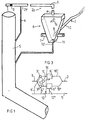
- the installation includes a cold zone Zf and a hot zone Zc.
- the term “cold zone” is intended to mean a zone in which the temperature is between ambient temperature and about 35 ° C.
- a valve 3 controlling the flow of water in the pipe 1 and a bypass 4 joining line 1 to a line 5 for evacuation to the sewer.
- a chamber 6 is interposed, in the hot zone, between the pipe 1 and the steam production zone 2.
- This chamber 6 is mounted against the wall of the furnace (not shown) by appropriate fixing means 7.
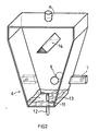
- the chamber 6 comprises a water inlet pipe 8, a water outlet pipe 9 extending by a pipe 10, the end of which forms a water spray nozzle, and a pipe 11 joined to a bypass 12 opening into the pipe d 'evacuation to the sewer 5.
- the pipe 11 projects inside the chamber 6, which has the effect of maintaining a tank bottom 13 as best seen in FIG. 2.
- a jet breaker 14 is provided directly above the water inlet pipe 8 in the chamber 6.
- the diameter of the branches 4 and 12 is much smaller than that of the pipe 9, so that the leaks towards the sewer are not significant compared to the flow of water injected into the zone of steam production 2
- valve 3 When it is desired to produce steam, the valve 3 is opened so that the water is conveyed through line 1 into the chamber 6 from which it emerges through line 10 to be sprayed by the nozzle in the production zone steam 2. A minor amount of water escapes towards the sewer by diversions 4 and 12.
- the valve 3 When it is desired to interrupt the production of steam, the valve 3 is closed, so that a large part of the water contained in the pipe 1, in the area between the valve 3 and the bypass 4, escapes by this bypass to the evacuation pipe to the sewer 5, while the rest of the water contained in the pipe 1 downstream of the valve 3 and the water contained in the chamber 6 flows by the bypass 12 towards the evacuation pipe to the sewer 5.
- the bypass 4 When the bypass 4 is empty, air enters the circuit from the pipe 5, which has the effect of facilitating the emptying of the chamber 6 and cooling the valve 3.
- the chamber 6 empties quickly and the liquid film remaining on its walls evaporates instantly.
- the mineral salts contained in this liquid film are deposited on the walls of the chamber 6 in the form of a thin film of unstructured tartar.
- the particles of tartar resting on the bottom are swept away by the turbulence created during the re-admission of water and evacuated like those which come from the deposit of tartar on the other walls of the tank.
- the hot water does not remain in any part of the installation, a stay which promotes the formation of structured tartar strongly adhering to the walls.
- the hot water is periodically and rapidly removed, which only allows the formation of an unstructured tartar film easily removable by thermal shock and turbulence.
- the invention is applicable both to an installation for the discontinuous production of hot water or steam and to an installation for continuous production, as shown in FIG. 3, where the same components are designated by the same references as 'in Figure 1 but accompanied by the prime or second signs.
- Reference 15 designates a timer actuation mechanism alternately actuating the valves 3 'and 3 ". It is understood that, when the mechanism 15 opens the valve 3', the water enters the chamber 6 'and flows through the line 10 'to the steam production zone 2. When the mechanism 15 closes the valve 3' and opens the valve 3 ", the water enters the chamber 6" and flows through the line 10 "to the steam production 2. In this way, steam is produced continuously in zone 2 while the periodic and alternative interruption of the flow of water in the 6 'and 6 "chambers and the periodic and alternative restoration of this flow in said chambers give the self-scaling effect described in detail with reference to FIGS. 1 and 2.
- the communication between the pipe 1 and the pipe 5, by branch 4, may not be open permanently, but only when valve 3 is closed.
- the bypass 12 permanently open could be doubled with a discharge pipe of larger diameter and which can be opened when the valve 3 is closed to increase the speed of evacuation from the tank 6.
Landscapes
- Engineering & Computer Science (AREA)
- Chemical & Material Sciences (AREA)
- Combustion & Propulsion (AREA)
- Mechanical Engineering (AREA)
- General Engineering & Computer Science (AREA)
- Heat Treatment Of Water, Waste Water Or Sewage (AREA)
- Commercial Cooking Devices (AREA)
Claims (4)
Applications Claiming Priority (2)
| Application Number | Priority Date | Filing Date | Title |
|---|---|---|---|
| FR8417747 | 1984-11-21 | ||
| FR8417747A FR2573522B1 (fr) | 1984-11-21 | 1984-11-21 | Procede et installation d'auto-detartrage. |
Publications (2)
| Publication Number | Publication Date |
|---|---|
| EP0186544A1 EP0186544A1 (de) | 1986-07-02 |
| EP0186544B1 true EP0186544B1 (de) | 1988-11-02 |
Family
ID=9309812
Family Applications (1)
| Application Number | Title | Priority Date | Filing Date |
|---|---|---|---|
| EP19850402267 Expired EP0186544B1 (de) | 1984-11-21 | 1985-11-21 | Vorrichtung zur Selbstentkalkung |
Country Status (3)
| Country | Link |
|---|---|
| EP (1) | EP0186544B1 (de) |
| DE (1) | DE3566037D1 (de) |
| FR (1) | FR2573522B1 (de) |
Families Citing this family (2)
| Publication number | Priority date | Publication date | Assignee | Title |
|---|---|---|---|---|
| CN111076426B (zh) * | 2018-10-22 | 2024-04-02 | 芜湖美的厨卫电器制造有限公司 | 用于热水器的阻垢装置 |
| CN112762758B (zh) * | 2021-01-13 | 2022-04-05 | 绍兴市上虞联丰压力容器有限公司 | 一种换热器的自动清理系统及控制方法 |
Family Cites Families (5)
| Publication number | Priority date | Publication date | Assignee | Title |
|---|---|---|---|---|
| FR523075A (fr) * | 1920-08-26 | 1921-08-11 | Handel Mij H Albert De Bary Mi | Procédé et appareil pour nettoyer les tubes de condenseurs tubulaires, de réchauffeurs d'alimentation, etc. |
| US1884555A (en) * | 1930-07-15 | 1932-10-25 | Griscom Russell Co | Scale shedding heat transfer apparatus |
| FR775664A (fr) * | 1933-07-21 | 1935-01-07 | Sulzer Ag | Générateur tubulaire de vapeur |
| FR1112473A (fr) * | 1953-10-27 | 1956-03-14 | Sulzer Ag | élimination des sels du fluide des générateurs de vapeur |
| GB1103488A (en) * | 1964-07-03 | 1968-02-14 | Marcel Cyprien Kuczweski De Po | Improvements in and relating to heat exchangers |
-
1984
- 1984-11-21 FR FR8417747A patent/FR2573522B1/fr not_active Expired
-
1985
- 1985-11-21 EP EP19850402267 patent/EP0186544B1/de not_active Expired
- 1985-11-21 DE DE8585402267T patent/DE3566037D1/de not_active Expired
Also Published As
| Publication number | Publication date |
|---|---|
| FR2573522B1 (fr) | 1987-05-07 |
| DE3566037D1 (en) | 1988-12-08 |
| FR2573522A1 (fr) | 1986-05-23 |
| EP0186544A1 (de) | 1986-07-02 |
Similar Documents
| Publication | Publication Date | Title |
|---|---|---|
| CA2133701C (fr) | Four muni d'un dispositif de traitement de l'exces de vapeur | |
| EP0323939B1 (de) | Dampferzeuger für Kochgeräte | |
| EP0766526B1 (de) | Vorrichtung zur bereitung von heisswasser oder dampf | |
| EP0785303B1 (de) | Elektrisches Dampfhaushaltgerät mit einer Antikesselsteinvorrichtung | |
| FR2472393A1 (fr) | Atomiseur et dispositif de chauffage associe | |
| FR2519130A1 (fr) | Nettoyage de surfaces tres chaudes du type a jet de liquide pulse | |
| FR2750027A1 (fr) | Dispositif de condensation de vapeurs de cuisson et appareil de cuisson comportant un tel dispositif | |
| FR2821658A1 (fr) | Generateur de vapeur, notamment pour un appareil de cuisson | |
| EP0574341A1 (de) | Bügeleisen mit einer magnetischen Anti-Kesselsteinvorrichtung | |
| FR2593587A1 (fr) | Procede pour la cuisson des aliments en presence de vapeur d'eau et appareil de cuisson s'y rapportant | |
| JP7248350B2 (ja) | 冷凍食品加熱装置 | |
| FR2921551A1 (fr) | Etalage d'exposition de produits alimentaires, notamment pour surface de vente | |
| EP0186544A1 (de) | Vorrichtung zur Selbstentkalkung | |
| FR2619613A1 (fr) | Dispositif d'unite de cuisson par introduction modulable de vapeur fluante avec chemin preferentiel a surchauffeurs et couloir de condensation des vapeurs residuelles | |
| FR2766558A1 (fr) | Dispositif de production d'eau chaude | |
| FR2785975A1 (fr) | Generateur de vapeur a purge rapide | |
| FR2588739A1 (fr) | Appareil electrique pour preparer des boissons chaudes | |
| FR2583141A1 (fr) | Generateur de vapeur a resistance electrique pour appareil electromenager | |
| LU101076B1 (fr) | Système de lavage pour blanchisserie industrielle | |
| BE1032295B1 (fr) | Système de lavage pour blanchisserie industrielle | |
| CH461242A (fr) | Procédé de concentration d'un liquide, notamment de lait, et installation pour sa mise en oeuvre | |
| EP0491605A1 (de) | Elektrischer Wasserkocher mit verbesserter Heizungsanlage | |
| FR2615599A2 (fr) | Perfectionnement a un procede et a un appareil de chauffage a la vapeur | |
| FR2584617A1 (fr) | Dispositif de regeneration de solvant de nettoyage a sec | |
| BE411930A (de) |
Legal Events
| Date | Code | Title | Description |
|---|---|---|---|
| PUAI | Public reference made under article 153(3) epc to a published international application that has entered the european phase |
Free format text: ORIGINAL CODE: 0009012 |
|
| AK | Designated contracting states |
Kind code of ref document: A1 Designated state(s): BE DE GB IT NL SE |
|
| 17P | Request for examination filed |
Effective date: 19861219 |
|
| 17Q | First examination report despatched |
Effective date: 19870605 |
|
| GRAA | (expected) grant |
Free format text: ORIGINAL CODE: 0009210 |
|
| AK | Designated contracting states |
Kind code of ref document: B1 Designated state(s): BE DE GB IT NL SE |
|
| PG25 | Lapsed in a contracting state [announced via postgrant information from national office to epo] |
Ref country code: IT Free format text: LAPSE BECAUSE OF FAILURE TO SUBMIT A TRANSLATION OF THE DESCRIPTION OR TO PAY THE FEE WITHIN THE PRESCRIBED TIME-LIMIT;WARNING: LAPSES OF ITALIAN PATENTS WITH EFFECTIVE DATE BEFORE 2007 MAY HAVE OCCURRED AT ANY TIME BEFORE 2007. THE CORRECT EFFECTIVE DATE MAY BE DIFFERENT FROM THE ONE RECORDED. Effective date: 19881102 Ref country code: NL Effective date: 19881102 Ref country code: GB Free format text: LAPSE BECAUSE OF NON-PAYMENT OF DUE FEES Effective date: 19881102 Ref country code: SE Effective date: 19881102 |
|
| PG25 | Lapsed in a contracting state [announced via postgrant information from national office to epo] |
Ref country code: BE Effective date: 19881130 |
|
| REF | Corresponds to: |
Ref document number: 3566037 Country of ref document: DE Date of ref document: 19881208 |
|
| NLV1 | Nl: lapsed or annulled due to failure to fulfill the requirements of art. 29p and 29m of the patents act | ||
| GBV | Gb: ep patent (uk) treated as always having been void in accordance with gb section 77(7)/1977 [no translation filed] | ||
| BERE | Be: lapsed |
Owner name: VADE JACKY Effective date: 19881130 |
|
| PG25 | Lapsed in a contracting state [announced via postgrant information from national office to epo] |
Ref country code: DE Effective date: 19890801 |
|
| PLBE | No opposition filed within time limit |
Free format text: ORIGINAL CODE: 0009261 |
|
| STAA | Information on the status of an ep patent application or granted ep patent |
Free format text: STATUS: NO OPPOSITION FILED WITHIN TIME LIMIT |
|
| 26N | No opposition filed |